

Internet Routing Architectures, Second Edition
If you want to verify that your regular expression works as intended, use the following EXEC command:
show ip bgp regexp regular-expression
The router displays all the paths that match the specified regular expression. Refer to Table 6- 4 in Chapter 6 for a list of regular expression characters with special meanings.
NOTE
Route maps (referencing AS_PATH access lists) also could have been used to filter updates in the previous example. The filter list was chosen to give you a different option for filtering.
Peer Groups
A BGP peer group is a group of BGP neighbors that share a common set of update policies. Update policies are usually defined by route maps, distribution lists, prefix lists, and filter lists. Instead of defining the same policies for each individual neighbor, you define a peer group name and assign policies to the peer group.
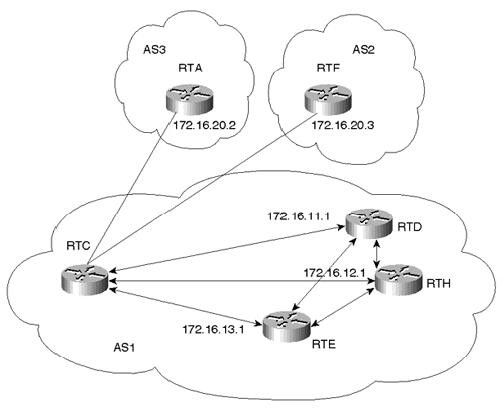
The network shown in Figure 11-3 demonstrates the use of BGP peer groups.
Figure 11-3. BGP Peer Groups
page 280
Internet Routing Architectures, Second Edition
RTC forms similar internal peering sessions with RTD, RTE, and RTH. Instead of formulating and applying similar policies for each neighbor individually, RTC defines a peer group that contains the policies and configures all the internal neighbors as members of the peer group. Example 11-15 illustrates this.
Example 11-15. Configuring a BGP Peer Group
router bgp 1
neighbor INTERNALMAP peer-group neighbor INTERNALMAP remote-as 1
neighbor INTERNALMAP route-map INTERNAL out neighbor INTERNALMAP filter-list 1 out neighbor INTERNALMAP filter-list 2 in neighbor 172.16.11.1 peer-group INTERNALMAP neighbor 172.16.13.1 peer-group INTERNALMAP neighbor 172.16.12.1 peer-group INTERNALMAP neighbor 172.16.12.1 filter-list 3 in
The configuration in Example 11-15 defines a peer group called INTERNALMAP that contains the following policies. (Note that INTERNALMAP is an arbitrary name I've selected; it could be any string. Usually, a descriptive phrase is the most practical.)
•A route map named INTERNAL
•A filter list for outgoing updates (filter list 1)
•A filter list for incoming updates (filter list 2)
The configuration applies the peer group to all internal neighbors—RTD, RTE, and RTH.
Members of a peer group inherit all the configuration options of the peer group. Peer group members can also be configured to override configuration options if the options do not affect outgoing updates. In other words, peer group members can be configured to override options that affect incoming policies. The configuration of RTC, for example, also defines a filter list 3 for incoming updates from the neighbor at IP address 172.16.12.1 (RTH). Filter list 3 will override any incoming policies set by the peer group INTERNALMAP for neighbor RTH.
Example 11-16 demonstrates how to configure a BGP peer group named EXTERNALMAP on RTC and apply it to the exterior neighbors in AS3 and AS2.
Example 11-16. RTC External BGP Peer Group
router bgp 1
neighbor EXTERNALMAP peer-group
neighbor EXTERNALMAP route-map SETMED out neighbor EXTERNALMAP filter-list 1 out neighbor EXTERNALMAP filter-list 2 in neighbor 172.16.20.2 remote-as 3
neighbor 172.16.20.2 peer-group EXTERNALMAP neighbor 172.16.20.3 remote-as 2
neighbor 172.16.20.3 peer-group EXTERNALMAP neighbor 172.16.20.3 filter-list 3 in
ip as-path access-list 1 permit ^$
page 281
Internet Routing Architectures, Second Edition
In the configuration in Example 11-16, the neighbor remote-as router configuration commands are placed outside the neighbor peer-group router configuration commands because different external ASs have to be defined. Also note that this configuration defines filter list 3, which can be used to override configuration options for incoming updates from the neighbor at IP address 172.16.20.3 (RTF).
The following two paragraphs apply only to older IOS versions; these are not restrictions of newer versions.
Note that the external BGP neighbors RTA and RTF that belong in the same peer group EXTERNALMAP were taken from the same subnet, 172.16.20.0. This restriction is needed to prevent loss of information. Placing the external neighbors in different subnets could result in RTC's sending updates to its neighbors (RTA and RTF) with a nonconnected next-hop IP address. These updates would be dropped due to the normal EBGP behavior of ignoring routes with nonconnected next hop (remember that ebgp-multihop was implemented to override this behavior).
Another restriction that applies is that peer groups should not be set on EBGP neighbors if the router is acting as a transit between those neighbors. If the router (RTC) is passing updates from one external neighbor to the other, placing external neighbors in peer groups might result in routes being mistakenly removed. Note that filter list 1 has been defined to allow AS1's local routes only to be sent to neighbors RTA and RTF. This way, RTC will not act as a transit router between RTA and RTF.
Predefined peer groups can ease configuration tasks (while decreasing error probability) when bringing up new peers. They can also significantly decrease the size of BGP configurations in the router. In addition, BGP UPDATE messages are generated only once for members of a peer group and then are copied to all the peers, potentially preserving a considerable amount of CPU resources versus what would be required to generate each UPDATE individually.
Sources of Routing Updates
Routes can be injected dynamically or statically into BGP. The choice of method depends on the number and stability of routes.
Injecting Information Dynamically into BGP
The following example demonstrates how routing information can be injected dynamically into BGP. Consider Figure 11-4.
page 282
Internet Routing Architectures, Second Edition
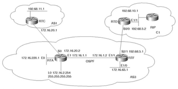
Figure 11-4. Injecting Routes into BGP
Assume that AS3 is getting Internet connectivity from AS1. AS3 is running OSPF as an IGP inside the AS and is running EBGP with AS1.
On the other hand, AS3 also has one customer, C1, with the following criteria:
•C1 is pointing a default toward AS3.
•C1 advertises all its routes to AS3 via RIP.
RTF is running two routing processes—the OSPF process and the RIP process. RTF will only listen to RIP on its connection to C1 and will redistribute the RIP routes it receives from C1 into OSPF. On the other hand, RTA will run two routing processes—the OSPF process and the BGP process. RTA will inject all its local routes, as well as its customer routes, dynamically into BGP. Example 11-17 illustrates this.
The subnets keyword is used to make sure that all subnetted information will be injected into the OSPF process. This is required only when redistributing routes into the OSPF protocol. Example 11-17 illustrates this.
Example 11-17. RTF Redistribution
interface Ethernet1/0
ip address 172.16.65.1 255.255.255.192 interface Ethernet1/1
ip address 172.16.1.2 255.255.255.0 interface Serial2/1
ip address 192.68.5.1 255.255.255.0 router ospf 10
redistribute rip subnets
network 172.16.0.0 0.0.255.255 area 0 router rip
passive-interface Serial2/1 network 192.68.5.0
page 283
Internet Routing Architectures, Second Edition
RTF's configuration introduces two new commands:
•passive-interface type number—
This router command disables sending routing updates on the specified interface. In the example, when used with RIP, this command prevents RIP updates from being sent on interface S2/1. This is in case RTF has multiple customers connected that do not need to see each other's networks.
When used with OSPF, this command disables hello packets from being sent on the specified interface, which therefore prevents link state information from being exchanged on that interface.
•redistribute protocol [process-id]—
The redistribute command injects routes from one routing process into another routing process. In this example, RTF is injecting the RIP routes into the OSPF process (OSPF process 10). Numerous extensions of the redistribute command exist (such as subnets); these extensions will be explained in context.
Note that RTD has configured a static route pointing a 0/0 default toward RTF. For all destinations that are outside C1, RTD will direct the traffic to RTF. RTD will also redistribute the static default route into the internal RIP domain so that all other routers can follow a default toward AS3. The default-metric router command assigns a metric to the routes redistributed into a particular protocol. In this case, the default metric assigns a hop count of 1 to the 0/0 route injected into RIP. Example 11-18 illustrates this.
Example 11-18. RTD Redistributing Static Routes into RIP
interface Ethernet1/1
ip address 192.68.10.1 255.255.255.0 interface Serial0/0
ip address 192.68.5.2 255.255.255.0 router rip
redistribute static network 192.68.5.0 network 192.68.10.0 default-metric 1
ip route 0.0.0.0 0.0.0.0 192.68.5.1
Example 11-19. RTA Redistributing OSPF Routes into BGP
interface Ethernet0
ip address 172.16.220.1 255.255.255.0 interface Ethernet1
ip address 172.16.1.1 255.255.255.0 interface Serial0
ip address 172.16.20.2 255.255.255.0 router ospf 10
passive-interface Serial 0
network 172.16.0.0 0.0.255.255 area 0 router bgp 3
redistribute ospf 10 match external 1 external 2 neighbor 172.16.20.1 remote-as 1
no auto-summary
page 284
Internet Routing Architectures, Second Edition
RTA has a combination of OSPF routes that belong to AS3 and other external routes that came in from the RIP domain C1. Using the redistribute router command, RTA will dynamically inject all these routes into its BGP process. Note that RTA is using the keywords match external 1 external 2 in conjunction with the redistribute router command. This is because OSPF does not inject external OSPF routes into BGP unless it is specifically instructed to do so. This measure was put in for loop avoidance in case the external OSPF information came from BGP.
The output generated in Example 11-20 is a snapshot of what RTA's IP routing table looks like.
Example 11-20. RTA Routing Table
RTA#show ip route
Codes: C - connected, S - static, I - IGRP, R - RIP, M - mobile, B - BGP D - EIGRP, EX - EIGRP external, O - OSPF, IA - OSPF inter area N1 - OSPF NSSA external type 1, N2 - OSPF NSSA external type 2 E1 - OSPF external type 1, E2 - OSPF external type 2, E - EGP
i - IS-IS, L1 - IS-IS level-1, L2 - IS-IS level-2,
* - candidate default U - per-user static route, o - ODR Gateway of last resort is not set
O E2 192.68.5.0/24 [110/20] via 172.16.1.2, 2d13h, Ethernet1 O E2 192.68.10.0/24 [110/20] via 172.16.1.2, 2d13h, Ethernet1
B192.68.11.0/24 [20/0] via 172.16.20.1, 2d13h 172.16.0.0/16 is variably subnetted, 5 subnets, 3 masks
C172.16.2.254/32 is directly connected, Loopback0
C 172.16.220.0/24 is directly connected, Ethernet0 C 172.16.20.0/24 is directly connected, Serial0
C 172.16.1.0/24 is directly connected, Ethernet1
O 172.16.65.0/26 [110/20] via 172.16.1.2, 2d13h, Ethernet1
Note in RTA's IP table how networks 192.68.10.0/24 and 192.68.5.0/24 are listed as external OSPF routes (O E2). Dynamic redistribution will cause all these networks to be sent into BGP. The output generated in Example 11-21 shows how RTC's BGP table would look.
Example 11-21. RTC BGP Routing Table
RTC#show ip bgp
BGP table version is 20, local router ID is 192.68.11.1
Status codes: s suppressed, d damped, h history, * valid, > best,
i - internal Origin |
codes: i - IGP, e - EGP, |
? - incomplete |
|
|
Network |
Next Hop |
Metric |
LocPrf Weight Path |
|
*> 172.16.1.0/24 |
172.16.20.2 |
0 |
0 3 |
? |
*> 172.16.2.254/32 |
172.16.20.2 |
0 |
0 3 |
? |
*> 172.16.20.0/24 |
172.16.20.2 |
0 |
0 3 |
? |
*> 172.16.65.0/26 |
172.16.20.2 |
20 |
0 3 |
? |
*> 172.16.220.0/24 |
172.16.20.2 |
0 |
0 3 |
? |
*> 192.68.5.0 |
172.16.20.2 |
20 |
0 3 |
? |
*> 192.68.10.0 |
172.16.20.2 |
20 |
0 3 |
? |
*> 192.68.11.0 |
0.0.0.0 |
0 |
32768 i |
|
Notice that all networks running OSPF in AS3 have become BGP routes in AS1. Usually, not every network that belongs to your AS needs to be sent via BGP. You might be running private or illegal network numbers inside the AS that should not be advertised externally.
page 285
Internet Routing Architectures, Second Edition
Also notice how the loopback address 172.16.2.254/32 was injected into BGP. Most providers do not accept advertisements of such long prefixes (for example, /32) and will instruct you to filter them—or, more likely, will filter them on their end. This restriction is put in place to make sure that customers are aggregating their routes as much as possible to contain the growth of the global IP routing tables. Also, the DMZ network 172.16.20.0/24 has been injected into BGP, which is not necessary. This is why redistribution should be accompanied by filtering to specify the exact routes that need to be advertised.
The configuration of RTA in Example 11-22 gives an example of how filtering could be applied.
NOTE
From this point forward, due to space limitations, configuration examples will focus on commands that are directly relevant to the discussion at hand. Do not be alarmed if you notice commands that are missing, such as interface commands.
Example 11-22. Filtering Redistributed Routes
router ospf 10 passive-interface Serial0
network 172.16.0.0 0.0.255.255 area 0 router bgp 3
redistribute ospf 10 match external 1 external 2 neighbor 172.16.20.1 remote-as 1
neighbor 172.16.20.1 route-map BLOCKROUTES out no auto-summary
access-list 1 permit 172.16.2.254 0.0.0.0 access-list 1 permit 172.16.20.0 0.0.0.255 route-map BLOCKROUTES deny 10
match ip address 1
route-map BLOCKROUTES permit 20
Filtering in Example 11-22 was performed with a route map, which specifies a set of actions to be taken in case certain criteria are met. The criteria here are to find a match on the host route 172.16.2.254/32 and the network 172.16.20.0/24 and to prevent them from being sent via BGP. The access-list 1 will help you find a match on these routes, and route-map BLOCKROUTES specifies that they should be denied. The second instance of the route map (20) permits all other routes to be injected into BGP. (Refer to the discussion of filtering in Chapter 6 for more details.)
Example 11-23 demonstrates how RTC's BGP table would look after filtering has been applied. The host route 172.16.2.254/32 and the network 172.16.20.0/24 do not show anymore.
page 286
Internet Routing Architectures, Second Edition
Example 11-23. RTC BGP Table After Filtering Is Applied
RTC#show ip bgp
BGP table version is 34, local router ID is 192.68.11.1
Status codes: s suppressed, d damped, h history, * valid, > best, i - internal Origin codes: i - IGP, e - EGP, ? - incomplete
Network |
Next Hop |
Metric LocPrf Weight |
Path |
||
*> 172.16.1.0/24 |
172.16.20.2 |
0 |
0 |
3 |
? |
*> 172.16.65.0/26 |
172.16.20.2 |
20 |
0 |
3 |
? |
*> 172.16.220.0/24 |
172.16.20.2 |
0 |
0 |
3 |
? |
*> 192.68.5.0 |
172.16.20.2 |
20 |
0 |
3 |
? |
*> 192.68.10.0 |
172.16.20.2 |
20 |
0 |
3 |
? |
*> 192.68.11.0 |
0.0.0.0 |
0 |
32768 |
i |
|
To have better control over what is being redistributed from the IGP into BGP, you can use the network command. The network command is a way to individually list the prefixes that need to be sent via BGP. The network command specifies the prefix to be sent out (network and mask). The statement network 172.16.1.0 mask 255.255.255.0, for example, specifies that prefix 172.16.1.0/24 should be sent. Networks that fall on a major net boundary (255.0.0.0, 255.255.0.0, or 255.255.255.0) do not need to have the mask included. For example, the statement network 172.16.0.0 is sufficient to send the prefix 172.16.0.0/16. Such networks are also listed in the BGP routing table without the /x notation. For example, the Class C network 192.68.11.0 is equivalent to 192.68.11.0/24.
Considering Figure 11-4, the configuration of RTA in Example 11-24 will specify the networks that will be injected into BGP.
Example 11-24. RTA Configuration Specifying Networks Injected into BGP
router ospf 10 passive-interface Serial0
network 172.16.0.0 0.0.255.255 area 0 router bgp 3
network 172.16.1.0 mask 255.255.255.0 network 172.16.65.0 mask 255.255.255.192 network 172.16.220.0 mask 255.255.255.0 network 192.68.5.0
network 192.68.10.0
neighbor 172.16.20.1 remote-as 1
no auto-summary
Example 11-25 shows what RTC's BGP table would look like.
Example 11-25. RTC BGP Routing Table
RTC#show ip bgp
BGP table version is 34, local router ID is 192.68.11.1
Status codes: s suppressed, d damped, h history, * valid, > best, i - internal Origin codes: i - IGP, e - EGP, i - incomplete
Network |
Next Hop |
Metric LocPrf Weight |
Path |
||
*> 172.16.1.0/24 |
172.16.20.2 |
0 |
0 |
3 |
i |
*> 172.16.65.0/26 |
172.16.20.2 |
20 |
0 |
3 |
i |
*> 172.16.220.0/24 |
172.16.20.2 |
0 |
0 |
3 |
i |
*> 192.68.5.0 |
172.16.20.2 |
20 |
0 |
3 |
i |
*> 192.68.10.0 |
172.16.20.2 |
20 |
0 |
3 |
i |
*> 192.68.11.0 |
0.0.0.0 |
0 |
32768 |
i |
|
page 287
Internet Routing Architectures, Second Edition
All routes have been injected into BGP except for 172.16.2.254/32 and 172.16.20.0/24. Note that the table looks similar to the one produced when redistributing the OSPF routes into BGP and applying filters. The only noticeable difference is with the origin code, which is indicated by the i at the end of the path information. The i origin code indicates that the source of these networks is internal (IGP) to the originating AS. If you look at the previous snapshot of RTC's BGP table, the origin code was ?, meaning incomplete, which indicates that the origin of these networks is learned by some other means. Anytime routes are injected into BGP via redistribution, the origin code is incomplete, unless otherwise explicitly specified.
The network command takes effect only if the prefixes listed are known to the router. In other words, BGP will not blindly advertise prefixes just because they were listed. The router will check for the availability of an exact match of the prefix in the IP routing table before the network is advertised. In Example 11-25, if you list network 172.16.192.0 mask 255.255.255.0, that network will not be originated, because it is unknown by the router.
Injecting Information Statically into BGP
Listing prefixes with the network command has the same drawbacks as dynamic redistribution. If a route that is listed with the network command goes down, BGP will send an update; if the route comes back, BGP will send another update. If this behavior continues, the IGP instability will translate into BGP instabilities. The only way around this is to use a combination of statically defined prefixes in conjunction with the network command. This will ensure that the prefixes will always remain in the IP routing tables and will always be advertised.
In the previous example, if you wanted to make sure that the fluctuations of route 192.68.10.0/24 did not translate into fluctuations in the BGP, you would have included in RTA a static route of this form:
ip route 192.68.10.0 255.255.255.0 Ethernet1
If you use the static approach, the prefix entry will always be present in the IP routing table and will always be advertised, so long as the Ethernet 1 interface is active. The drawback of this approach is that even when a route is down, it will still be advertised by BGP. Considering the gain in network stability compared to the damage that an ill-behaved route or multiple ill-behaved routes can cause, administrators might find this approach very efficient. The RTA configuration in Example 11-26 ensures that 192.68.10.0/24 is always sent.
Example 11-26. Ensuring That a Route is Always Advertised |
|
router bgp 3 |
|
network 172.16.1.0 mask 255.255.255.0 |
|
network 172.16.65.0 mask 255.255.255.192 |
|
network 172.16.220.0 mask 255.255.255.0 |
|
network 192.68.5.0 |
|
network 192.68.10.0 |
|
neighbor 172.16.20.1 remote-as 1 |
|
no auto-summary |
Ethernet1 |
ip route 192.68.10.0 mask 255.255.255.0 |
page 288