

Internet Routing Architectures, Second Edition
Note that RTA itself is originating the 192.68.10.0/24 prefix and is not relying on the advertisement coming from RTF. In case an aggregate is advertised via a static route, it is better to point the static route to null 0 (bit bucket) for loop prevention.
Overlapping Protocols: Backdoors
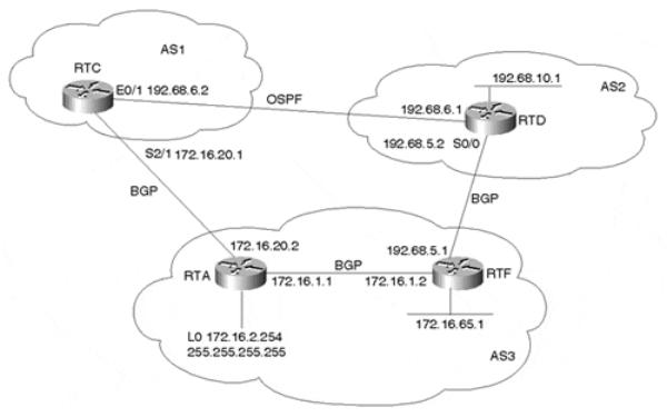
This example shows how the backdoor command can be used to change the EBGP distance to have IGP routes favored over EBGP routes for specific network numbers. Figure 11-5 illustrates the topology for this example.
Figure 11-5. BGP Backdoor Routes
In Figure 11-5, AS2 is running an IGP (OSPF) on the private link between it and AS1, and it is running EBGP with AS3. RTC, in AS1, will receive advertisements about 192.68.10.0/24 from AS3 via EBGP with a distance of 20 and from AS2 via OSPF with a distance of 110. Because the lower distance is preferred, RTC will use the BGP link to AS3 to reach 192.68.10.0/24.
Looking at RTC's IP routing table in Example 11-27 reveals that prefix 192.68.10.0/24 is indeed learned via BGP. RTC will take the longer path via AS3 (next hop 172.16.0.2) to reach 192.68.10.0/24. Note the distance of [20] that the EBGP route has.
Example 11-27. RTC IP Routing Table
RTC#show ip route
Codes: C - connected, S - static, I - IGRP, R - RIP, M - mobile, B - BGP D - EIGRP, EX - EIGRP external, O - OSPF, IA - OSPF inter area E1 - OSPF external type 1, E2 - OSPF external type 2, E - EGP
i - IS-IS, L1 - IS-IS level-1, L2 - IS-IS level-2, * - candidate default U - per-user static route
page 289
Internet Routing Architectures, Second Edition
Gateway of last resort is not set
C 192.68.6.0/24 is directly connected, Ethernet0/1
B192.68.10.0/24 [20/0] via 172.16.20.2, 00:21:36 172.16.0.0/16 is variably subnetted, 3 subnets, 2 masks
C172.16.20.0/24 is directly connected, Serial2/1
B 172.16.1.0/24 [20/0] via 172.16.20.2, 00:21:37
B 172.16.65.0/26 [20/20] via 172.16.20.2, 00:21:37
If you wanted to have RTC prefer the OSPF entry, you would configure RTC as demonstrated in Example 11-28.
Example 11-28. Configuring RTC to Prefer the OSPF Entry
router bgp 1
neighbor 172.16.20.2 remote-as 3 network 192.68.10.0 backdoor
no auto-summary
In Example 11-28, network 192.68.10.0 backdoor changes the distance of the BGP route 192.68.10.0/24 from 20 to 200, which makes the OSPF route with a distance of 110 more preferred. Note that network 192.68.10.0 backdoor will not cause BGP to generate an advertisement for that network.
The output generated in Example 11-29 shows RTC's new routing table. Note that the 192.68.10.0/24 entry is now learned via OSPF with distance [110], and the private link between AS1 and AS2 will be used.
Example 11-29. RTC's New Routing Table
RTC#show ip route
Codes: C - connected, S - static, I - IGRP, R - RIP, M - mobile, B - BGP D - EIGRP, EX - EIGRP external, O - OSPF, IA - OSPF inter area E1 - OSPF external type 1, E2 - OSPF external type 2, E - EGP
i - IS-IS, L1 - IS-IS level-1, L2 - IS-IS level-2, * - candidate default U - per-user static route
Gateway of last resort is not set
C 192.68.6.0/24 is directly connected, Ethernet0/1
O IA 192.68.10.0/24 [110/20] via 192.68.6.1, 00:00:21, Ethernet0/1 172.16.0.0/16 is variably subnetted, 3 subnets, 2 masks
C 172.16.20.0/24 is directly connected, Serial2/1 B 172.16.1.0/24 [20/0] via 172.16.20.2, 00:29:07 B 172.16.65.0/26 [20/20] via 172.16.20.2, 00:29:07
BGP Attributes
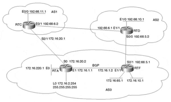
In this section, we will work with the network topology illustrated in Figure 11-6 to demonstrate how the different BGP attributes are used.
page 290
Internet Routing Architectures, Second Edition
Figure 11-6. Applying BGP Attributes
Examples 11-30 through 11-33 are a first run of basic configurations for the routers RTA, RTF, RTC, and RTD illustrated in Figure 11-6. Additional configuration will be added according to the topic under discussion.
Example 11-30. Basic Configuration for RTA in Figure 11-6
ip subnet-zero interface Loopback0
ip address 172.16.2.254 255.255.255.255 interface Ethernet0
ip address 172.16.220.1 255.255.255.0 interface Ethernet1
ip address 172.16.1.1 255.255.255.0 interface Serial0
ip address 172.16.20.2 255.255.255.0 router ospf 10
passive-interface Serial0
network 172.16.0.0 0.0.255.255 area 0 router bgp 3
no synchronization
network 172.16.1.0 mask 255.255.255.0 network 172.16.10.0 mask 255.255.255.0 network 172.16.65.0 mask 255.255.255.192 network 172.16.220.0 mask 255.255.255.0 neighbor 172.16.1.2 remote-as 3
neighbor 172.16.1.2 update-source Loopback0 neighbor 172.16.20.1 remote-as 1
neighbor 172.16.20.1 filter-list 10 out no auto-summary
ip classless
ip as-path access-list 10 permit ^$
page 291
Internet Routing Architectures, Second Edition
Example 11-31. Basic Configuration for RTF in Figure 11-6
ip subnet-zero interface Ethernet0/0
ip address 172.16.10.1 255.255.255.0 interface Ethernet 1/0
ip address 172.16.65.1 255.255.255.192 interface Ethernet1/1
ip address 172.16.1.2 255.255.255.0 interface Serial2/1
ip address 192.68.5.1 255.255.255.0 router ospf 10
network 172.16.0.0 0.0.255.255 area 0 router bgp 3
no synchronization
network 172.16.1.0 mask 255.255.255.0 network 172.16.10.0 mask 255.255.255.0 network 172.16.65.0 mask 255.255.255.192 network 172.16.220.0 mask 255.255.255.0 neighbor 172.16.2.254 remote-as 3 neighbor 172.16.2.254 next-hop-self neighbor 192.68.5.2 remote-as 2 neighbor 192.68.5.2 filter-list 10 out no auto-summary
ip classless
ip as-path access-list 10 permit ^$
Example 11-32. Basic Configuration for RTC in Figure 11-6
ip subnet-zero interface Ethernet0/0
ip address 192.68.11.1 255.255.255.0 interface Ethernet0/1
ip address 192.68.6.2 255.255.255.0 interface Serial2/1
ip address 172.16.20.1 255.255.255.0 router bgp 1
network 192.68.11.0
neighbor 172.16.20.2 remote-as 3 neighbor 192.68.6.1 remote-as 2 no auto-summary
ip classless
Example 11-33. Basic Configuration for RTD in Figure 11-6
ip subnet-zero interface Ethernet1/0
ip address 192.68.10.1 255.255.255.0 interface Ethernet1/1
ip address 192.68.6.1 255.255.255.0 interface Serial0/0
ip address 192.68.5.2 255.255.255.0 router bgp 2
network 192.68.10.0
neighbor 192.68.5.1 remote-as 3 neighbor 192.68.6.2 remote-as 1 no auto-summary
ip classless
page 292
Internet Routing Architectures, Second Edition
AS3 is assumed to be a nontransit AS. This is why filter-list 10 is applied to force AS3 to originate its local routes only. Routes learned from AS1 or AS2 will not be propagated outside the AS. Also note that some networks such as 172.16.10.0/24 are advertised via the network command on both RTA and RTF. This will ensure that a link failure between AS3 and either AS1 or AS2 will not prevent such networks from being advertised.
The NEXT_HOP Attribute
In the next few examples we'll discuss the BGP NEXT_HOP attribute and provide examples of ways to manipulate the NEXT_HOP value.
Example 11-34 shows the BGP table for RTF.
Example 11-34. BGP Table for RTF
RTF#show ip bgp
BGP table version is 8, local router ID is 192.68.5.1
Status codes: s suppressed, d damped, h history, * valid, > best,
|
i - internal Origin codes: i - IGP, e - EGP, ? - incomplete |
|
|
|||||
|
Network |
Next Hop |
Metric LocPrf Weight Path |
|
||||
* i172.16.1.0/24 |
172.16.2.254 |
0 |
100 |
0 |
i |
|
|
|
*> |
|
0.0.0.0 |
0 |
100 |
32768 |
i |
|
|
* i172.16.10.0/24 |
172.16.2.254 |
20 |
0 |
i |
|
|
||
*> |
|
0.0.0.0 |
0 |
100 |
32768 |
i |
|
|
* i172.16.65.0/26 |
172.16.2.254 |
20 |
0 |
i |
|
|
||
*> |
|
0.0.0.0 |
0 |
100 |
32768 |
i |
|
|
* i172.16.220.0/24 |
172.16.2.254 |
0 |
0 |
i |
|
|
||
*> |
|
172.16.1.1 |
20 |
|
32768 |
i |
i |
|
*> 192.68.10.0 |
192.68.5.2 |
0 |
|
0 |
2 |
i |
||
* |
192.68.11.0 |
192.68.5.2 |
0 |
100 |
0 |
2 |
1 |
|
*>i |
172.16.20.1 |
0 |
1 |
i |
|
|||
Network 192.68.11.0/24 is learned via IBGP (note the i at the far right) with NEXT_HOP 172.16.20.1, which is the IP address of RTA's external neighbor. The EBGP NEXT_HOP IP address is usually preserved inside the routing domain, which is why it is very important to have an internal route to the NEXT_HOP. Otherwise, the BGP route would be unusable. There are a couple of ways to make sure that you do not have problems reaching the EBGP NEXT_HOP. The first way is to include the network that the next hop belongs to in the IGP. This is illustrated on RTA by including interface serial 0 in the OSPF; this way, RTF would know about 172.16.20.1. Note that even though OSPF is running on RTA interface serial 0, it need not exchange any OSPF hello packets on serial 0—hence the passive-interface router command.
The second method is to use the next-hop-self neighbor command (see Example 11-31) to force the router to advertise itself, rather than the external peer, as the next hop. In the RTF configuration in Example 11-31, note how the next-hop-self command is added at the end of the neighbor statement toward RTA. This way, when RTF advertises external networks such as 192.68.10.0/24 toward RTA, it will use itself as the NEXT_HOP. Looking at RTA's BGP table in Example 11-35, the prefix 192.68.10.0/24 is learned via NEXT_HOP 172.16.1.2, which is its internal peer with RTF. Because 172.16.1.2 is part of the OSPF path already, you have no problem reaching it.
page 293
Internet Routing Architectures, Second Edition
Example 11-35. RTA BGP Table
RTA#show ip bgp
BGP table version is 20, local router ID is 172.16.2.254
Status codes: s suppressed, d damped, h history, * valid, > best,
i - internal Origin codes: i - IGP, e - EGP, ? - incomplete |
|
|
|||||
Network |
Next Hop |
Metric LocPrf Weight Path |
|
||||
* i172.16.1.0/24 |
172.16.1.2 |
0 |
100 |
0 |
i |
|
|
*> |
0.0.0.0 |
0 |
100 |
32768 |
i |
|
|
* i172.16.10.0/24 |
172.16.1.2 |
0 |
0 |
i |
|
|
|
*> |
172.16.1.2 |
20 |
100 |
32768 |
i |
|
|
* i172.16.65.0/26 |
172.16.1.2 |
0 |
0 |
i |
|
|
|
*> |
172.16.1.2 |
20 |
100 |
32768 |
i |
|
|
* i172.16.220.0/24 |
172.16.1.2 |
20 |
0 |
i |
|
|
|
*> |
0.0.0.0 |
0 |
100 |
32768 |
i |
i |
|
*>i192.68.10.0 |
172.16.1.2 |
0 |
0 |
2 |
i |
||
* |
172.16.20.1 |
0 |
|
0 |
1 |
2 |
|
*> 192.68.11.0 |
172.16.20.1 |
|
0 |
1 |
i |
|
|
Note in Example 11-35 that 192.68.10.0/24 is actually learned via two different paths, whereas 192.68.11.0/24 is learned via a single path. This might seem misleading, but actually routing is doing the right thing. In this situation, RTF has decided that the best path to reach 192.68.11.0/24 is via RTA (check RTF's BGP table in Example 11-34). This is why RTF will not advertise network 192.68.11.0/24 back to RTA and why RTA will have a single entry for 192.68.11.0/24.
The AS_PATH Attribute
Looking at RTF's BGP table in Example 11-36, you can see the AS_PATH information at the end of each line. Network 192.68.11.0/24 is learned via IBGP with AS_PATH 1 and via EBGP with AS_PATH 2 1. This means that if RTF wanted to reach 192.68.11.0/24 via IBGP, it could go to AS1, and if RTF wanted to reach 192.68.11.0/24 via EBGP, it would have to go via AS2 and then AS1. BGP always prefers the shortest path, which is why the path via IBGP with AS_PATH 1 is preferred. The > at the left indicates that out of the two available paths that BGP has for 192.68.11.0/24, BGP prefers the second one as being the "best" path.
Example 11-36. RTF BGP Table
RTF#show ip bgp
BGP table version is 8, local router ID is 192.68.5.1
Status codes: s suppressed, d damped, h history, * valid, > best,
|
i - internal Origin codes: i - IGP, e - EGP, ? - incomplete |
|
|
|||||
|
Network |
Next Hop |
Metric LocPrf Weight Path |
|
||||
* i172.16.1.0/24 |
172.16.2.254 |
0 |
100 |
0 |
i |
|
|
|
*> |
|
0.0.0.0 |
0 |
100 |
32768 |
i |
|
|
* i172.16.10.0/24 |
172.16.2.254 |
20 |
0 |
i |
|
|
||
*> |
|
0.0.0.0 |
0 |
100 |
32768 |
i |
|
|
* i172.16.65.0/26 |
172.16.2.254 |
20 |
0 |
i |
|
|
||
*> |
|
0.0.0.0 |
0 |
100 |
32768 |
i |
|
|
* i172.16.220.0/24 |
172.16.2.254 |
0 |
0 |
i |
|
|
||
*> |
|
172.16.1.1 |
20 |
|
32768 |
i |
i |
|
*> 192.68.10.0 |
192.68.5.2 |
0 |
|
0 |
2 |
i |
||
* |
192.68.11.0 |
192.68.5.2 |
0 |
100 |
0 |
2 |
1 |
|
*>i |
172.16.20.1 |
0 |
1 |
i |
|
|||
page 294
Internet Routing Architectures, Second Edition
AS_PATH Manipulation
Considering RTF's BGP table in Example 11-36, RTF has picked the direct path via AS1 to reach 192.68.11.0/24 because it is shorter. The configuration in Example 11-37 shows how the AS_PATH information can be manipulated to make the AS_PATH longer by prepending AS numbers to the path. Considering the network illustrated earlier in Figure 11-6, Example 11-37 prepends two extra AS numbers to the AS_PATH information sent from RTC to RTA to change RTF's decision about reaching 192.68.11.0/24.
Example 11-37. Manipulating AS_PATH Information by Prepending AS Numbers
router bgp 1 network 192.68.11.0
neighbor 172.16.20.2 remote-as 3
neighbor 172.16.20.2 route-map AddASnumbers out neighbor 192.68.6.1 remote-as 2
no auto-summary
route-map AddASnumbers permit 10 set as-path prepend 1 1
The configuration in Example 11-37 prepends two additional AS_PATH numbers 1 and 1 (1 twice) to the AS_PATH information sent from RTC to RTA. If you look at RTF's BGP table in Example 11-38, you will see that RTF can now reach 192.68.11.0/24 via NEXT_HOP 192.68.5.2—that is, via path 2 1. RTF will prefer this path because it is shorter than the direct path via AS1, which now has three ASs included in the path information (1 1 1).
Example 11-38. RTF BGP Table After AS_PATH Manipulation
RTF#show ip bgp
BGP table version is 18, local router ID is 192.68.5.1
Status codes: s suppressed, d damped, h history, * valid, > best,
i - internal Origin codes: i - IGP, e - EGP, ? - incomplete |
|
|
|||||
Network |
Next Hop |
Metric LocPrf Weight Path |
|
||||
* i172.16.1.0/24 |
172.16.2.254 |
0 |
100 |
0 |
i |
|
|
*> |
0.0.0.0 |
0 |
100 |
32768 |
i |
|
|
* i172.16.10.0/24 |
172.16.2.254 |
20 |
0 |
i |
|
|
|
*> |
0.0.0.0 |
0 |
100 |
32768 |
i |
|
|
* i172.16.65.0/26 |
172.16.2.254 |
20 |
0 |
i |
|
|
|
*> |
0.0.0.0 |
0 |
100 |
32768 |
i |
|
|
* i172.16.220.0/24 |
172.16.2.254 |
0 |
0 |
i |
|
|
|
*> |
172.16.1.1 |
20 |
|
32768 |
i |
i |
|
*> 192.68.10.0 |
192.68.5.2 |
0 |
|
0 |
2 |
i |
|
*> 192.68.11.0 |
192.68.5.2 |
0 |
100 |
0 |
2 |
1 |
|
* i |
172.16.20.1 |
0 |
1 |
1 |
1 i |
||
Using Private ASs
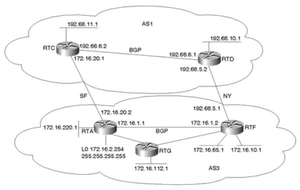
The example in this section demonstrates how BGP can be configured to prevent the leakage of private AS numbers into the Internet. Figure 11-7 illustrates the network topology discussed in this section.
page 295
Internet Routing Architectures, Second Edition
Figure 11-7. Removing Private AS Numbers
Through the configuration of RTA in Example 11-39 and RTC in Example 11-40, AS1 will prevent private AS number 65001 from being leaked to the Internet when BGP routes are propagated.
Example 11-39. RTA Configuration to Prevent Leaking Private AS Numbers
router bgp 65001
network 172.16.220.0 mask 255.255.255.0 neighbor 172.16.20.1 remote-as 1
no auto-summary
Example 11-40. RTC Configuration to Prevent Leaking Private AS Numbers
router bgp 1
network 192.68.11.0 mask 255.255.255.0 neighbor 172.16.20.2 remote-as 65001 neighbor 192.68.6.3 remote-as 7 neighbor 192.68.6.3 remove-private-AS no auto-summary
Note how the RTC configuration in Example 11-40 uses the remove-private-AS keyword in its neighbor connection to AS7. The output in Example 11-41 shows the BGP tables of RTC and RTE.
page 296
Internet Routing Architectures, Second Edition
Example 11-41. BGP Tables for RTC and RTE
RTC#show ip bgp
BGP table version is 72, local router ID is 192.68.11.1
Status codes: s suppressed, d damped, h history, * valid, > best, i - internal Origin codes: i - IGP, e - EGP, ? - incomplete
Network |
Next Hop |
Metric LocPrf Weight |
Path |
|
*> 172.16.220.0/24 |
172.16.20.2 |
0 |
0 |
65001 i |
*> 192.68.11.0 |
0.0.0.0 |
0 |
32768 |
i |
RTE#show ip bgp
BGP table version is 245, local router ID is 192.68.30.1 Status codes: s suppressed, * valid, > best, i - internal Origin codes: i - IGP, e - EGP, ? - incomplete
Network |
Next Hop |
Metric LocPrf Weight |
Path |
||
*> 172.16.220.0/24 |
192.68.6.2 |
0 |
0 |
1 |
i |
*> 192.68.11.0 |
192.68.6.2 |
0 |
1 |
i |
|
Note that prefix 172.16.220.0/24 has an AS_PATH of 65001 in RTC's BGP table and an AS_PATH of 1 in RTE's BGP table. RTC has stripped the private AS path information when propagating the update to AS7. Note that the remove-private-AS command applies to egress routes, and therefore is applied at the egress points of the network.
The LOCAL_PREF Attribute
Setting the local preference (via the LOCAL_PREF attribute) also affects the BGP decision process. If multiple paths for the same prefix are available, the path with the larger local preference value is preferred. LOCAL_PREF is an AS-wide attribute at the highest level of the BGP decision process (it's considered just after the weight parameter, which is Ciscoproprietary and local to the router); it is considered before the AS path length. A longer path with a larger local preference is preferred over a shorter path with a smaller local preference. Example 11-42 (still referring to the network in Figure 11-7) configures RTF to have a higher local preference for all BGP updates coming from RTD.
Example 11-42. Configuring RTF to Have a Higher Local Preference for BGP Updates Originating from RTD
router bgp 3
no synchronization
network 172.16.1.0 mask 255.255.255.0 network 172.16.10.0 mask 255.255.255.0 network 172.16.65.0 mask 255.255.255.192 network 172.16.220.0 mask 255.255.255.0 neighbor 172.16.2.254 remote-as 3 neighbor 172.16.2.254 next-hop-self neighbor 192.68.5.2 remote-as 2 neighbor 192.68.5.2 filter-list 10 out
neighbor 192.68.5.2 route-map SETLOCAL in no auto-summary
ip as-path access-list 10 permit ^$ route-map SETLOCAL permit 10
set local-preference 300
page 297
Internet Routing Architectures, Second Edition
route-map SETLOCAL assigns a local preference of 300 (note that the default local preference value is normally 100) for all routes coming from RTD (note the keyword in). Note in Example 11-43 how BGP has decided that prefixes 192.68.10.0/24 and 192.68.11.0/24 can now be reached via NEXT_HOP 192.68.5.2 having a local preference of 300.
Example 11-43. RTF BGP Table
RTF#show ip bgp
BGP table version is 20, local router ID is 192.68.5.1
Status codes: s suppressed, d damped, h history, * valid, > best, i - internal Origin codes: i - IGP, e - EGP, ? - incomplete
Network |
Next Hop |
Metric LocPrf Weight |
Path |
|||
*> 172.16.1.0/24 |
0.0.0.0 |
0 |
100 |
32768 |
i |
|
* i |
172.16.2.254 |
0 |
0 |
i |
|
|
*> 172.16.10.0/24 |
0.0.0.0 |
0 |
100 |
32768 |
i |
|
* i |
172.16.2.254 |
20 |
0 |
i |
|
|
*> 172.16.65.0/26 |
0.0.0.0 |
0 |
100 |
32768 |
i |
|
* i |
172.16.2.254 |
20 |
0 |
i |
|
|
*> 172.16.220.0/24 |
172.16.1.1 |
20 |
100 |
32768 |
i |
|
* i |
172.16.2.254 |
0 |
0 |
i |
i |
|
*> 192.68.10.0 |
192.68.5.2 |
0 |
300 |
0 |
2 |
|
*> 192.68.11.0 |
192.68.5.2 |
|
300 |
0 |
2 |
1 i |
Because the LOCAL_PREF attribute is carried inside the AS, RTF will pass the local preference value to RTA, as illustrated in Example 11-44, which shows RTA's BGP table.
Example 11-44. RTA BGP Table Reveals the Local Preference Value
RTA#show ip bgp
BGP table version is 43, local router ID is 172.16.2.254
Status codes: s suppressed, d damped, h history, * valid, > best,
i - internal Origin codes: i - IGP, e - EGP, ? - incomplete |
|
|
|||||
Network |
Next Hop |
Metric LocPrf Weight Path |
|
||||
* i172.16.1.0/24 |
172.16.1.2 |
0 |
100 |
0 |
i |
|
|
*> |
0.0.0.0 |
0 |
100 |
32768 |
i |
|
|
* i172.16.10.0/24 |
172.16.1.2 |
0 |
0 |
i |
|
|
|
*> |
172.16.1.2 |
20 |
100 |
32768 |
i |
|
|
* i172.16.65.0/26 |
172.16.1.2 |
0 |
0 |
i |
|
|
|
*> |
172.16.1.2 |
20 |
100 |
32768 |
i |
|
|
* i172.16.220.0/24 |
172.16.1.2 |
20 |
0 |
i |
|
|
|
*> |
0.0.0.0 |
0 |
300 |
32768 |
i |
i |
|
*>i192.68.10.0 |
172.16.1.2 |
0 |
0 |
2 |
i |
||
* |
172.16.20.1 |
|
300 |
0 |
1 |
2 |
|
*>i192.68.11.0 |
172.16.1.2 |
0 |
0 |
2 |
1 |
i |
|
* |
172.16.20.1 |
|
0 |
1 |
i |
|
|
Notice how prefix 192.68.11.0/24 is preferred via IBGP with a local preference of 300, even though the AS_PATH via EBGP is shorter. Other prefixes learned via IBGP, such as 172.16.10.0/24, have a default local preference of 100.
The MULTI_EXIT_DISC Attribute
This section demonstrates how metrics can be used by one AS to influence routing decisions of another AS. In Figure 11-8, AS3 is the customer of provider AS1. AS3 wants to generate
page 298
Internet Routing Architectures, Second Edition
metrics toward AS1 to influence inbound traffic. In case all BGP attributes are the same, BGP will prefer routes with a lower metric over routes with a higher metric.
Figure 11-8. Setting the MED Attribute
RTA and RTF are running IBGP internally and EBGP with the provider AS1. RTG is an internal non-BGP router, running OSPF only. Assume that RTA and RTF want to send MEDs toward AS1 to achieve the following:
•Incoming traffic toward network 172.16.1.0/24 takes the SF link.
•Incoming traffic toward all other networks should come in by using the border router that can reach these networks with a smaller internal metric. Incoming traffic toward network 172.16.112.0/24, for example, should come in on the SF link if RTA can reach this network with a smaller internal metric than RTF.
Example 11-45 and Example 11-46 show the required configuration for RTA and RTF to satisfy these criteria.
Example 11-45. Setting the MED Attribute: RTA Configuration
router ospf 10 passive-interface Serial0
network 172.16.0.0 0.0.255.255 area 0 router bgp 3
no synchronization
network 172.16.1.0 mask 255.255.255.0 network 172.16.10.0 mask 255.255.255.0 network 172.16.65.0 mask 255.255.255.192 network 172.16.220.0 mask 255.255.255.0 network 172.16.112.0 mask 255.255.255.0 neighbor 172.16.1.2 remote-as 3
page 299
Internet Routing Architectures, Second Edition
neighbor 172.16.1.2 update-source Loopback0 neighbor 172.16.20.1 remote-as 1
neighbor 172.16.20.1 filter-list 10 out no auto-summary
ip as-path access-list 10 permit ^$
Example 11-46. Setting the MED Attribute: RTF Configuration
router ospf 10
network 172.16.0.0 0.0.255.255 area 0 router bgp 3
no synchronization
network 172.16.1.0 mask 255.255.255.0 network 172.16.10.0 mask 255.255.255.0 network 172.16.65.0 mask 255.255.255.192 network 172.16.220.0 mask 255.255.255.0 network 172.16.112.0 mask 255.255.255.0 neighbor 172.16.2.254 remote-as 3 neighbor 172.16.2.254 next-hop-self neighbor 192.68.5.2 remote-as 1
neighbor 192.68.5.2 route-map SETMETRIC out neighbor 192.68.5.2 filter-list 10 out
no auto-summary
ip as-path access-list 10 permit ^$ access-list 1 permit 172.16.1.0 0.0.0.255 route-map SETMETRIC permit 10
match ip address 1 set metric 50
route-map SETMETRIC permit 20
The configurations in Example 11-45 and 11-46 will make RTF generate prefix 172.16.1.0/24 with a MED of 50. When AS1 gets the prefix, AS1 will compare a metric of 50 coming from RTF to a metric of 0 coming from RTA and will prefer the SF link. All other networks will be advertised with their internal metrics carried into BGP, and AS1 will choose the entrance that has a smaller metric to the destination. Example 11-47 shows RTD's BGP table after the changes.
Example 11-47. RTD BGP Table
RTD#show ip bgp
BGP table version is 17, local router ID is 192.68.10.1
Status codes: s suppressed, d damped, h history, * valid, > best, i - internal Origin codes: i - IGP, e - EGP, ? - incomplete
* |
Network |
Next Hop |
Metric LocPrf Weight |
Path |
|||
172.16.1.0/24 |
192.68.5.1 |
50 |
100 |
0 |
3 |
i |
|
*>i |
|
192.68.6.2 |
0 |
0 |
3 |
i |
|
*> 172.16.10.0/24 |
192.68.5.1 |
0 |
|
0 |
3 |
i |
|
*> 172.16.65.0/26 |
192.68.5.1 |
0 |
|
0 |
3 |
i |
|
* |
172.16.112.0/24 |
192.68.5.1 |
84 |
100 |
0 |
3 |
i |
*>i |
172.16.220.0/24 |
192.68.6.2 |
74 |
0 |
3 |
i |
|
* |
192.68.5.1 |
20 |
100 |
0 |
3 |
i |
|
*>i |
|
192.68.6.2 |
0 |
0 |
3 |
i |
|
*> 192.68.10.0 |
0.0.0.0 |
0 |
100 |
32768 |
i |
|
|
*>i192.68.11.0 |
192.68.6.2 |
0 |
0 |
i |
|
||
page 300
Internet Routing Architectures, Second Edition
Note from the BGP table in Example 11-47 how RTD prefers network 172.16.1.0/24 via NEXT_HOP 192.68.6.2, which is RTC (RTC is using next-hop-self). This is because of the lower metric (0 is less than 50). For all other networks, RTD prefers routes that have smaller metrics. Note that 172.16.112.0/24 is learned via metric 74 from RTA and via metric 84 from RTF. RTD will prefer the SF link to reach 172.16.112.0/24.
For BGP learned routes, an AS can also advertise these routes to another AS with the internal IGP metric carried into BGP. This is achieved by using the set metric-type internal command as part of a route map toward a neighbor. This would cause BGP routes to carry the internal IGP metric as the BGP MED.
The COMMUNITY Attribute
This section demonstrates how the COMMUNITY attribute can be used to dynamically influence the routing decisions of another AS. With the network illustrated in Figure 11-9, the configuration example in Example 11-48 shows how AS3 can advertise route 172.16.65.0/26 to AS1 and dynamically instructs AS1 not to advertise this route externally. AS3 will assign route 172.16.65.0/26 the COMMUNITY attribute no-export when advertising it to AS1.
Figure 11-9. Setting the COMMUNITY Attribute
Example 11-48. RTA Configuration Using the COMMUNITY Attribute
router bgp 3
no synchronization
network 172.16.1.0 mask 255.255.255.0 network 172.16.10.0 mask 255.255.255.0 network 172.16.65.0 mask 255.255.255.192 network 172.16.220.0 mask 255.255.255.0 neighbor 172.16.1.2 remote-as 3
neighbor 172.16.1.2 update-source Loopback0 neighbor 172.16.20.1 remote-as 1
page 301