


Internet Routing Architectures, Second Edition
Router Collocation
Collocation is the act of placing one party's equipment on another party's premises. An example of collocation is putting the customer's router at the provider's site or hosting center, as illustrated in Figure 2-12. The customer motivations for such a collocation scheme would be to have the ISP provide faster access speeds or local monitoring of the equipment, or perhaps to give the customer better control of access bandwidth utilization.
Figure 2-12. Collocation Example: Customer Router Located at ISP Site
The opposite of the situation described in Figure 2-12 is for the ISP to collocate its own POP router at the customer's site, as illustrated in Figure 2-13. Usually in this case, the ISP would purchase the access line and the router and would charge the customer a fee for the entire service.
Figure 2-13. Collocation Example: ISP Router Located at Customer Site
Looking Ahead
The technical characteristics of an ISP's network have significant repercussions for the customer's service, including the quality of routing architecture. Because the customer might not have direct control over some of these characteristics, it is critical that the customer at least evaluate them and ensure that they will deliver the required connectivity and quality.
If you are an ISP customer whose demarcation point and collocation agreements stipulate that you are running and maintaining equipment on your premises—even if you do not own it outright—you are likely to be taking a significant hands-on role in developing the routing policies and architecture for your network. Even if you are not running and maintaining the equipment, there are decisions you will need to make and understand with respect to routing architecture.
page 50
Internet Routing Architectures, Second Edition
The next chapter completes the foundational part of the book by discussing fundamentals of Internet addressing and address space depletion. After that groundwork has been established, Part II of this book provides an in-depth discussion of routing protocols.
Frequently Asked Questions
Q—
Is higher pricing an indication that I will receive a faster, better connection from an ISP?
A—
Not necessarily. Higher prices sometimes reflect the provider's having invested in fast connections, such as OC12 or OC48 backbone links. The mere presence of such links, however, does not necessarily mean that your connections will be faster. A poorly designed combination of high-speed links and low-speed clouds, for example, might negatively affect the provider's overall performance. The bottom line is that price is just one factor to consider. Even more important is a sound network topology that offers enough redundancy and adequate bandwidth to fit your needs.
Q—
What causes bottlenecks in the ISP's backbone?
A—
Bottlenecks are caused by oversubscription or overutilization of bandwidth on a physical link.
Q—
When I connect to an ISP, should I buy my own equipment?
A—
There are pros and cons to buying your own equipment; only you can decide whether this is the optimal approach for your organization's needs. First, find out whether your ISP insists on your using its equipment (some do). Even if the ISP will let you purchase your own CPE, it probably will stipulate certain hardware and software that conform to its system. Cost issues are likely to factor significantly in your decision. Can your organization afford the capital investment, including upgrades and expansion as needed? By buying the equipment, you might also be committing yourself to maintaining it, although some ISPs will agree to maintain (for a fee) equipment owned by the customer.
In many countries, government regulations impose strict limitations on the equipment used. Understanding the available options is important.
Q—
If my connection to an ISP goes down because of equipment failure, who is responsible for what?
page 51
Internet Routing Architectures, Second Edition
A—
It all depends on the service you are getting from the ISP. The preset demarcation point defines the line of responsibility between you and the provider.
page 52
Internet Routing Architectures, Second Edition
Chapter 3. IP Addressing and Allocation Techniques
This chapter covers the following key topics:
•Overview of Internet addressing— Provides an overview of IPv4 Class A/B/C addressing and basic subnetting concepts.
•Variable-length subnet masks (VLSMs)— Provides a description of variable-length subnet masks and how they can be used in efficient assignment of the IP address space.
•IP address space depletion— Discusses how the problem of IP address space depletion is being managed through creative address allocation, supernetting, private addressing, and next-generation protocols.
•Private addressing and Network Address Translation (NAT)— Discusses how NAT software is used to map between private and global IP addresses.
•IP version 6 (IPv6)— Provides an overview of the IP next generation (IPng) addressing scheme and how it maps to the hierarchical model offered by CIDR and IPv4.
This chapter begins with a brief history of Internet addressing, providing information on traditional IP version 4 (IPv4) addressing and subnetting models. From there, you'll learn about some of the issues surrounding address space depletion on the Internet. Then we'll examine IP addressing techniques and allocation strategies such as variable-length subnet masking (VLSM), classless interdomain routing (CIDR), and Network Address Translation (NAT). The chapter finishes with a brief introduction to IP version 6 (IPv6).
Addressing strategies are of direct and fundamental relevance to routing architecture in any network. One of the basic functions of routing architecture and routers is to accommodate addresses for all the traffic they direct. With the explosive growth of the Internet, the sheer number of addresses and the evolution of new addressing strategies have presented new challenges for routing architectures. An understanding of the history and fundamentals of IP addressing will no doubt play a key role in your ability to quickly grasp routing protocol concepts.
History of Internet Addressing
The addressing scheme that is used today in the Internet is based on version 4 of the Internet Protocol (IPv4)[], usually referred to simply as IP. This section discusses the following:
•Basic IP addressing
•Basic IP subnetting[]
•Variable-length subnet mask (VLSM)[]
Basic IP Addressing
An IP address is a unique 4-octet (32-bit) value expressed in dotted-decimal (or dotted-quad) notation of the form W.X.Y.Z, where periods (dots) are used to separate each of the 4 octets of the address (for example, 10.0.0.1). The 32-bit address field consists of two parts: a
page 53

Internet Routing Architectures, Second Edition
network or link number (which represents the network portion of the address) and a host number (which identifies a host on the network segment).
The network and host boundaries were traditionally defined based on the class of the IP address, with five defined classes (three of which are used for unicast addressing): A, B, C, D, and E. Table 3-1 illustrates the different classes of address space and their functions.
Table 3-1, IP Address Classes and Functions
Class |
Address Range |
High-Order Bits |
Network Bits |
Host Bits |
Function |
A |
0.0.0.0 to 127.255.255.255 |
0 |
7 |
24 |
Unicast |
B |
128.0.0.0 to 191.255.255.255 |
10 |
14 |
16 |
Unicast |
C |
192.0.0.0 to 223.255.255.255 |
110 |
21 |
8 |
Unicast |
D |
224.0.0.0 to 239.255.255.255 |
1110 |
|
|
Multicast |
E |
240.0.0.0 to 255.255.255.255 |
1111 |
|
|
Reserved |
|
|
|
|
|
|
Notice that only Class A, B, and C addresses are used for unicast. Class D addresses are used for multicast, and Class E address space is reserved. Several addresses within these classes are reserved for special use. Table 3-2 lists some of these addresses.
|
Table 3-2, Special-Purpose IP Addresses |
|
Address Range |
|
Purpose |
0.0.0.0 |
|
Unknown network; commonly represents default |
10.0.0.0 – 10.255.255.255 |
|
Reserved for private use (RFC 1918) |
127.0.0.0 – 127.255.255.255 |
|
Reserved for loopback/local address |
172.16.0.0 – 172.31.255.255 |
|
Reserved for private use (RFC 1918) |
192.168.0.0 – 192.168.255.255 |
|
Reserved for private use (RFC 1918) |
255.255.255.255 |
|
Limited broadcast |
This class-based addressing scheme is often referred to as the classful model. The different classes lend themselves to different network configurations, depending on the desired ratio of networks to hosts. The full implications of the different classes will become more apparent as this chapter proceeds. The next few sections focus on the basic definitions of each class.
Class A Addressing
Class A networks are represented by a 0 in the leftmost bit position of the address. The first octet (bits 0 to 7) of the address, beginning from the leftmost bit, represents the network number, and the remaining 3 octets (bits 8 to 31) represent a host number on that network. An example of a Class A network is 124.0.0.1, where 124.0.0.0 represents the network number and the host number is 1. The outcome of this representation, illustrated in Figure 3-1, is 128(27) Class A network numbers. However, because 0.0.0.0 is not a valid network number, only 127(27–1) Class A addresses are possible.
Figure 3-1. General Class A Address Format
page 54

Internet Routing Architectures, Second Edition
After the network is defined, the first and last host addresses within the network serve special functions. The first address (124.0.0.0 in the previous example) is used to represent the network number, and the last address of the network is used to represent the directed broadcast address of the network (124.255.255.255). Therefore, Class A addresses have only 16,777,214 (224–2) hosts per network, rather than 16,777,216 (224) hosts per network.
Class B Addressing
Class B networks are represented by a 1 and a 0 in the leftmost two bits of the address. The first two octets of the address (bits 0 to 15) represent the network portion of the address, and the remaining two octets (bits 16 to 31) represent the host number of that network. The outcome of this representation, illustrated in Figure 3-2, is 16,384 (214) network numbers, with 65,534 (216–2) hosts per network. An example of a Class B address is 172.16.0.1, where 172.16.0.0 is the Class B network and 1 is the host.
Figure 3-2. General Class B Address Format
Class C Addressing
Class C networks are represented by 1, 1, and 0 in the leftmost three bits of the address. The first three octets (bits 0 to 23) represent the network number, and the last octet (bits 24 to 31) represents the host number in that network. The outcome of this representation, as illustrated in Figure 3-3, is 2,097,152 (221) network numbers with 254 (28–2) hosts per network. An example of a Class C network is 192.11.1.1, where 192.11.1.0 is the network number and the host number is 1.
Figure 3-3. General Class C Address Format
Class D Addressing
Class D networks are represented by 1, 1, 1, and 0 in the leftmost 4 bits of the address. The Class D address space is reserved for multicast, used to represent multicast group numbers.
Class E Addressing
Class E networks are represented by 1, 1, 1, and 1 in the leftmost 4 bits of the address. Class E address space is currently reserved for experimental use.
page 55
Internet Routing Architectures, Second Edition
Basic IP Subnetting
Basic subnetting and variable-length subnets are often misunderstood. This section gives a brief introduction to how subnetting works, and the next section discusses variable-length subnet masks (VLSMs).
A subnet, or subnetwork, is a subset of a Class A, B, or C network. To better understand subnetting, it helps to take a closer look at IP addresses that are not subnetted. As explained earlier, IP addresses are comprised of a network portion and a host portion, representing a static two-level hierarchical addressing model (networks and hosts). IP subnetting[] introduces a third level of hierarchy with the concept of a network mask, or netmask. The netmask serves as a bitmask with bits set corresponding to the bits used to the classful IP network number, as well as additional bits set corresponding to the subnet number.
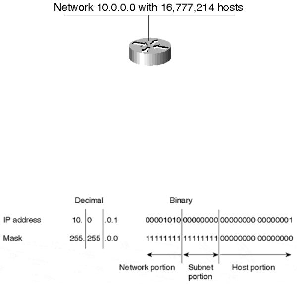
In Figure 3-4, the network mask 255.0.0.0 is applied to network 10.0.0.0. The mask in binary notation is a series of contiguous 1s followed by a series of contiguous 0s. The 1s portion represents the network portion of the address, and the 0s represent the host portion. This provides a mechanism to split the IP address of host 10.0.0.1 into a network portion of 10 and a host portion of 1.
Figure 3-4. Basic Network Masking
Class A, B, and C addresses each have what is referred to as a natural mask, which is the mask created by the very definition of the network and host portions of each class. The natural masks for Class A, B, and C addresses are as follows:
•Class A natural mask is 255.0.0.0
•Class B natural mask is 255.255.0.0
•Class C natural mask is 255.255.255.0
By separating the network and host portions of the IP address, masks facilitate the creation of subnets. Without subnets, network numbers would be very limited in use. Each physical segment, such as an Ethernet, Token Ring, or FDDI segment, is normally associated with one or more network numbers. If subnetting were not available, a Class A network of the form 10.0.0.0 would accommodate only one physical segment with about 16 million hosts on it, as shown in Figure 3-5.
page 56
Internet Routing Architectures, Second Edition
Figure 3-5. Unsubnetted Class A Address Space
With the use of masks, networks can be divided into smaller subnetworks by extending the network portion of the address into the host portion. The subnetting technique provides a larger number of subnetworks while reducing the number of hosts on each network.
In Figure 3-6, a mask of 255.255.0.0 is applied to network 10.0.0.0. This divides the IP address 10.0.0.1 into a network portion of 10, a subnet portion of 0, and a host portion of 1. The 255.255.0.0 mask has borrowed a portion of the host space and has applied it to the network space. As a result, the classful ten-network space has increased from a single large network to 256 subnetworks ranging from 10.0.0.0 to 10.255.0.0. This would decrease the number of hosts per each subnet from 16,777,214 to 65,534.
Figure 3-6. Basic Subnetting
NOTE
Note that in this example, 10.0.0.0 represents the zero subnet. Some legacy router software does not allow the zero subnet address space to be used, nor is it used by default in Cisco routers. In order to enable the use of zero subnets in IOS, you must configure ip subnet-zero.
VLSMs
The term variable-length subnet mask (VLSM) refers to the fact that one network can be configured with different masks. The basic idea behind VLSMs[] is to offer more flexibility in dividing a network into multiple subnetworks while being able to optimally allocate variable amounts of host space among the subnetworks. Without VLSM, only one subnet mask can be applied to an entire network. This would restrict the number of hosts given the number of subnets required. If you select the mask so that you have enough subnets, you might not be able to allocate enough host numbers in each subnet. The same is true of hosts; a mask that allows enough hosts might not provide enough subnet space. VLSM provides the capability to
page 57

Internet Routing Architectures, Second Edition
allocate subnetworks with variable numbers of hosts, allowing the network administrator to better utilize the address space.
Suppose, for example, that you are assigned a Class C network 192.214.11.0 and you need to divide it into three subnets. One subnet will require 100 host numbers, and the other two will require 50 host numbers each. Ignoring the two network end limits of 0 (network number) and 255 (directed broadcast address), you theoretically have 256 host numbers available, 192.214.11.0 through 192.214.11.255. The desired subnet division cannot be accomplished without VLSM, as you will see.
To determine the available subnet options associated with the 192.214.11.0 network, you first need to identify the network mask, which in the case of this traditional Class C network is represented by 255.255.255.0 (all 1s in the first three octets). A handful of subnet masks of the form 255.255.255.X can be used to divide the Class C network 192.214.11.0 into more subnets. A mask must have a contiguous number of 1 bits, starting from the leftmost bit, and the remaining bits must be 0s.
NOTE
Initially, masks were not required to be a contiguous group of 1s followed only by 0s. For example, some implementations used the "middle bits" to identify the host portion of the address and the low-order bits to identify the subnetwork. Although this flexibility provided little benefit to network administrators, it introduced a significant amount of complexity to routing. Because of this complexity, the specification was updated to require that the mask be a contiguous group of 1s.
Table 3-3 lists potential masks that could be used to segment the 256 available addresses into additional subnets.
Table 3-3, Potential Class C Subnets
Last Octet |
Binary Representation |
Number of Subnets |
Number of Hosts[*] |
128 |
1000 0000 |
2 |
128 |
192 |
1100 0000 |
4 |
64 |
224 |
1110 0000 |
8 |
32 |
240 |
1111 0000 |
16 |
16 |
248 |
1111 1000 |
32 |
8 |
252 |
1111 1100 |
64 |
4 |
[*] Note that the Number of Hosts field includes the network number and directed broadcast addresses.
Prior to VLSM, a traditional network would have to be divided using a single contiguous netmask over the whole network. In this case, you have the choice of using a mask 255.255.255.128 and dividing the address into two subnets with 128 hosts each or using 255.255.255.192 and dividing the addresses into four subnets with 64 hosts each. Neither of these options will accommodate the requirement of having 100 hosts on one segment and 50 hosts on each of the other two segments.
By using variable-length masks, you can accomplish the stated goal. For example, assume you have been given network 192.214.11.0. First, use the mask 255.255.255.128 to divide the network address into two subnets with 128 hosts each. These two subnets would be
page 58
Internet Routing Architectures, Second Edition
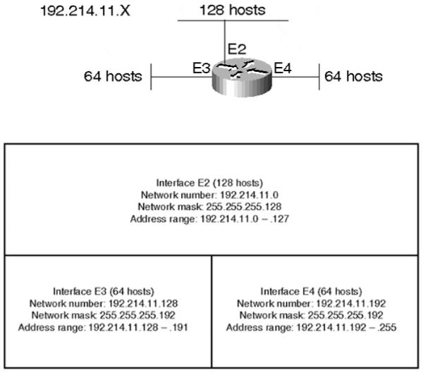
represented as 192.214.11.0 (.0 to .127), the bottom half of the Class C network, and 192.214.11.128 (.128 to .255), the top half of the Class C network. Next, further subnet the 192.214.11.128 network using a mask of 255.255.255.192, creating two subnets with 64 hosts each—subnet 192.214.11.128 (.128 to .191) and subnet 192.214.11.192 (.192 to .255). Figures 3-7 and 3-8 illustrate how to divide the address space accordingly. (Note that the network number and directed broadcast addresses are included in the host counts.)
Figure 3-7. Example of a Class C Network Divided into Three Subnets
Figure 3-8. Use of VLSM to Split Network Space into Subnets of Unequal Size
Of course, not all routing protocols can support VLSM. Routing Information Protocol version 1 (RIP-1) and Interior Gateway Routing Protocol (IGRP) do not carry network masks in routing updates and hence cannot correctly deal with variably subnetted networks. Today, even with the deployment of routing protocols such as Open Shortest Path First (OSPF), Enhanced IGRP (EIGRP), Routing Information Protocol version 2 (RIP-2), and Intermediate System-to-Intermediate System (IS-IS), which do support VLSM, administrators still have difficulties adapting to this technique. Most early networks built on RIP-1 and IGRP do not have their IP addresses allocated in a manner that would enable them to be more optimally grouped into blocks. Rather, their IP addresses are scattered, and administrators would have to renumber their hosts to make them conform to the new addressing scheme. Such renumbering is difficult, and administrators often consider it out of the question. This coexistence is a
page 59