

Internet Routing Architectures, Second Edition
Chapters 11 and 12 are not intended to replace Cisco manuals and do not cover every command and scenario. They present configurations for common situations that are encountered in connecting networks to the Internet. Your particular network might require a combination of scenarios—or a different approach—to achieve the most effective policies.
In the following discussions, an AS could play the role of a customer, provider, or both. Do not get confused by having AS numbers and AS roles switched around, or by IP address numbering not being too realistic. These are just exercises that will help you understand BGP so that you can apply it accordingly in your own environment.
Building Peering Sessions
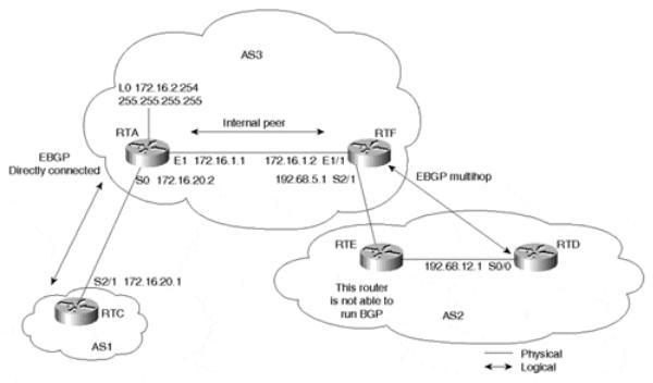
This example demonstrates the different types of BGP peering sessions you will encounter. Consider Figure 11-1.
Figure 11-1. Building Peering Sessions
An IBGP peering session is formed within AS3, between RTA's loopback address and RTF's physical address. EBGP sessions are also formed between AS3 and AS1 by using the two directly connected IP addresses of RTA and RTC. Another EBGP session is formed between RTF in AS3 and RTD in AS2, using IP addresses that are not on the same segment (multihop).
It is important to remember that the BGP TCP connection will not become established unless there is IGP connectivity between the two peers or the two peers are directly connected. We will use OSPF as an IGP to establish the required underlying connectivity internally. Example 11-1 shows the configuration for RTA.
page 267
Internet Routing Architectures, Second Edition
Example 11-1. RTA Configuration
ip subnet-zero interface Loopback0
ip address 172.16.2.254 255.255.255.255 interface Ethernet1
ip address 172.16.1.1 255.255.255.0 interface Serial0
ip address 172.16.20.2 255.255.255.0 router ospf 10
network 172.16.0.0 0.0.255.255 area 0 router bgp 3
no synchronization
neighbor 172.16.1.2 remote-as 3
neighbor 172.16.1.2 update-source Loopback0 neighbor 172.16.20.1 remote-as 1
no auto-summary ip classless
The configuration for RTA in Example 11-1 shows some syntax that might be unfamiliar to you. All the syntax is explained in Table 11-1 generically, as well as in relation to the particular routing scenario of Figure 11-1. In subsequent examples throughout this chapter, however, the router's configuration focus on the relevant commands required to configure BGP, the IGP, or static routing. Commands that assign IP addresses to interfaces will be omitted in many instances due to space limitations.
|
Table 11-1. Example 11-1 Configuration Commands |
Command |
Explanation |
ip subnet-zero |
This global configuration command is necessary in case you are configuring interfaces |
|
that fall in subnet-zero subnets (that is, 192.168.1.0/30). With the introduction of classless |
|
routing, using subnet-zero is very common and is a recommended default configuration. |
interfacetype |
This command configures an interface type and number on the router. Any configuration |
slot/port |
that appears under the command will be specific to that particular interface. (The actual |
|
slot/port syntax might vary slightly across different platforms.) Note that RTA has three |
|
interface commands—one for each of its three connections. The loopback interface is a |
|
software-only interface that emulates an interface that is always up. |
ip addressip-address |
This is an interface command that configures an interface with an IP address/mask tuple. |
mask [secondary] |
RTA's Ethernet IP address, for example, is configured by ip address 172.16.1.1 |
|
255.255.255.0. |
routerprocess |
This is a global command that defines a process such as OSPF, RIP, or BGP and gives the |
[process-id] |
process a process ID. Some processes, such as RIP, do not require a process ID. For |
|
example, in RTA's configuration, router ospf 10 indicates an OSPF process with ID 10, |
|
whereas router bgp 3 indicates a BGP process in autonomous system 3. |
network |
This command indicates the networks or, in the case of OSPF, the interfaces that will |
|
participate in a specific routing process. |
inverse mask |
In RTA's network command, you will notice a representation of the form 0.0.255.255— |
|
basically, a number of 0s followed by a number of 1s. This is an inverse mask, in which |
|
the 0s are an exact match, and the 1s are referred to as do-not-care bits. For example, |
|
172.16.0.0 0.0.255.255 indicates any IP address or network of the form 172.16.X.X. |
|
Inverse masks can be applied to access lists as well as the network command. Table 11-2 |
|
provides a dotted decimal/inverse mask reference chart. |
area area-number |
This represents an OSPF area with a specified area number. |
neighbor |
This command is used to define the BGP neighbor connection parameters and policies |
|
between this router and its peers. In RTA's configuration, neighbor 172.16.1.2 remote-as |
|
3 indicates that a BGP peer session is to be established between RTA and peer 172.16.1.2 |
|
in autonomous system 3. |
page 268
Internet Routing Architectures, Second Edition
no synchronization This command turns off the synchronization between BGP and IGP, as explained in Chapter 6, "Tuning BGP Capabilities."
no auto-summary This command turns off the BGP classful automatic summarization at the major net |
||
|
boundary. Without this command, BGP will not send the subnets of a major net that are |
|
|
redistributed into BGP. In other words, updates about 172.16.1.0/24, 172.16.2.0/24, and |
|
|
so on will be sent as a single major class B 172.16.0.0/16. Summarization at the major net |
|
|
boundary should be done only if the AS owns the whole major net. Unless summarization |
|
|
is explicitly required, the recommended configuration is to disable it. |
|
ip classless |
This command lets the router forward packets that are destined for unrecognized subnets |
|
|
of directly connected networks. By default, when a router receives packets for a subnet |
|
|
that falls numerically within its subnetwork addressing scheme, if there is no such subnet |
|
|
number in the routing table and there is no network default route, the router discards the |
|
|
packets. When the ip classless command is enabled, however, the router forwards those |
|
|
packets to the best supernet route. Unless classful behavior is explicitly required, the |
|
|
recommended configuration is to disable it. |
|
update-source |
This command, when associated with the BGP neighbor statement, specifies the interface |
|
interface |
to be used as a source IP address of the BGP session with the neighbor. In RTA's |
|
|
configuration, for example, the second neighbor statement indicates that Loopback 0 is to |
|
|
be used as a source IP address. |
|
remote-as |
This command, when associated with the BGP neighbor statement, specifies the AS |
|
|
number of the remote BGP peer. In RTA's configuration, the first neighbor statement |
|
|
indicates that the internal BGP neighbor 172.16.1.2 belongs to the local AS3. The third |
|
|
neighbor statement indicates that the external BGP peer 172.16.20.1 belongs to AS1. |
|
|
|
|
|
Table 11-2. CIDR-to-Dotted Decimal Notation Chart |
|
CIDR |
Dotted Decimal |
Inverse Dotted Decimal |
/1 |
128.0.0.0 |
127.255.255.255 |
/2 |
192.0.0.0 |
63.255.255.255 |
/3 |
224.0.0.0 |
31.255.255.255 |
/4 |
240.0.0.0 |
15.255.255.255 |
/5 |
248.0.0.0 |
7.255.255.255 |
/6 |
252.0.0.0 |
3.255.255.255 |
/7 |
254.0.0.0 |
1.255.255.255 |
/8 |
255.0.0.0 |
0.255.255.255 |
/9 |
255.128.0.0 |
0.127.255.255 |
/10 |
255.192.0.0 |
0.63.255.255 |
/11 |
255.224.0.0 |
0.31.255.255 |
/12 |
255.240.0.0 |
0.15.255.255 |
/13 |
255.248.0.0 |
0.7.255.255 |
/14 |
255.252.0.0 |
0.3.255.255 |
/15 |
255.254.0.0 |
0.1.255.255 |
/16 |
255.255.0.0 |
0.0.255.255 |
/17 |
255.255.128.0 |
0.0.127.255 |
/18 |
255.255.192.0 |
0.0.63.255 |
/19 |
255.255.224.0 |
0.0.31.255 |
/20 |
255.255.240.0 |
0.0.15.255 |
/21 |
255.255.248.0 |
0.0.7.255 |
/22 |
255.255.252.0 |
0.0.3.255 |
/23 |
255.255.254.0 |
0.0.1.255 |
/24 |
255.255.255.0 |
0.0.0.255 |
/25 |
255.255.255.128 |
0.0.0.127 |
page 269

Internet Routing Architectures, Second Edition
/26 |
255.255.255.192 |
0.0.0.63 |
/27 |
255.255.255.224 |
0.0.0.31 |
/28 |
255.255.255.240 |
0.0.0.15 |
/29 |
255.255.255.248 |
0.0.0.7 |
/30 |
255.255.255.252 |
0.0.0.3 |
/31 |
255.255.255.254 |
0.0.0.1 |
/32 |
255.255.255.255 |
0.0.0.0 |
We turn now to RTF's configuration in Example 11-2.
Example 11-2. RTF Configuration
ip subnet-zero interface Ethernet1/1
ip address 172.16.1.2 255.255.255.0 interface Serial2/1
ip address 192.68.5.1 255.255.255.0 router ospf 10
network 172.16.0.0 0.0.255.255 area 0 network 192.68.0.0 0.0.255.255 area 0 router bgp 3
no synchronization
neighbor 172.16.2.254 remote-as 3 neighbor 192.68.12.1 remote-as 2 neighbor 192.68.12.1 ebgp-multihop 2 no auto-summary
ip classless
In RTF's configuration, you can see the ebgp-multihop 2 command being used as part of the neighbor configuration. This indicates that the exterior BGP peer is not directly connected and can be reached at a maximum of two hops away. Remember that ebgp-multihop is applicable with only EBGP, not IBGP. Also, the value at the end (2 in this example) represents the TTL (Time To Live) value to be configured in the IP packet header. Example 11-3 and Example 11-4 show the configurations for RTC and RTD, respectively.
Example 11-3. RTC Configuration
ip subnet-zero interface Serial2/1
ip address 172.16.20.1 255.255.255.0 router bgp 1
neighbor 172.16.20.2 remote-as 3 no auto-summary
ip classless
Example 11-4. RTD Configuration
ip subnet-zero interface Serial0/0
ip address 192.68.12.1 255.255.255.0 router ospf 10
network 192.68.0.0 0.0.255.255 area 0 router bgp 2
neighbor 192.68.5.1 remote-as 3
page 270