

Internet Routing Architectures, Second Edition
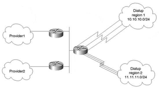
Figure 8-10. Balancing Dialup Traffic Based on Source
Dialup users accessing a certain point of presence can be directed toward certain providers based on their source IP address. As illustrated in Figure 8-10, dialup users in region 1 can be directed toward Provider1, whereas dialup users from region 2 can be directed toward Provider2.
Policy routing should not replace dynamic routing, but instead should complement it. Policy routing has its own set of drawbacks:
•Extra static configuration is needed to identify sources of traffic or a combination of source and destination. Care should be taken not to disrupt other traffic and to specify other alternatives for traffic in case of backup situations.
•Policy routing is CPU-intensive because it is based on the source IP addresses, unlike dynamic and static routing, which are based on the destination IP addresses. Sophisticated caching and switching techniques have been implemented all along based on the traffic's destination. Most implementations have not yet optimized routing and caching techniques based on the source of the IP packet. As such, policy routing takes additional CPU cycles to detect source addresses. This behavior should change as implementations attain a better understanding of IP traffic flows that let caches keep track of source and destination information. This new caching methodology would alleviate routers from disruptive processing on matching sources of IP traffic and make policy routing much more effective and practical.
Looking Ahead
Autonomous systems can grow in size beyond the control of administrators. Service providers might find themselves with a large internal BGP mesh that is both cumbersome and inefficient to control. On the other hand, enterprise networks might grow in a manner that causes internal gateway protocols to struggle in keeping up with instabilities. Controlling large-scale autonomous systems lies in the art of dividing these large domains into smaller, more manageable entities. The following chapter offers concepts and techniques that can help
page 229
Internet Routing Architectures, Second Edition
providers and customers apply architectural designs to achieve structured routing inside their domains.
Frequently Asked Questions
Q—
I am not running IBGP between my border routers. Do I need to worry about routing loops?
A—
As far as the interaction between IGP and BGP, loops cannot occur. If your internal routers are following a default toward the BGP border routers, after the traffic reaches the border router, it has only one way out via the EBGP session.
Q—
I have two BGP border routers running IBGP and connected via a serial link. I am using local preference to control my exit points. What happens if the serial line goes down?
A—
If you are setting BGP policies that cause traffic to be directed between BGP border routers, this would be the same scenario as if you did not have a link between the border routers. While the serial line is down, your traffic might end up looping inside the AS.
Q—
If I use a serial link between my IBGP border routers to direct traffic from one router to the other, should that link be as fast as my links to my providers?
A—
The only traffic that line will carry is outbound traffic that is redirected between border routers and a portion of incoming traffic. Try to figure out what percentage of your total traffic that constitutes to estimate the appropriate link bandwidth.
Q—
I need to direct traffic toward destination X over my serial line and toward destination Y over my Ethernet line. Can I do that via policy routing?
A—
What you have just described can be done via static routing, which works based on destination. There is no need for policy routing, which works based on source or source and destination combined.
page 230
Internet Routing Architectures, Second Edition
Q—
Do I apply policy routing over my outbound or inbound router interface?
A—
Policy routing checks source addresses coming into an interface. Configure on the inbound interface.
page 231
Internet Routing Architectures, Second Edition
Chapter 9. Controlling Large-Scale Autonomous
Systems
This chapter covers the following key topics:
•Route reflectors—
A method of managing expanding mesh requirements in large autonomous systems (ASs) by using selected routers as focal points for internal BGP sessions.
•Confederations—
A method of managing expanding mesh requirements in large ASs by creating subASs.
•Controlling IGP expansion—
Methods of managing networks in which expansion is characterized by the use of multiple IGPs.
Autonomous systems consisting of hundreds of routing nodes can pose a serious routing management problem to network administrators. Service providers and customers each have their own set of problems when dealing with large networks. On the service provider side, the majority of routers run Border Gateway Protocol (BGP). Because of the BGP rule that states that one Interior Border Gateway Protocol (IBGP) speaker can't advertise a route learned from another IBGP speaker to a third IBGP speaker, the IBGP mesh can quickly grow beyond the provider's control. On the customer side, however, the majority of routers run Interior Gateway Protocols (IGPs), which also might grow beyond the customer's control.
This chapter discusses methods and techniques that can be used to better control the deployment of BGP and IGPs inside large autonomous systems. There are no absolute rules that say a provider or customer should or should not use one of the methods discussed in this chapter, or which method is best. Keep in mind that any new technique brings with it its own complexities. Imposing complex techniques on situations that do not really need them could hurt more than help, but in contrast, planning ahead can save you a considerable number of headaches down the road.
Route Reflectors
In some Internet service provider (ISP) networks, the internal BGP mesh can become quite large (more than 100 internal BGP sessions per router), which strongly suggests that some new peering mechanism be implemented. The route reflector[] concept is based on the idea of specifying a concentration router to act as a focal point for internal BGP sessions. Multiple (client) BGP routers can peer with a central server (the route reflector), and then route reflectors peer with one another. Although the BGP rule states that routes learned via one IBGP speaker can't be advertised to another IBGP speaker, route reflection allows the route reflector servers to "reflect" routes as described later, thereby relaxing the IBGP full-mesh constraints.
page 232
Internet Routing Architectures, Second Edition
Route reflectors are recommended only for ASs that have a large internal BGP mesh. The route reflector concept introduces processing overhead on the route reflector server and, if configured incorrectly, might introduce routing loops and routing instability. As a result, route reflectors are not recommended for every topology.
That said, route reflection does introduce some advantages on both the route reflector servers and their clients. For example, a route reflector server implementation could be optimized to simply copy UPDATE messages when sending to multiple peers, rather than generating unique messages per peer. In addition, the clients normally peer with only the local route reflector server, thereby significantly decreasing the number of sessions they're required to maintain.
TIP
See the section "Route Reflectors" in Chapter 12.
Internal Peers Without Route Reflectors
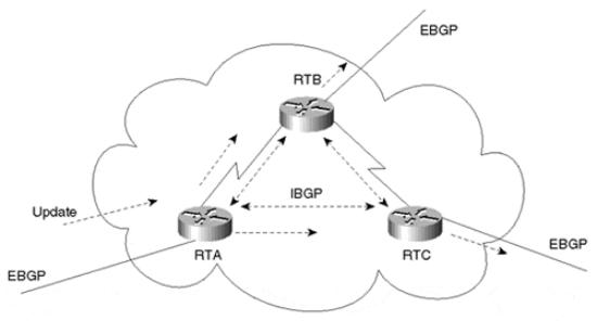
Without route reflectors, BGP speakers in an AS will have a logical full mesh. We discussed this behavior earlier in this book; the following illustration is just a reminder. In Figure 9-1, RTA, RTB, and RTC form an internal BGP logical full mesh. Each router acts as a BGP peer with the other two routers. RTA and RTB are physically connected, as are RTB and RTC. No physical connection exists between RTA and RTC.
Figure 9-1. Internal Peers in a Normal Full-Mesh Environment
When RTA receives an update from an external peer, it forwards the update to its two internal peers, RTB and RTC. Note that although there is no physical connectivity between RTA and RTC, RTA manages to pass the update to RTC via the BGP peering session. RTB and RTC, in turn, pass the update to their external peers.
page 233
Internet Routing Architectures, Second Edition
The UPDATE message that RTB receives from RTA is not readvertised to RTC because RTC is an internal peer, and the UPDATE message RTB received was from an internal peer (RTA). Without the internal BGP session between RTA and RTC, RTC would never get the update; hence, the full IBGP mesh is required.
Internal Peers with Route Reflectors
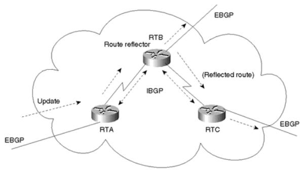
The route reflector acts as a concentration point for other routers referred to as clients. The clients peer with the route reflector and exchange routing information with it. In turn, the route reflector passes (or reflects) the information between clients and to other IBGP and Exterior Border Gateway Protocol (EBGP) peers.
In Figure 9-2, RTB is configured as a route reflector with two clients, RTA and RTC. RTA gets an update from an external peer and forwards it to RTB. RTB reflects the update from client RTA to client RTC. In this configuration, a peering session between RTA and RTC should not be configured, because the route reflector is propagating the BGP information from RTA to RTC.
Figure 9-2. Internal Peers Using a Route Reflector
In an AS where the administrator would have to build a substantial number of BGP sessions between routers, the route reflector concept provides a very helpful and scalable solution to the problem.
Naming Conventions and Rules of Operation
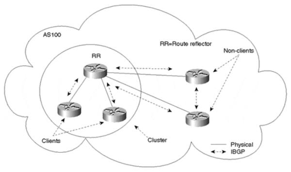
The route reflector is a router that performs the route reflection function. The IBGP peers of the route reflector fall under two categories—clients and nonclients. A route reflector and its clients form a cluster. All peers of the route reflector that are not part of the cluster are nonclients. Figure 9-3 illustrates these components.
page 234
Internet Routing Architectures, Second Edition
Figure 9-3. Route Reflection Process Components
Nonclients (standard IBGP speakers) are still required to be fully meshed with one another and the route reflector because they follow the normal IBGP advertisement rules, although they no longer need to peer with the clients of the route reflectors. Clients should not peer with internal speakers outside their associated cluster. As you can see, these conditions have been met for the clients and nonclients in Figure 9-3.
The route reflector function is implemented only on the route reflector; all clients and nonclients are normal BGP peers that have no notion of the route reflector. Route reflector clients are considered as such only because the route reflector lists them as clients.
Any route reflector that receives multiple routes for the same destination employs the usual BGP decision process to pick the overall best path. The best path would be propagated inside the AS based on the following rules of operation:
•If the route is received from a nonclient peer, reflect to clients only.
•If the route is received from a client peer, reflect to all nonclient peers and also to client peers.
•If the route is received from an EBGP peer, reflect to all client and nonclient peers.
Because route reflection is a concept that applies only internally to an AS, routers external to the AS, which would receive UPDATEs via EBGP, are considered nonclients and follow normal nonclient behavior with respect to sending and receiving UPDATEs.
Redundancy Issues and Multiple Route Reflectors in an AS
With the lack of a full BGP mesh inside the AS, redundancy and reliability become issues. If a route reflector fails, clients will be isolated. Redundancy requires the existence of multiple
page 235
Internet Routing Architectures, Second Edition
route reflectors in a cluster where clients can simultaneously peer with multiple routers. If one route reflector fails, the other(s) should still be available.
The importance of complementing logical redundancy with physical redundancy cannot be overstated. It does not make sense to build route reflector redundancy if the physical redundancy itself does not exist. The logical redundancy arrangement on the left in Figure 9-4 shows RTA as the client of both RR1 and RR2. (RR stands for route reflector in this figure and those that follow.) RTA is peering with both route reflectors in an effort to create a redundant link. Unfortunately, if the connection to RR1 is broken, or if RR1 itself fails, RTA is isolated. The logical connectivity between RTA and RR2 is of no practical use; it is simply more memory and processing overhead.
Figure 9-4. Comparison of Logical and Physical Redundancy Solutions
The physical redundancy configuration on the right in Figure 9-4 illustrates how logical redundancy can be backed up with physical redundancy. In the event of a failure in the link to RR1, RTA can reach RR2.
Route Reflection Topology Models
National networks are usually laid out in concentration points across geographical regions. Providers have points of presence (POPs), sometimes called hubs, in different regions in the U.S. with high-speed links connecting different locations in a partial-mesh topology. The route reflector concept can be used to logically interconnect the routers running BGP in a pattern that follows the physical topology. Figure 9-5 illustrates a complex arrangement featuring route reflectors.
page 236
Internet Routing Architectures, Second Edition
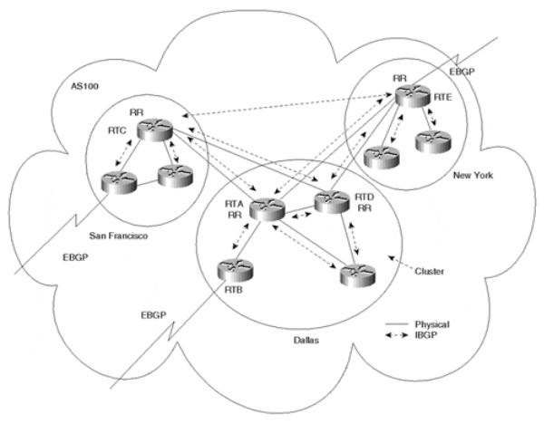
Figure 9-5. Complex Multiple Route Reflector Environment
Except for the fact that the route reflector needs to keep up with more IBGP sessions than client routers, any router could be configured as a route reflector. Your physical topology should be the main indicator of which router would be the best route reflector. Also, because the clients aren't required to peer with lots of other IBGP routers, more resources are available for handling EBGP connections.
In Figure 9-5, AS100 is divided into three clusters: San Francisco, Dallas, and New York. The Dallas cluster has multiple RRs for redundancy. RTA and RTD physically connect San Francisco to New York. It makes sense to follow the actual physical traffic flow in selecting RRs, so RTA and RTD are the obvious choices for RRs in the Dallas cluster.
In San Francisco, router RTC physically connects San Francisco to Dallas, so RTC would be the best candidate to become a RR. The same reasoning applies for the New York cluster: RTE physically connects New York to Dallas and is the best candidate for a RR.
The Route Reflector Preserves IBGP Attributes
The route reflector concept does not change IBGP behavior—the route reflector is not allowed to modify the attributes of the reflected IBGP routes. The NEXT_HOP attribute, for example, remains the same when an IBGP route is exchanged between RRs. This is necessary to avoid loops inside the AS.
page 237
Internet Routing Architectures, Second Edition
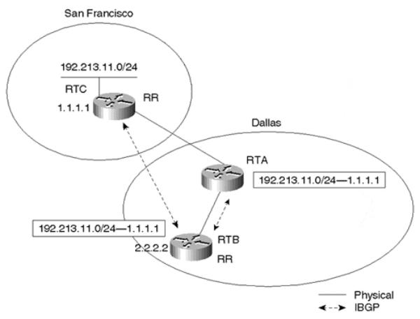
Figure 9-6 illustrates why the RR should not modify the attributes of the reflected IBGP routes. The NEXT_HOP attribute is used as an example. Figure 9-6 focuses on the portion of the network where Dallas connects to San Francisco.
Figure 9-6. The Route Reflector Preserves IBGP Attributes
Although the route reflection rules state that a route reflector should not modify any of the attributes, many implementations do permit this and/or filtering to occur. In practice, use care if you must perform actions of this nature.
Assume that RTB rather than RTA is specified as the route reflector and that an IBGP session is configured between RTB (2.2.2.2) and RTC (1.1.1.1). This looks odd, because RTA is physically passing the traffic, while logically RTB is reflecting the BGP routes between RTA and RTC. RTB will receive the prefix 192.213.11.0/24 from its IBGP neighbor RTC with a next hop of 1.1.1.1. RTB will reflect the route to its client RTA with the next hop 1.1.1.1 also. This is the standard, desired behavior for route reflection.
On the other hand, if RTB were to change the next hop to its IP address, 2.2.2.2, RTA would try to use RTB to reach destination 192.213.11.0/24. A loop would occur between RTA and RTB, because RTA will use the next hop of RTB. The result is that RTA will forward traffic to RTB. Subsequently, RTB will forward the traffic back to RTA to reach the final destination. This hypothetical situation exemplifies why the route reflector must not change IBGP attributes.
page 238
Internet Routing Architectures, Second Edition
It is worth mentioning again that route reflectors propagate only the best route to a given destination. In other words, if a route reflector learns the same prefix from multiple client peers, only one path will be propagated to other peers. Therefore, when route reflectors are used, the number of paths available to reach a given destination will likely be lower than that of a full-mesh configuration. Due to this behavior, it is again advised that route reflector topologies resemble that of the physical topology, or the potential for suboptimal routing might occur.
Avoiding Loops
BGP relies on the information in the AS path to facilitate loop detection. A BGP update that attempts to reenter the AS it was originated from will be dropped by the border router of the source AS.
With the introduction of route reflectors, there is a potential for routing loops within an AS. A routing update that leaves a cluster may reenter the cluster. Loops inside the AS cannot be detected by the traditional AS path approach because routing updates do not have an originating AS path signature. Therefore, when route reflectors are deployed, BGP offers two extra measures for loop avoidance inside the AS—using an ORIGINATOR_ID and using a CLUSTER_LIST.
Using an ORIGINATOR_ID
The ORIGINATOR_ID is a 4-byte, optional, nontransitive BGP attribute (type code 9). This attribute carries the ROUTER_ID of the route's originator in the local AS and is to be added to the UPDATE message by the route reflector. If the update comes back to the originator because of poor configuration, the originator should discard it.
The CLUSTER_LIST
The CLUSTER_LIST is an optional, nontransitive BGP attribute (type code 10). Each cluster is represented with a CLUSTER_ID.
A CLUSTER_LIST is a sequence of CLUSTER_IDs that contain path information regarding the list of clusters that an UPDATE has traversed. When a route reflector sends a route from its clients to nonclients outside the cluster, it appends the local CLUSTER_ID to the CLUSTER_LIST, or creates the list if one is not present. If the route reflector receives an UPDATE whose CLUSTER_LIST contains the local CLUSTER_ID value, the UPDATE message should be discarded. Thus, the CLUSTER_LIST provides loop avoidance inside an AS, whereas the AS_PATH list, discussed earlier, facilitates loop avoidance for UPDATEs traversing multiple, external ASs.
See the configuration guidelines in the section "Route Reflectors" in Chapter 12.
Route Reflectors and Peer Groups
Recall from Chapter 6, "Tuning BGP Capabilities," that a peer group is a group of BGP neighbors that share similar routing policies. Previously, route reflectors could be used only in conjunction with peer groups when all route reflector clients within a cluster were fully meshed. The reason can best be described through the following example. In a typical route reflection situation, Router A learns a prefix from Router B. Subsequently, Router A sends an
page 239
Internet Routing Architectures, Second Edition
UPDATE message containing WITHDRAWN ROUTES information back to Router B to poison that route. In other words, Router A informs Router B that this prefix is unreachable via A. This prevents a route loop situation in which A claims that a prefix is reachable via B, and B claims it is reachable via A.
In a peer group, the same UPDATE message (with subsequent WITHDRAWN ROUTES information) is sent to all members of the group. In a peer group/route reflector situation, a route reflector that learns a prefix from one of the clients and attempts to poison that route ends up withdrawing that prefix from all the other clients. Because the clients are not talking to one another via BGP, that prefix is lost. Therefore, an IBGP mesh between the clients of a route reflector is necessary so that other clients will learn the prefix directly from the originator. Even with this design, the network administrator avoids building a full IBGP mesh between all IBGP routers in the AS by concentrating the mesh between route reflectors and clients (versus between clients within a cluster).
Fortunately, IOS has removed the full-mesh requirement on route reflector clients. Currently, clients of a route reflector configured under a peer group are not required to be fully meshed.
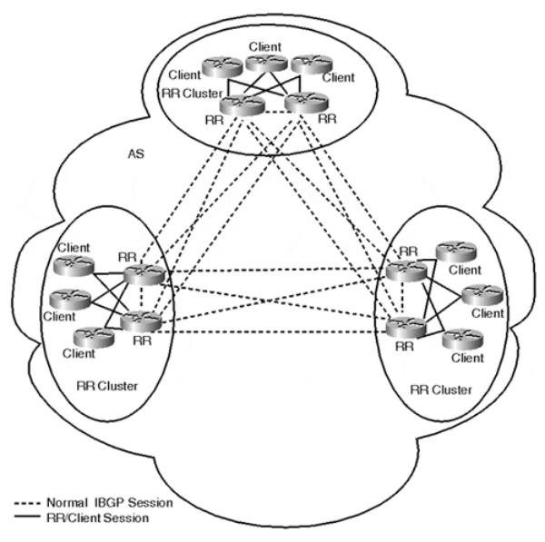
With the use of peer groups, the AS design would look like rings of fully meshed BGP speakers. Route reflectors are fully meshed among each other, and clients are only required to peer with the route reflectors. Figure 9-7 illustrates such an environment; each circled area represents a distinct peer group and route reflector cluster. In contrast, Figure 9-8 demonstrates what would be required without the use of route reflectors.
page 240
Internet Routing Architectures, Second Edition
Figure 9-7. Typical BGP Route Reflection Topology
page 241