

Internet Routing Architectures, Second Edition
Assume also that AS1 is very careful about injecting defaults. The SF router will never inject a default if the SF link is down, and the NY router will never inject a default if the NY link is down. All is well and working great until provider AS2 starts advertising metrics (MED) toward AS1.
Assume in Figure 8-5 that AS2 is sending its updates toward AS1 with the internal IGP metrics as the MED values. AS1 receives the same networks on both the SF and NY links with different MED values. For each network, BGP follows the path with the lowest metric. If, for example, RTC receives network 192.213.16.0/24 with MED 50 on the SF link and MED 20 on the NY link, RTC will prefer the NY link. This would mean that to reach 192.213.16.0/24, RTA might follow the interior default toward RTC and then be instructed to instead go toward RTD. Similarly, RTB might follow a default toward RTD and then be directed toward RTC. In both cases, a loop will occur.
As you can see, the exit point for all networks cannot be predetermined as in the primary/backup case. To deal with this situation, you have the following options:
•Ignore the MED and base the routing on a primary/backup scenario.
•Have a shorter path connection between RTC and RTD so that traffic redirected between exit points follows the shortest path between the IBGP routers.
•Run an IBGP mesh between RTA, RTB, RTC, and RTD.
Other normal situations can also cause loops. You could end up in a looping situation whenever you have multiple links and you are running defaults inside the AS. If you are connected to two providers, you might prefer some destinations via one provider and others via the second provider. If your IGP is following defaults, you might end up at the wrong exit point with no way to go back.
As you can see by now, the solution to looping problems is to either have BGP and IGP be more deterministic about where to exit the AS or prevent traffic between IBGP routers from going back over IGP-only routers. The more you are aware of your traffic behavior, the better you can avoid loop situations.
Policy Routing
Policy routing is a means of controlling routes that rely on the source, or source and destination, of traffic rather than destination alone. Policy routing can be used to control traffic inside an AS as well as between ASs. Policy routing is a glorified form of static routing. It is used when you want to force a routing behavior different from what the dynamic routing protocols dictate.
Static routing lets you direct traffic based on the traffic destination. Traffic toward destination 1 can be transmitted via point A, and traffic toward destination 2 can be transmitted via point B.
Policy routing, on the other hand, lets you direct traffic based on traffic source or a combination of source and destination (or perhaps even other attributes) rather than standard destination-based routing. Traffic originating from network 1 can be transmitted via point A, or traffic originating from network 1 destined for network 2 can be transmitted via point B.
page 225
Internet Routing Architectures, Second Edition
TIP
See Example 12-6, "Policy Routing".
The following sections examine policy routing based on traffic source and traffic source/destination, as well as the other applications of policy routing.
Policy Routing Based on Traffic Source
Consider the example shown in Figure 8-6. Assume that AS1 was assigned network numbers from two different providers. The 10.10.10.0/24 range was taken from AS3, and the 11.11.11.0/24 range was taken from AS4. AS1 wants to have any traffic originated from its 10.10.10.0/24 networks to be directed toward AS3 and traffic from its 11.11.11.0/24 networks to be directed to AS4, irrespective of the traffic's final destination. AS1 could use policy routing to achieve this requirement by forcing all traffic with a source IP address belonging to 10.10.10.0/24 to have a next hop of 1.1.1.1 and traffic with a source IP belonging to 11.11.11.0/24 to have a next hop of 2.2.2.2.
Figure 8-6. Policy Routing Scenario Based on Source
Policy Routing Based on Traffic Source/Destination
Policy routing can also be based on a source/destination combination, as illustrated in Figure 8-7.
page 226
Internet Routing Architectures, Second Edition
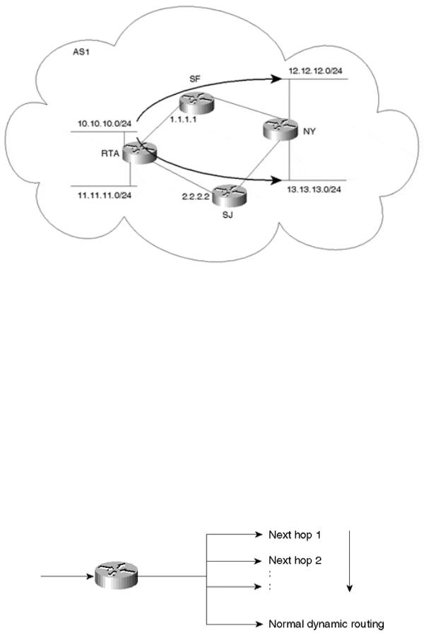
Figure 8-7. Policy Routing Scenario Based on Source and Destination
Assume that RTA wants to use the SF link for any traffic originating from network 10.10.10.0/24 and reaching network 12.12.12.0/24 in NY. Also, RTA wants to use the SJ link for any traffic originating from network 10.10.10.0/24 and reaching network 13.13.13.0/24 in NY. Policy routing can be used to set the next hop for the traffic combination (source = 10.10.10.0/24, destination = 12.12.12.0/24) to be 1.1.1.1. The traffic combination (source = 10.10.10.0/24, destination = 13.13.13.0/24) will trigger the next hop to be set to 2.2.2.2.
Policy Routing Defaults to Dynamic Routing
Whenever static behavior is enforced, backup becomes an issue. It is important to make sure that if policy-routed traffic cannot be delivered because the next hop is down, some other alternative is available. Cisco offers a creative way of executing policy routing by offering multiple next hops for policy-routed traffic. If the first next hop is down or unavailable, the second next hop is tried, and so on. If none of the statically defined next hops are available, the router can be configured to send traffic according to the normal dynamic routing (that is, based on destination), as illustrated in Figure 8-8.
Figure 8-8. Policy Routing Defaults to Dynamic Routing
page 227
Internet Routing Architectures, Second Edition
Other Applications of Policy Routing
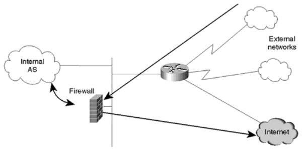
One practical application of policy routing is its use with firewalls. Firewalls are devices that apply security requirements to traffic. Firewall implementations include packet filtering, authentication, and encryption. Depending on the network setup, administrators might want to direct some or all incoming (or outgoing) traffic toward a firewall device, as shown in Figure 8-9.
Figure 8-9. Incoming or Outgoing Traffic Can Be Routed to a Firewall
An applicable situation might involve traffic entering an organization through dialup services. Perhaps the organization requires that the dialup users from remote sites pass through a firewall before reaching the Internet. If the firewall is in the traffic trajectory, this is not a problem. Any inbound or outbound traffic will pass through the firewall on its way to a destination. In some cases, however (such as that shown in Figure 8-9), traffic bypasses the firewall in its normal path. Policy routing can be configured on a router bordering external networks to force the incoming dialup traffic to be directed to the firewall. After the firewall applies its policies or encryption, dialup traffic is sent to its final destination.
NOTE
Policy routing does not change the traffic destination. It affects only the next hop to which traffic is directed prior to being sent toward its ultimate destination.
Policy routing can also be used with dialup services for better traffic balancing, as shown in Figure 8-10.
page 228