

Defining a State diagram (построение диаграммы состояний)
Just as we define classes for a Class diagram, it is necessary to define the elements of a State diagram. Let us first see what the elements of a State diagram are.
Elements of a State diagram (Элементы диаграммы состояний)
A State diagram consists of the following behavioral elements:
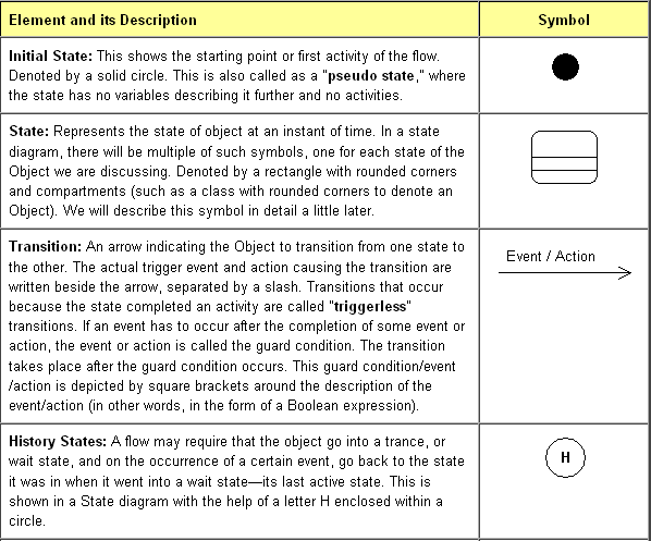
Условные обозначения:
Initial state – начальное состояние;
State – состояние;
Transition – переход;
History states – предыстория состояний;
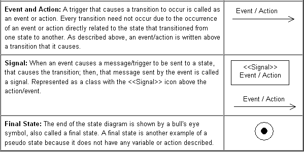
Event and action – событие и действие;
Signal – сигнал.
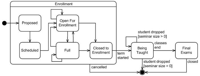
The complete seminar lifecycle (полный жизненный цикл семинара).
Условные обозначения:
Enrollment – запись;
Proposed – предлагаемый;
Scheduled – запланированный;
Full – полный;
Open for enrollment – открыт для записи;
Closed for enrollment – закрыть для записи;
Cancelled – отмена;
Term started – семестр начался;
Being taught – обучение;
Final exams – окончательные экзамены;
Closed – закрыто;
Student dropped – отставание студентов;
Seminar size – объем семинара;
Algorithmic State Machine (алгоритмические конечные автоматы).
The Algorithmic State Machine (ASM) method is a method for designing finite state machines. It is used to represent diagrams of digital integrated circuits. The ASM diagram is like a state diagram but less formal and thus easier to understand. An ASM chart is a method of describing the sequential operations of a digital system.
Метод ASM применяется для разработки конечных автоматов. Он используется для представления схем цифровых ИС. Диаграмма ASM подобна диаграмме состояний, но менее формализованная и более легкая для понимания. Диаграмма ASM является методом описания последовательностных операций цифровых устройств.
The ASM method is comprised of the following steps (метод ASM включает следующие шаги):
1. Create an algorithm, using pseudocode, to describe the desired operation of the device (создание алгоритма с использованием превдокода для описания желаемой операции устройства);
2. Convert the pseudocode into an ASM chart (преобразование превдокода в диаграмму ASM);
3. Design the datapath based on the ASM chart (разработка тракта обработки данных, основываясь на диаграмме ASM);
4. Create a detailed ASM chart based on the datapath (создание детальной диаграммы ASM, исходя из тракта обработки данных);
5. Design the control logic based on the detailed ASM chart (разработка схемы управления логическими элементами, исходя из детальной диаграммы ASM).
Pseudocode is a compact and informal high-level description of a computer programming algorithm that uses the structural conventions of a programming language, but is intended for human reading rather than machine reading.
Псевдокод является компактным и неформальным описанием высокого уровня для алгоритма компьютерной программы, который использует структурные условности языка программирования, но при этом он предназначен скорее для восприятия человеком, чем ЭВМ.
Pseudo-code typically omits details that are not essential for human understanding of the algorithm, such as variable declarations, system-specific code and subroutines. The programming language is augmented with natural language descriptions of the details, where convenient, or with compact mathematical notation. The purpose of using pseudocode is that it is easier for humans to understand than conventional programming language code, and that it is a compact and environment-independent description of the key principles of an algorithm. It is commonly used in textbooks and scientific publications that are documenting various algorithms, and also in planning of computer program development, for sketching out the structure of the program before the actual coding takes place.
A datapath is a collection of functional units, such as ALUs or multipliers, that perform data processing operations. Most processors consist of a datapath and a control unit, with a large part of the control unit dedicated to regulating the interaction between the datapath and memory.
Тракт (обработки) данных, процессор) является совокупностью (набором) функциональных узлов, таких как АЛУ или блоки умножения, которые выполняют операции по обработке данных.