

Using object-oriented capabilities (использование объектно-ориентированных возможностей)
If the implementation language supports object-oriented programming, it is reasonable to encapsulate the automaton into an object, thus hiding implementation details from the outer program. For example, the same program in C++ can look like this:
Когда используемые прикладные языки программирования поддерживают объектно-ориентированное программирование, целесообразно инкапсулировать конечный автомат в объект, таким образом скрывая подробности приложения от внешней программы. Например, та же самая программа на языке C++ выглядит следующим образом:
#include <stdio.h>
class StateMachine {
enum states { before = 0, inside = 1, after = 2 } state;
struct branch {
enum states new_state:2;
int should_putchar:1;
};
static struct branch the_table[3][3];
public:
StateMachine() : state(before) {}
void FeedChar(int c) {
int idx2 = (c == ' ') ? 0 : (c == '\n') ? 1 : 2;
struct branch *b = & the_table[state][idx2];
state = b->new_state;
if(b->should_putchar) putchar(c);
}
};
struct StateMachine::branch StateMachine::the_table[3][3] = {
/* ' ' '\n' others */
/* before */ { {before,0}, {before,1}, {inside,1} },
/* inside */ { {after, 0}, {before,1}, {inside,1} },
/* after */ { {after, 0}, {before,1}, {after, 0} }
};
int main()
{
int c;
StateMachine machine;
while((c = getchar()) != EOF)
machine.FeedChar(c);
return 0;
}
Расшифровка программы:
? \\ - символ тернарного условного выражения;
Note: To minimize changes not directly related to the subject of the article, the input/output functions from the standard library of C are being used.
Примечание: для минимизации изменений, которые не относятся напрямую к субъекту данной статьи, использованы функции входа/выхода для стандартного языка С.
Other extensions
An interesting extension is to allow arcs to flow from any number of states to any number of states. This only makes sense if the system is allowed to be in multiple states at once, which implies that an individual state only describes a condition or other partial aspect of the overall, global state. The resulting formalism is known as a Petri net.
Another extension allows the integration of flowcharts within Harel statecharts. This extension supports the development of software that is both event driven and workflow driven.
Feedback is a fascinating engineering principle. It can turn a rather simple device or process
into something substantially more complex. We've seen the effects of feedback intentionally
integrated into circuit designs with some rather astounding effects:
- Comparator + negative
feedback ...
![]() >
controllable-gain amplifier
>
controllable-gain amplifier
- Comparator + positive feedback ... comparator with hysteresis
- Combinational logic + positive feedback … multivibrator
In the field of process instrumentation, feedback is used to transform a simple measurement
system into something capable of control:
² Measurement system + negative feedback .> closed-loop control system
Feedback, both positive and negative, has the tendency to add whole new dynamics to the
operation of a device or system. Sometimes, these new dynamics find useful application, while
other times they are merely interesting. With look-up tables programmed into memory devices,
feedback from the data outputs back to the address inputs creates a whole new type of device:
the Finite State Machine, or FSM:
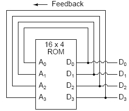
A crude Finite State Machine
The above circuit illustrates the basic idea: the data stored at each address becomes the
next storage location that the ROM gets addressed to. The result is a specific sequence of
binary numbers (following the sequence programmed into the ROM) at the output, over time.
To avoid signal timing problems, though, we need to connect the data outputs back to the
address inputs through a 4-bit D-type flip-flop, so that the sequence takes place step by step to
the beat of a controlled clock pulse:
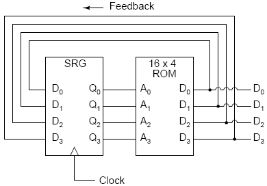
An improved Finite State Machine
An analogy for the workings of such a device might be an array of post-office boxes, each one
with an identifying number on the door (the address), and each one containing a piece of paper
with the address of another P.O. box written on it (the data). A person, opening the first P.O.
box, would find in it the address of the next P.O. box to open. By storing a particular pattern
of addresses in the P.O. boxes, we can dictate the sequence in which each box gets opened, and
therefore the sequence of which paper gets read.
Having 16 addressable memory locations in the ROM, this Finite State Machine would have
16 different stable .states. in which it could latch. In each of those states, the identity of the
next state would be programmed in to the ROM, awaiting the signal of the next clock pulse
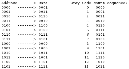
to be fed back to the ROM as an address. One useful application of such an FSM would be to
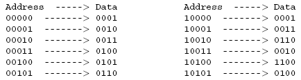
generate an arbitrary count sequence, such as Gray Code:
![]()
Try to follow the Gray Code count sequence as the FSM would do it: starting at 0000, follow the data stored at that address (0001) to the next address, and so on (0011), and so on (0010), and so on (0110), etc. The result, for the program table shown, is that the sequence of addressing jumps around from address to address in what looks like a haphazard fashion, but when you check each address that is accessed, you will find that it follows the correct order for 4-bit Gray code. When the FSM arrives at its last programmed state (address 1000), the data stored there is 0000, which starts the whole sequence over again at address 0000 in step with
the next clock pulse.
We could expand on the capabilities of the above circuit by using a ROM with more address
lines, and adding more programming data:
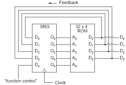
Now, just like the look-up table adder circuit that we turned into an Arithmetic Logic Unit
(+, -, x, / functions) by utilizing more address lines as .function control. inputs, this FSM
counter can be used to generate more than one count sequence, a different sequence programmed
for the four feedback bits (A0 through A3) for each of the two function control line input combinations (A4 = 0 or 1).
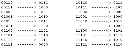
Here, the D0 through D3 data outputs are used exclusively for feedback to the A0 through
A3 address lines. Date output lines D4 through D7 can be programmed to output something
other than the FSM's “state” value. Being that four data output bits are being fed back to four
address bits, this is still a 16-state device. However, having the output data come from other
data output lines gives the programmer more freedom to configure functions than before. In
other words, this device can do far more than just count! The programmed output of this FSM
is dependent not only upon the state of the feedback address lines (A0 through A3), but also
the states of the input lines (A4 through A7). The D-type flip/flop's clock signal input does
not have to come from a pulse generator, either. To make things more interesting, the _ip/_op
could be wired up to clock on some external event, so that the FSM goes to the next state only
when an input signal tells it to.
Now we have a device that better fulfills the meaning of the word .programmable.. The data
written to the ROM is a program in the truest sense: the outputs follow a pre-established order
based on the inputs to the device and which “step” the device is on in its sequence. This is very
close to the operating design of the Turing Machine, a theoretical computing device invented by
Alan Turing, mathematically proven to be able to solve any known arithmetic problem, given
enough memory capacity.
"Distributed software is often structured in terms of clients and services. Each service comprises one or more servers and exports operations that clients invoke by making requests. Although using a single, centralized, server is the simplest way to implement a service, the resulting service can only be as fault tolerant as the processor executing that server. If this level of fault tolerance is unacceptable, then multiple servers that fail independently must be used. Usually, replicas of a single server are executed on separate processors of a distributed system, and protocols are used to coordinate client interactions with these replicas. The physical and electrical isolation of processors in a distributed system ensures that server failures are independent, as required.
"The state machine approach is a general method for implementing a fault-tolerant service by replicating servers and coordinating client interactions with server replicas. The approach also provides a framework for understanding and designing replication management protocols. Many protocols that involve replication of data or software - be it for masking failures or simply to facilitate cooperation without centralized control - can be derived using the state machine approach. Although few of these protocols actually were obtained in this manner, viewing them in terms of state machines helps in understanding how and why they work."
The finite state machine is a formal way to describe an algorithm.
Теория автоматов имеет широкие возможности применения:
Проектирование систем логического управления;
Обработка текстов и построение компиляторов;
Спецификация и верификация систем взаимодействующих процессов;
Языки описания документов и объектно-ориентированных программ;
Оптимизация логических программ др.
A finite state machine is defined by
a set of inputs
a set of states
a set of outputs
a set of maps from states and inputs into states and outputs {state, input} {state, output}
an initial state. As an example, let us describe the sequence of events which takes place when you answer the telephone. For this example, we will assume that you do not have an answering machine or services such as call waiting.
We begin the process by waiting for the telephone to ring; during this time, we are in a wait state, which we will designate W.
When the phone rings, you pick up the handset and change to the answer state (designated A).
At this point, one of four things may happen:
- the person making the call asks for you;
- the person making the call asks for someone who is currently at home;
- the person making the call asks for someone who is currently not at home;
- it is a wrong number.
If the call is for you, you say hello and change to the talking state (designated T).
If the call is for someone who is currently at home, you tell the person making the call to wait and move to a state where you are getting the person they desire (designated G).
If the call is for someone who is currently not at home, you tell the caller and change to the state where you are taking a message (designated M).
If it is a wrong number, you tell the caller and move to the state where the call is finishing (designated F).
Once in the talking state, whenever the caller talks you reply and stay in the talking state.
If however, the caller says goodbye, you say goodbye and move to the finish state.
If you were in the state where you were getting someone else to come to the phone, when they arrive they say hello and enter the talking state.
If you are taking a message and the caller says goodbye, you say goodbye and move to the finish state.
Once in the finish state, when the caller hangs up, you hang up the handset and change to the wait state. We represent this sequence as a finite state machine as follows:
the set of inputs is {ring, call is for you, call is for someone currently at home, call is for someone not currently at home, call is a wrong number, person you are getting comes to the phone, caller talks, caller says goodbye, caller hangs up}
the set of states is {waiting for a call (W), answering the phone (A), talking (T), getting someone else to come to the phone (G), taking a message (M), finishing the call (F)}
the set of outputs is {picking up the phone, saying hello, telling the caller to wait, telling the caller that the person they requested is not at home, telling the caller that they have dialed a wrong number, replying to the caller, saying goodbye, hanging up the handset}
the set of maps was described in the sequence above
the initial state is the wait state (W)
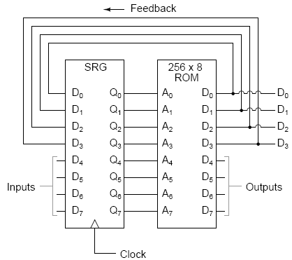
We can represent this finite state machine as a labeled directed graph where
the states are represented by vertices
the arcs represent state transitions and are labeled with inputs and outputs (here we have omitted the outputs for reasons of clarity):
Fig.13. Finite state machine representation using a directed graph.
When a finite state machine is represented as a directed graph, the matrix representation is called a state table. Here, rows are labeled by states, the columns are labeled by inputs, and the matrix elements consist of the outputs and the next state to move to:
. |
ring |
for you |
at home |
not at home |
wrong number |
comes to phone |
caller talks |
good-bye |
hang-up |
wait (W) |
pick up, A |
. |
. |
. |
. |
. |
. |
. |
. |
answer (A) |
. |
hello, T |
wait, G |
tell them, M |
tell them, F |
. |
. |
. |
. |
talk (T) |
. |
. |
. |
. |
. |
. |
reply, T |
goodbye, F |
. |
get person (G) |
. |
. |
. |
. |
. |
hello, T |
. |
. |
. |
take msg (M) |
. |
. |
. |
. |
. |
. |
. |
goodbye, F |
. |
finished (F) |
. |
. |
. |
. |
. |
. |
. |
. |
hang up, W |
The finite state machine is a formal way to describe an algorithm; in this example, we have given an algorithm for answering the telephone. When the algorithm is applied to an actual series of inputs, we can construct a table which illustrates the sequence of states entered by the machine as it processes the algorithm. For instance, in the case of a wrong number, the sequence of inputs and states is
input |
output |
next state |
ring |
pick up phone |
A |
wrong number |
tell them |
F |
hang-up |
hang up phone |
W |
while in the case where the caller talks to someone other than the person who answers the sequence is
input |
output |
next state |
ring |
pick up phone |
A |
at home |
ask them to wait |
G |
comes to phone |
say hello |
T |
talks |
reply |
T |
talks |
reply |
T |
talks |
reply |
T |
says goodbye |
say goodbye |
F |
hangs up |
hang up phone |
W |
These tables are often summarized in the form of a sequence of states, ie.:
A, F, W
and
A, G, T, T, T, T, F, W
respectively.
They can also be summarized as a sequence of outputs:
pick up phone, tell them (it's a wrong number), hang up phone
and
pick up phone, ask them to wait, say hello, reply, reply, reply, say goodbye, hang up phone
respectively.
When you learn about networking, you will find that the finite state machine is the common language for describing networking protocols, especially in TCP/IP, where our example in this section is very similar to the finite state machine which describes the establishment of a TCP connection.
The section concludes our discussion of graph theory. In the next chapter, we begin the quantitative measurement of computer capacities and performance with a discussion of units of measurement.
Обобщенная структурная схема автомата.
На стадии абстрактного синтеза обычно пользуются представлением автомата в виде одного блока, имеющего один вход и один выход. На стадии структурного синтеза автомат изображают в виде обобщенной структурной схемы, приведенной на рис. 9.1, имеющей n входных и m выходных каналов, по которым в подавляющем большинстве случаев передаются двоичные сигналы x1, x2, ..., xn и z1, z2, ..., zm. Переменные x1, x2, ..., xn называют входными переменными, а z1, z2, ...,zm -выходными переменными или функциями выходов автомата.
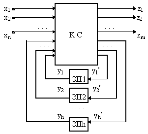
Fig.13. Обобщенная структурная схема автомата
Рассматриваемая схема состоит из двух частей: комбинационной схемы (КС) и набора элементов памяти (ЭП). Переменные y1, y2, ..., yh, соответствующие выходным сигналам элементов памяти, называют внутренними переменными автомата. Переменные y1', y2', ... , yh' используются в схеме для обозначения входных сигналов, изменяющих состояние элементов памяти, и называют функциями возбуждения. В качестве элементов памяти на практике чаще всего используют элементарные автоматы. В приведенной схеме наборы значений входных переменных x1, x2, ..., xn соответствуют буквам входного алфавита Р абстрактного автомата, наборы выходных переменных z1, z2, ..., zm - буквам выходного алфавита W, y1, y2, ..., yh - состояниям абстрактного автомата.