

10. Holding work in a chuck
Short parts are usually held in a chuck. This method of holding work is of great importance since it is widely used with lathes. A chuck is a rotating vice which may be attached to the nose of the lathe spindle. There are three important varieties of lathe chucks, such as independent jaw chucks, concentric or self-centering chucks or contracting chucks.
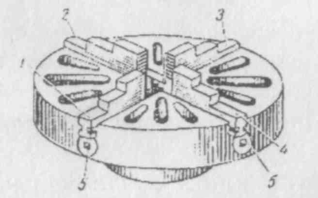
Fig.28. Independent Four-Jaw Chuck 1,2,3,4 -jaws; 5 – screw
Fig. 28 shows an independent four-jaw chuck belonging to the group of simple chucks. The chuck has four jaws 1, 2, 3, 4 carried in radial slots in the chuck body. Each jaw of the chuck can he adjusted independently by means of its own screw 5. It others the possibility to fasten works of both cylindrical and non-cylindrical shape in such chucks. The body of the chuck is provided with a screwed hole to fit the spindle nose of the lathe. Fig. 29, a shows a concentric chuck.
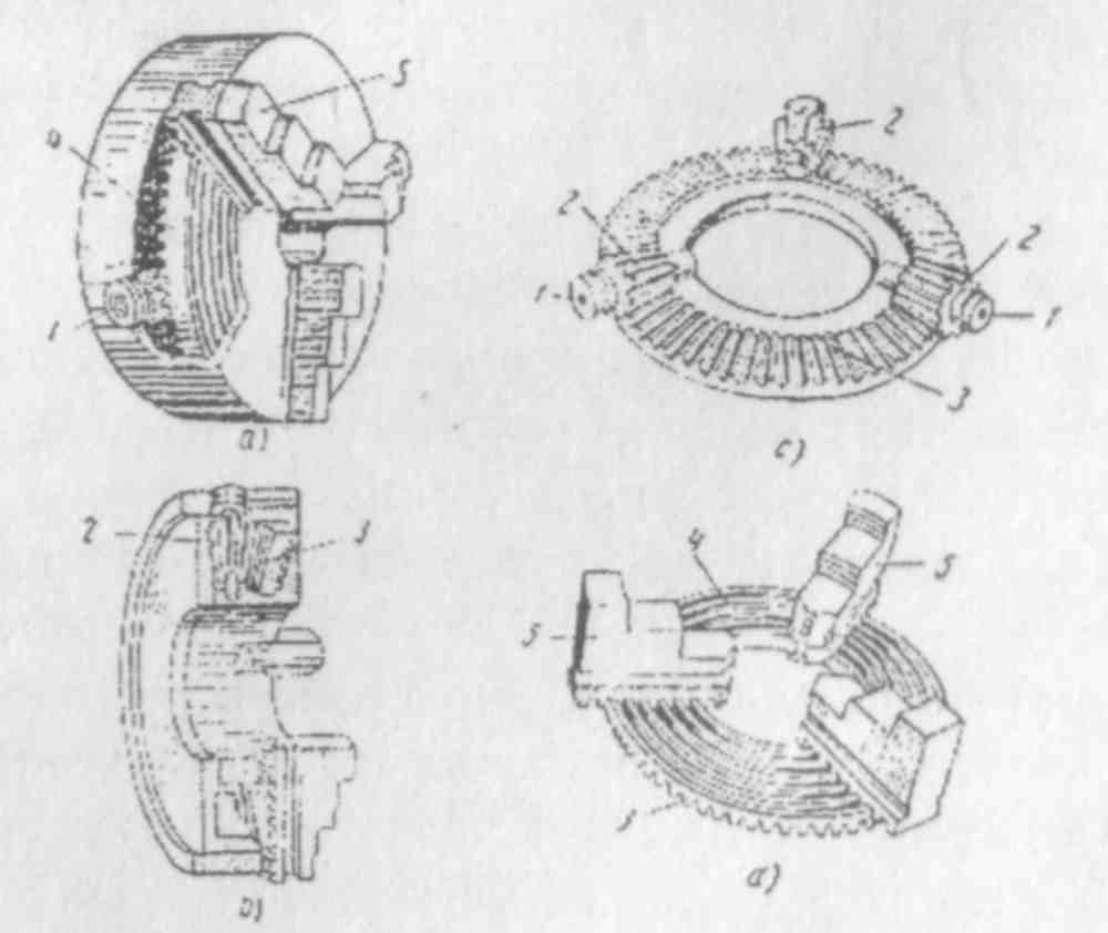
Fig. 29. Concentric Chuck:
1 - chuck key; 2 - bevel gears; 8 - large bevel gear; 4 -
multi-turn spiral groove; 5 -jaws
The concentric chuck usually has three jaws which can be moved in and out1 together by means of a chuck key; which is inserted into the opening of one of the three bevel gears (Fig.29, c) meshed with a large bevel gear (Fig. 29, c). A multiturn spiral groove (Fig. 29, d) is cut on the flat reverse side of the large bevel gear. The bottom projections of the jaws are inserted into the separate turns of the groove. When one of the bevel gears is turned by means of the chuck key its motion is transmitted to the large, bevel gear. The rotation of that large bevel gear causes simultaneous and uniform motion of all the three jaws along the slots of the chuck by means of the spiral groove. When the gear with the spiral groove is rotated in that or another direction2 the jaws are either approached to or removed from the centre thus clamping or unclamping the work. The concentric or self-centering chuck is very convenient in operation as all its jaws are moved simultaneously. Consequently a work of cylindrical shape is clamped exactly along the spindle axis. This centering is done automatically, therefore such chucks are called "self-centering".
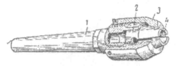
Fig. 30. Collet Chuck or Contracting Chuck:
1 - shank; 2 - collet; 3 - nut; 4 - collet opening
The jaws of the chuck are made of hardened and tempered steel to prevent their wear. The chucks are characterized by strong, all-steel construction3, and are designed to be mounted directly on the spindles of machines without any intermediate plate or adapter, thus ensuring utmost accuracy and rigidity. Fig. 30 shows a collet or a contracting chuck. Such chucks are applied for rapid fastening short works of small diameter. The tapered shank of the chuck is inserted into the taper hole of the headstock spindle. A collet with a cone is placed inside the groove of the chuck. The work to be treated is set into the hole of the collet. When the nut is screwed on the body of the chuck the collet is contracted and the work gets clamped. Magnetic chucks are adapted to work which is difficult to hold in chuck jaws, either on account of its shape or because the pressure of the jaws may distort the work. The magnetic chucks have no jaws, as the work is held by magnetic force instead of by mechanical means. Some workpieces are so shaped that they cannot be held in a chuck, and work of this kind is often clamped to a. faceplate. Most lathes are equipped with two faceplates: one small plate is used for driving workpieces turned between centres, and a large one is used to hold heavy or irregularly shaped pieces.
For finishing the external diameter of work which is already bored axially a mandrel is used. A mandrel is a bar with centre holes at each end. The mandrel is mounted between centres and enables the outside of a workpiece to be turned concentric with the inside and in general such work would have the whole finished first and the outside finished on a mandrel subsequently. The advantage of mounting work on a mandrel is that of being able to reverse the work on the centres so that the whole of the work exterior can be operated on by cutting tools.
1. to move in and out - вдвигать и выдвигать
2. in that or another direction - в том или ином направлении
3. all-steel construction - цельнолитая конструкция
Exercises
I. Use the following words and phrases in sentences of your own:
chuck, rotating vice, lathe spindle, independent jaw chuck, contracting chuck, chuck body, chuck key, to project, to reverse, motion, to transmit, to mesh, bevel gear, faceplate, mandrel
II. Answer the following questions:
1. Where are usually short parts held when being turned in a lathe? 2. What is a chuck? 3. V/hat types of chucks do you know'? 4. What purposes are chucks used for? 5. What kind of work are magnetic chucks adapted to? 6. How is the work held in a magnetic chuck? 7. How many faceplates are most lathes equipped with? 8. What kind of work is a mandrel used for? 9. What is. the advantage of mounting work on a mandrel?
III. Supply English equivalents for the following words and word combinations:
self-centering chuck, independent jaw chuck, collet chuck, radial slots, groove, spindle nose
IV Find in the text synonyms of the following words:
collet chuck, comfortably, with the help of, slot, to revolve
V. Give derivatives from the following words and translate them into Russian:
to divide, dependent, possible, cylinder, to open, to transmit, to ensure
VI. Read and translate the following text without using a dictionary and analyze the ing-forms and ed-forms:
The standard chucks generally furnished are mechanically operated by an automatic mechanism which gives the operator total freedom of both hands for handling the work. While the machine is running to cycle time1 he simply places the work in the chuck which is held there by the work locator2 then he releases the safety foot treadle3. There are no chucking levers or valves and gauges that require his attention and time. Standard chucks can be furnished with either two or three simple jaws and with the jaws contracting or expanding. Chucking pressures are the same at all positions and the pressures are adjustable for different types of work. All standard chucks are constructed entirely of steel having a solid steel body, and all the moving parts are made of hardened alloy steel to withstand wear.
1. cycle time - цикл хронометрирования
2. work locator - фиксатор
3. safety foot treadle – предохранительная ножная педаль
VII. Giving answers to the following questions describe the s independent four-jaw chuck shown in Fig. 28 and its a principle of operation:
1. What kind of chuck is shown in Fig. 28? 2. What group of chucks does the independent four-jaw chuck belong to? 3. How many jaws has the chuck? 4. Where are the four jaws of the chuck situated? 5. How can each jaw of the chuck be adjusted? 6. What possibility is offered by the independent adjustment of jaws? 7. What is the body of the chuck provided with?
VIII. Using the following words and word combinations describe the construction and principle of operation of the concentric chuck shown in Fig. 29:
a concentric chuck, to have three jaws, to move in and out, a chuck key, to be inserted, the opening, one of three bevel gears, to be meshed with a large bevel gear, on the flat reverse side, the large bevel gear, a multiturn spiral groove, to be cut, the motion of one of the bevel gears, to be transmitted, by means of the chuck, key, to move simultaneously and uniformly, the slots of the body, due to the spiral groove, rotating in that or another direction, the gear with the spiral grooves, to cause, approaching or removing, the jaws of the chuck, from the centre, due to this, the work, to be clamped or unclamped, the advantage, the concentric or self-centering chuck, in moving all jaws simultaneously
X. Describe the construction and principle of operation of the contracting chuck shown in Fig. 30.