

Chapter 5: Object Interaction
End of a Lifeline
Rose 2001A and 2002 give you greater control over the display of an object's lifeline on a Sequence diagram. Specifically, they give you the ability to position an object at the point at which it is instantiated and the ability to add a destruction marker to indicate when the object is destroyed.
Let's first look at the beginning of the lifeline. As a scenario progresses, objects will be created and destroyed. In Rose 2001A and 2002, you can move an object vertically to indicate where it is created:
You can also indicate when an object is removed from memory. This can be especially helpful in optimizing a design, because it gives you a quick way to see when memory is "cleaned up" in a specific scenario.
The destruction marker is used to indicate the end of a lifeline. It appears as an "X" on the lifeline itself, and the lifeline will not extend beyond it:
To add a lifeline:
1.
Select the Destruction Marker icon from the toolbar.
2.
Click on the object's lifeline, at the point where it is removed from memory.
Working with Scripts
In Rose, notes are typically used to add a comment to an object. Scripts, on the other hand, are usually used to
189
Chapter 5: Object Interaction
add a comment to a message. Scripts are only used on Sequence diagrams. They are usually placed on the left side of the diagram, opposite the message they refer to.
You can use a script to clarify the meaning of a message. You may have a message that reads "Validate User." In the script, you can expand on the meaning: "Validate the ID to be sure that the user exists and that the password is correct."
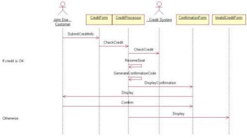
You can also use scripts to enter some conditional logic in your diagram. Figure 5.19 illustrates some sample scripts in a Sequence diagram.
Figure 5.19: Using scripts in a Sequence diagram
In general, try to avoid putting so much conditional logic on the diagram that the diagram loses its simplicity. By the time you add the details of a nested If statement inside a nested If statement inside a nested If statement, your diagram will probably be cluttered. On the other hand, there are times when you need to show a little bit of conditional logic. Just balance the two extremes. As long as the diagram is easily readable and understandable, you should be fine. If the conditional logic gets too complicated, just create additional Sequence diagrams: one to deal with the if part, one to deal with the else part, and so on.
Besides If statements, you can use scripts to show loops and other pseudocode on your diagram. Scripts won't generate any code, but they will let the developers know how the logic is intended to flow.
To add a script to a Sequence diagram:
1.
Select the Text Box toolbar button.
2.
Click in the location on the diagram where you want the script to reside. Usually this is near the left edge of the diagram.
3.
With the text box selected, type the text of the script.
4.
190
Chapter 5: Object Interaction
Select the text box. Press and hold down Shift and select the message.
5.
Select Edit → Attach Script.
6.
Now, when you move the message up or down in the diagram, the script will move along with it.
To detach a script from a message:
1.
Select the script.
2.
Select Edit → Detach Script.
Switching Between Sequence and Collaboration Diagrams
Typically, you create either a Sequence or a Collaboration diagram for a particular scenario. Without a modeling tool like Rose, it can be too time−consuming to create both, especially because both show you the same information.
In Rose, however, it's very easy to create a Sequence diagram from a Collaboration diagram, or to create a Collaboration diagram from a Sequence diagram. Once you have both a Sequence and a Collaboration diagram for a scenario, it's very easy to switch between the two.
To create a Collaboration diagram from a Sequence diagram:
1.
Open the Sequence diagram.
2.
Select Browse → Create Collaboration diagram, or press F5.
3.
Rose will create a Collaboration diagram with the same name as the open Sequence diagram.
To create a Sequence diagram from a Collaboration diagram:
1.
Open the Collaboration diagram.
2.
Select Browse → Create Sequence diagram, or press F5.
3.
Rose will create a Sequence diagram with the same name as the open Collaboration diagram.
191
Chapter 5: Object Interaction
To switch between Sequence and Collaboration diagrams:
1.
Open the Sequence or Collaboration diagram.
2.
Select Browse → Go to (Sequence or Collaboration) Diagram, or press F5.
3.
Rose will look for a Sequence or Collaboration diagram with the same name as the open diagram.
Two−Pass Approach to Interaction Diagrams
Frequently, people use a two−pass approach to creating Interaction diagrams. On the first pass, they focus on higher−level information that the customers will be concerned with. Messages aren't mapped to operations yet, and objects may not be mapped to classes. These diagrams let just the analysts, customers, and anyone else interested in the business flow see how the logic will flow in the system.
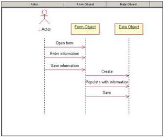
The first pass of a Sequence diagram might look like Figure 5.20.
Figure 5.20: First−pass Sequence diagram
In the second pass, once the customers have agreed to the flow from the first−pass diagram, the team adds more of the detail. The diagram at this point may lose its usefulness to the customer, but will become very useful to the developers, testers, and other members of the project team.
To begin, some additional objects may be added to the diagram. Each Interaction diagram may have a control object, which is responsible for controlling the sequencing through a scenario. All of the Interaction diagrams for a use case may share the same control object, so you have one control object that handles all of the sequencing information for the use case.
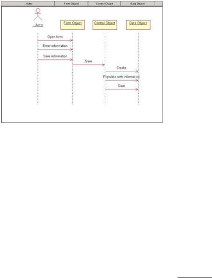
If you add a control object, your Sequence diagram will typically look something like Figure 5.21.
192
Chapter 5: Object Interaction
Figure 5.21: Sequence diagram with control object
Notice that the control object doesn't carry out any business processing; it just sends off messages to the other objects. The control object is responsible for coordinating the efforts of the other objects and delegating responsibility. For this reason, control objects are sometimes called manager objects.
The benefit of using a control object is separating the business logic from the sequencing logic. If the sequencing needs to change, only the control object will be affected.
You may also want to add some objects to handle things like security, error handling, or database connectivity. Many of these objects are generic enough to be built once and reused in many applications. Let's take a look at the database issues, for example.
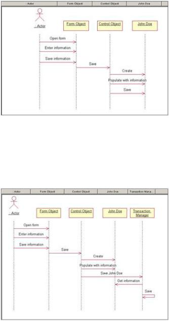
There are two commonly used options when trying to save information to a database or retrieve information from a database. Say we're trying to save a new employee, John Doe, to the database. The John Doe object can either know about the database, in which case it saves itself to the database, or it can be completely separated from the database logic, in which case another object has to handle saving John to the database. Let's start with John knowing about the database, as shown in Figure 5.22.
In this situation, there is no separation of application logic and database logic. The John Doe object takes care of application logic, such as hiring and firing John Doe, as well as database logic, including saving John to the database and retrieving him later. Should the database need to change, the change will ripple through more of the application this way, because many objects will contain some database logic. On the other hand, this approach can be easy to model and implement.
193
Chapter 5: Object Interaction
Figure 5.22: Application logic integrated with database logic
Another option is to separate the application logic from the database logic. In this situation, you will need to create another object to deal with the database logic. We'll call this new object Transaction Manager. The John Doe object will still hold the business logic; it will know how to hire or fire John, or how to give him a raise. The Transaction Manager object will know how to retrieve John from the database or save him to the database. The Sequence diagram might look something like Figure 5.23.
Figure 5.23: Application logic separated from database logic
The advantage of this approach is that now it's easier to reuse the John Doe object in another application with a different database, or with no database at all. It also helps minimize the impact of a requirement change. Database changes won't affect the application logic, and application changes won't affect the database logic. The disadvantage here can be that you'll need a little more time to model and implement this solution.
These are two of the more common approaches, although there are some other approaches you can take when dealing with database issues. Whichever decision you make, be sure to keep the approach consistent across Interaction diagrams.
Aside from database issues, you may add objects now for things like error handling, security, or interprocess communication. These details won't interest the customer, but will be critical for the developers.
194