

Chapter 5: Object Interaction
Set the Focus of Control check box to on or off, as shown in Figure 5.11.
Figure 5.11: Focus of Control check box
Adding Messages to a Collaboration Diagram
Before you can add messages to a Collaboration diagram, you have to establish a path of communication between two objects. This path is called a link, and is created using the Object Link toolbar button. Once the link has been added, you can add messages between the objects.
To add a message to a Collaboration diagram:
1.
Select the Object Link toolbar button.
2.
Drag from one object to the other to create the link.
3.
Select the Link Message or Reverse Link Message toolbar button.
4.
Click the link between the two objects. Rose will draw the message arrow, as shown in Figure 5.12.
Figure 5.12: Adding a message to a Collaboration diagram
5.
With the new message selected, type the text of the message.
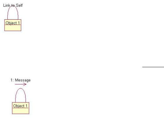
To add a reflexive message to a Collaboration diagram:
1. |
179 |
Chapter 5: Object Interaction
Select the Link to Self toolbar button.
2.
Click the object sending and receiving the message. Rose will draw a reflexive link on the object. It will appear above the object and look like a half−circle.
3.
Select the Link Message toolbar button.
4.
Click the object's reflexive link. Rose will add the message arrow, as shown in Figure 5.13.
Figure 5.13: Adding a reflexive message to a Collaboration diagram
5.
With the new message still selected, enter the text of the message.
Note If you are adding more than one reflexive message to an object in a Collaboration diagram, skip steps one and two for each additional message.
Deleting Messages from a Collaboration Diagram
As with Sequence diagrams, you can delete messages from a Collaboration diagram. When you delete a message, Rose will automatically renumber the remaining messages.
To delete a message from a Collaboration diagram:
1.
Select the message to delete.
2.
Select Edit → Delete From Model, or press Ctrl+D.
180

Chapter 5: Object Interaction
Message Numbering in a Collaboration Diagram
With a Sequence diagram, you know that you read the diagram from top to bottom, so message numbering isn't necessary. A Collaboration diagram, however, loses its sequencing information if you remove the message numbering.
You do have the option in Rose of turning off message numbering in a Collaboration diagram. To turn message numbering on or off:
1.
Select Tools → Options.
2.
Select the Diagram tab.
3.
Set the Collaboration and Sequence Numbering check box to on or off.
Adding Data Flows to a Collaboration Diagram
We mentioned earlier that one of the differences between a Sequence and a Collaboration diagram is the use of the focus of control. The other difference is in the use of data flow. Collaboration diagrams show data flows; Sequence diagrams do not.
Data flows are used to show the information that is returned when one object sends a message to another. In general, you don't add data flows to every message on a Collaboration diagram, because it can clutter the diagram with information that's not really valuable. If a message just returns a comment such as "OK, the message was received and everything worked fine" or "Oops! There was an error in running the requested function," it's probably not worth showing on the diagram. But if a message returns a structure, say a list of employees working for the company, this may be significant enough to show on a diagram.
When you eventually map each message to an operation of a class, the information in the data flows will be added to the operation's details. As a general rule, don't waste too much time worrying about data flows now. Add them to the diagram if you think they're significant enough to help the developers. If not, leave them out.
To add a data flow to a Collaboration diagram:
1.
Select the Data Token or Reverse Data Token toolbar button.
2.
Click on the message that will be returning data. Rose will automatically add the data flow arrow to the diagram, as shown in Figure 5.14.
Figure 5.14: Adding a data flow to a Collaboration diagram
3.
181
Chapter 5: Object Interaction
With the new data flow still selected, type in the data that will be returned.
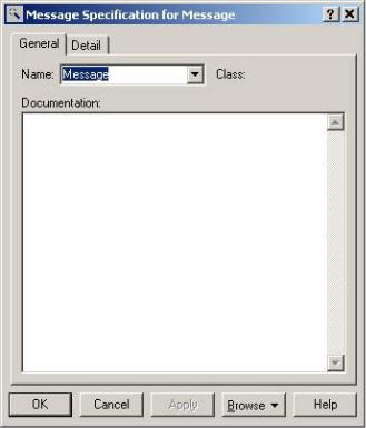
Setting Message Specifications
In Rose, you can set a number of different options to add detail to each message. As with use cases and actors, you can add names and documentation to messages. You can also set synchronization and frequency options. In this section, we'll discuss each of the options you can set for a message.
To open the message specifications:
Double−click the message on the diagram. The message specification window will appear, as shown in Figure 5.15.
Figure 5.15: Message specification window
OR
1.
Select the message on the diagram.
2.
Select Browse → Specification, or press Ctrl+B.
Naming a Message
In the message specification window, you can name the message or change the name, and add documentation. Each message should have a name that indicates the purpose of the message. Later, as you map each of the messages to operations, the message name will be replaced with the operation name.
182