

- •Table of Contents
- •Mastering UML with Rational Rose 2002
- •Chapter 1: Introduction to UML
- •Encapsulation
- •Inheritance
- •Polymorphism
- •What Is Visual Modeling?
- •Systems of Graphical Notation
- •Booch Notation
- •Object Management Technology (OMT)
- •Unified Modeling Language (UML)
- •Understanding UML Diagrams
- •Business Use Case Diagrams
- •Use Case Diagrams
- •Activity Diagrams
- •Sequence Diagrams
- •Collaboration Diagrams
- •Class Diagrams
- •Statechart Diagrams
- •Component Diagrams
- •Deployment Diagrams
- •Visual Modeling and the Software Development Process
- •Inception
- •Elaboration
- •Construction
- •Transition
- •Summary
- •Chapter 2: A Tour of Rose
- •What Is Rose?
- •Getting Around in Rose
- •Parts of the Screen
- •Exploring Four Views in a Rose Model
- •Use Case View
- •Logical View
- •Component View
- •Deployment View
- •Working with Rose
- •Creating Models
- •Saving Models
- •Exporting and Importing Models
- •Publishing Models to the Web
- •Working with Controlled Units
- •Using the Model Integrator
- •Working with Notes
- •Working with Packages
- •Adding Files and URLs to Rose Model Elements
- •Adding and Deleting Diagrams
- •Setting Global Options
- •Working with Fonts
- •Working with Colors
- •Summary
- •Chapter 3: Business Modeling
- •Introduction to Business Modeling
- •Why Model the Business?
- •Do I Need to Do Business Modeling?
- •Business Modeling in an Iterative Process
- •Business Actors
- •Business Workers
- •Business Use Cases
- •Business Use Case Diagrams
- •Activity Diagrams
- •Business Entities
- •Organization Unit
- •Where Do I Start?
- •Identifying the Business Actors
- •Identifying the Business Workers
- •Identifying the Business Use Cases
- •Showing the Interactions
- •Documenting the Details
- •Creating Business Use Case Diagrams
- •Deleting Business Use Case Diagrams
- •The Use Case Diagram Toolbar
- •Adding Business Use Cases
- •Business Use Case Specifications
- •Assigning a Priority to a Business Use Case
- •Viewing Diagrams for a Business Use Case
- •Viewing Relationships for a Business Use Case
- •Working with Business Actors
- •Adding Business Actors
- •Adding Actor Specifications
- •Assigning an Actor Stereotype
- •Setting Business Actor Multiplicity
- •Viewing Relationships for a Business Actor
- •Working with Relationships
- •Association Relationship
- •Generalization Relationship
- •Working with Organization Units
- •Adding Organization Units
- •Deleting Organization Units
- •Activity Diagrams
- •Adding an Activity Diagram
- •Adding Details to an Activity Diagram
- •Summary
- •Chapter 4: Use Cases and Actors
- •Use Case Modeling Concepts
- •Actors
- •Use Cases
- •Traceability
- •Flow of Events
- •Relationships
- •Use Case Diagrams
- •Activity Diagrams
- •Activity
- •Start and End States
- •Objects and Object Flows
- •Transitions
- •Synchronization
- •Working with Use Cases in Rational Rose
- •The Use Case Diagram Toolbar
- •Creating Use Case Diagrams
- •Deleting Use Case Diagrams
- •Adding Use Cases
- •Deleting Use Cases
- •Use Case Specifications
- •Naming a Use Case
- •Viewing Participants of a Use Case
- •Assigning a Use Case Stereotype
- •Assigning a Priority to a Use Case
- •Creating an Abstract Use Case
- •Viewing Diagrams for a Use Case
- •Viewing Relationships for a Use Case
- •Working with Actors
- •Adding Actors
- •Deleting Actors
- •Actor Specifications
- •Naming Actors
- •Assigning an Actor Stereotype
- •Setting Actor Multiplicity
- •Creating an Abstract Actor
- •Viewing Relationships for an Actor
- •Viewing an Actor's Instances
- •Working with Relationships
- •Association Relationship
- •Includes Relationship
- •Extends Relationship
- •Generalization Relationship
- •Working with Activity Diagrams
- •The Activity Diagram Toolbar
- •Creating Activity Diagrams
- •Deleting Activity Diagrams
- •Exercise
- •Problem Statement
- •Create a Use Case Diagram
- •Summary
- •Chapter 5: Object Interaction
- •Interaction Diagrams
- •What Is an Object?
- •What Is a Class?
- •Where Do I Start?
- •Finding Objects
- •Finding the Actor
- •Using Interaction Diagrams
- •Sequence Diagrams
- •The Sequence Diagram Toolbar
- •Collaboration Diagrams
- •The Collaboration Diagram Toolbar
- •Working with Actors on an Interaction Diagram
- •Working with Objects
- •Adding Objects to an Interaction Diagram
- •Deleting Objects from an Interaction Diagram
- •Setting Object Specifications
- •Naming an Object
- •Mapping an Object to a Class
- •Setting Object Persistence
- •Using Multiple Instances of an Object
- •Working with Messages
- •Adding Messages to an Interaction Diagram
- •Adding Messages to a Sequence Diagram
- •Deleting Messages from a Sequence Diagram
- •Reordering Messages in a Sequence Diagram
- •Message Numbering in a Sequence Diagram
- •Viewing the Focus of Control in a Sequence Diagram
- •Adding Messages to a Collaboration Diagram
- •Deleting Messages from a Collaboration Diagram
- •Message Numbering in a Collaboration Diagram
- •Adding Data Flows to a Collaboration Diagram
- •Setting Message Specifications
- •Naming a Message
- •Mapping a Message to an Operation
- •Setting Message Synchronization Options
- •Setting Message Frequency
- •End of a Lifeline
- •Working with Scripts
- •Switching Between Sequence and Collaboration Diagrams
- •Exercise
- •Problem Statement
- •Create Interaction Diagrams
- •Summary
- •Chapter 6: Classes and Packages
- •Logical View of a Rose Model
- •Class Diagrams
- •What Is a Class?
- •Finding Classes
- •Creating Class Diagrams
- •Deleting Class Diagrams
- •Organizing Items on a Class Diagram
- •Using the Class Diagram Toolbar
- •Working with Classes
- •Adding Classes
- •Class Stereotypes
- •Analysis Stereotypes
- •Class Types
- •Interfaces
- •Web Modeling Stereotypes
- •Other Language Stereotypes
- •Class Specifications
- •Naming a Class
- •Setting Class Visibility
- •Setting Class Multiplicity
- •Setting Storage Requirements for a Class
- •Setting Class Persistence
- •Setting Class Concurrency
- •Creating an Abstract Class
- •Viewing Class Attributes
- •Viewing Class Operations
- •Viewing Class Relationships
- •Using Nested Classes
- •Viewing the Interaction Diagrams That Contain a Class
- •Setting Java Class Specifications
- •Setting CORBA Class Specifications
- •Working with Packages
- •Adding Packages
- •Deleting Packages
- •Exercise
- •Problem Statement
- •Creating a Class Diagram
- •Summary
- •Chapter 7: Attributes and Operations
- •Working with Attributes
- •Finding Attributes
- •Adding Attributes
- •Deleting Attributes
- •Setting Attribute Specifications
- •Setting the Attribute Containment
- •Making an Attribute Static
- •Specifying a Derived Attribute
- •Working with Operations
- •Finding Operations
- •Adding Operations
- •Deleting Operations
- •Setting Operation Specifications
- •Adding Arguments to an Operation
- •Specifying the Operation Protocol
- •Specifying the Operation Qualifications
- •Specifying the Operation Exceptions
- •Specifying the Operation Size
- •Specifying the Operation Time
- •Specifying the Operation Concurrency
- •Specifying the Operation Preconditions
- •Specifying the Operation Postconditions
- •Specifying the Operation Semantics
- •Displaying Attributes and Operations on Class Diagrams
- •Showing Attributes
- •Showing Operations
- •Showing Visibility
- •Showing Stereotypes
- •Mapping Operations to Messages
- •Mapping an Operation to a Message on an Interaction Diagram
- •Exercise
- •Problem Statement
- •Add Attributes and Operations
- •Summary
- •Chapter 8: Relationships
- •Relationships
- •Types of Relationships
- •Finding Relationships
- •Associations
- •Using Web Association Stereotypes
- •Creating Associations
- •Deleting Associations
- •Dependencies
- •Creating Dependencies
- •Deleting Dependencies
- •Package Dependencies
- •Creating Package Dependencies
- •Deleting Package Dependencies
- •Aggregations
- •Creating Aggregations
- •Deleting Aggregations
- •Generalizations
- •Creating Generalizations
- •Deleting Generalizations
- •Working with Relationships
- •Setting Multiplicity
- •Using Relationship Names
- •Using Stereotypes
- •Using Roles
- •Setting Export Control
- •Using Static Relationships
- •Using Friend Relationships
- •Setting Containment
- •Using Qualifiers
- •Using Link Elements
- •Using Constraints
- •Exercise
- •Problem Statement
- •Adding Relationships
- •Summary
- •Chapter 9: Object Behavior
- •Statechart Diagrams
- •Creating a Statechart Diagram
- •Adding States
- •Adding State Details
- •Adding Transitions
- •Adding Transition Details
- •Adding Special States
- •Using Nested States and State History
- •Exercise
- •Problem Statement
- •Create a Statechart Diagram
- •Summary
- •Chapter 10: Component View
- •What Is a Component?
- •Types of Components
- •Component Diagrams
- •Creating Component Diagrams
- •Adding Components
- •Adding Component Details
- •Adding Component Dependencies
- •Exercise
- •Problem Statement
- •Summary
- •Chapter 11: Deployment View
- •Deployment Diagrams
- •Opening the Deployment Diagram
- •Adding Processors
- •Adding Processor Details
- •Adding Devices
- •Adding Device Details
- •Adding Connections
- •Adding Connection Details
- •Adding Processes
- •Exercise
- •Problem Statement
- •Create Deployment Diagram
- •Summary
- •Chapter 12: Introduction to Code Generation and Reverse Engineering Using Rational Rose
- •Preparing for Code Generation
- •Step One: Check the Model
- •Step Two: Create Components
- •Step Three: Map Classes to Components
- •Step Five: Select a Class, Component, or Package
- •Step Six: Generate Code
- •What Gets Generated?
- •Introduction to Reverse Engineering Using Rational Rose
- •Model Elements Created During Reverse Engineering
- •Summary
- •Chapter 13: ANSI C++ and Visual C++ Code Generation and Reverse Engineering
- •Generating Code in ANSI C++ and Visual C++
- •Converting a C++ Model to an ANSI C++ Model
- •Class Properties
- •Attribute Properties
- •Operation Properties
- •Package (Class Category) Properties
- •Component (Module Specification) Properties
- •Role Properties
- •Generalization Properties
- •Class Model Assistant
- •Component Properties
- •Project Properties
- •Visual C++ and ATL Objects
- •Generated Code
- •Code Generated for Classes
- •Code Generated for Attributes
- •Code Generated for Operations
- •Visual C++ Code Generation
- •Reverse Engineering ANSI C++
- •Reverse Engineering Visual C++
- •Summary
- •Overview
- •Introduction to Rose J
- •Beginning a Java Project
- •Selecting a Java Framework
- •Linking to IBM VisualAge for Java
- •Linking to Microsoft Visual J++
- •Project Properties
- •Class Properties
- •Attribute Properties
- •Operation Properties
- •Module Properties
- •Role Properties
- •Generating Code
- •Generated Code
- •Classes
- •Attributes
- •Operations
- •Bidirectional Associations
- •Unidirectional Associations
- •Associations with a Multiplicity of One to Many
- •Associations with a Multiplicity of Many to Many
- •Reflexive Associations
- •Aggregations
- •Dependency Relationships
- •Generalization Relationships
- •Interfaces
- •Java Beans
- •Support for J2EE
- •EJBs
- •Servlets
- •JAR and WAR Files
- •Automated J2EE Deployment
- •Reverse Engineering
- •Summary
- •Starting a Visual Basic Project
- •Class Properties
- •Attribute Properties
- •Operation Properties
- •Module Specification Properties
- •Role Properties
- •Generalization Properties
- •Generated Code
- •Classes
- •Attributes
- •Operations
- •Bidirectional Associations
- •Unidirectional Associations
- •Associations with a Multiplicity of One to Many
- •Associations with a Multiplicity of Many to Many
- •Reflexive Associations
- •Aggregations
- •Dependency Relationships
- •Generalization Relationships
- •Reverse Engineering
- •Summary
- •Overview
- •Introduction to XML DTD
- •Elements
- •Attributes
- •Entities and Notations
- •Project Properties
- •Class Properties
- •Attribute Properties
- •Role Properties
- •Component Properties
- •Generating Code
- •Generated Code
- •Classes
- •Attributes
- •Reverse Engineering DTD
- •Summary
- •Project Properties
- •Class Properties
- •Attribute Properties
- •Operation Properties
- •Module Properties
- •Association (Role) Properties
- •Dependency Properties
- •Generated Code
- •Classes
- •Attributes
- •Operations
- •Bidirectional Associations
- •Unidirectional Associations
- •Associations with a Multiplicity of One to Many
- •Associations with a Multiplicity of Many to Many
- •Associations with Bounded Multiplicity
- •Reflexive Associations
- •Aggregations
- •Dependency Relationships
- •Generalization Relationships
- •Reverse Engineering CORBA Source Code
- •Summary
- •Chapter 18: Rose Data Modeler
- •Object Models and Data Models
- •Creating a Data Model
- •Logic in a Data Model
- •Adding a Database
- •Adding Tablespaces
- •Adding a Schema
- •Creating a Data Model Diagram
- •Creating Domain Packages and Domains
- •Adding Tables
- •Adding Columns
- •Setting a Primary Key
- •Adding Constraints
- •Adding Triggers
- •Adding Indexes
- •Adding Stored Procedures
- •Adding Relationships
- •Adding Referential Integrity Rules
- •Working with Views
- •Generating an Object Model from a Data Model
- •Generating a Data Model from an Object Model
- •Generating a Database from a Data Model
- •Updating an Existing Database
- •Reverse Engineering a Database
- •Summary
- •Chapter 19: Web Modeling
- •Modeling a Web Application
- •Web Class Stereotypes
- •Relationships
- •Reverse Engineering a Web Application
- •Generating Code for a Web Application
- •Summary
- •Appendix: Getting Started with UML
- •Building a Business Use Case Diagram
- •Building a Workflow (Activity) Diagram
- •Building a Use Case Diagram
- •Building an Interaction Diagram
- •Building a Class Diagram
- •Web Modeling
- •Adding Class Relationships
- •Building a Statechart Diagram
- •Building a Component Diagram
- •Building a Deployment Diagram
Chapter 4: Use Cases and Actors
Draw transitions from activities to the decision, or from the decision to one or more activities. Place guard conditions on all transitions leaving the decision, so the reader can know under what conditions each path is followed.
Deleting Activity Diagrams
To delete an activity diagram, simply right−click it in the browser and select Delete. Note that, although the diagram has been deleted, all of the activities and other elements on the diagram are still in the Rose model. You can see these elements in the browser.
To delete all of the elements that were on the diagram, right−click each element one at a time in the browser and select Delete. Or, you can right−click the State/Activity Model listing for the use case in the browser and select Delete. All activity diagrams, along with all activities and other items on the diagrams for that use case, will be deleted from the model.
Note The activity diagram must stay where it was created. You cannot move an activity diagram from one use case, class, or package to another. Also remember that you cannot copy a state or other element from one activity diagram to another.
Exercise
In this exercise, we'll create the Use Case diagram for the order−processing system.
Problem Statement
After Andy and April got the business model done, Andy started working on the Use Case diagram for the e−business system. Andy started by looking at each of the business use cases and deciding which ones would be best automated with the e−business system. He decided that the "Purchase Items," "Purchase Inventory," "Stock Inventory," "Determine Items to Sell," and "Fulfill Order" business use cases would be best automated in the system. Andy started working out the system use cases and system actors based on the business use cases and actors involved. He then developed the system use case model based on this information and interviews with others in the firm.
Create a Use Case Diagram
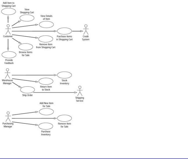
Create the Use Case diagram for the order−processing system. The steps for creating the diagram are outlined below. Your final Use Case diagram should look like Figure 4.22.
154
Chapter 4: Use Cases and Actors
Figure 4.22: E−Business System Use Case diagram
Exercise Steps:
Add the System Use Case Model Package, Use Case Diagram, Use Cases, and Actors
1.
Right−click the Use Case View package in the browser and select New → Package.
2.
Name the new package System Use Case Model.
3.
Right−click the System Use Case Model package and select New → Use Case Diagram.
4.
Name the new diagram Main.
5.
Double−click the Main Use Case diagram in the browser to open the diagram.
6.
Use the Use Case toolbar button to add a new use case to the diagram.
7.
155
Chapter 4: Use Cases and Actors
Name this new use case Add Item to Shopping Cart.
8.
Repeat steps 6 and 7 to add the remaining use cases to the diagram. The use cases are:
♦
View Shopping Cart
♦
View Details of Items
♦
Purchase Items in Shopping Cart
♦
Remove Item from Shopping Cart
♦
Browse Items for Sale
♦
Provide Feedback
♦
Stock Inventory
♦
Return Item to Stock
♦
Ship Order
♦
Add New Item for Sale
♦
Remove Item for Sale
♦
Purchase Inventory
9.
Use the Actor toolbar button to add a new actor to the diagram.
10.
Name this new actor Customer.
11.
Repeat steps 9 and 10 to add the remaining actors to the diagram. The actors are:
♦
156