
- •Table of Contents
- •Mastering UML with Rational Rose 2002
- •Chapter 1: Introduction to UML
- •Encapsulation
- •Inheritance
- •Polymorphism
- •What Is Visual Modeling?
- •Systems of Graphical Notation
- •Booch Notation
- •Object Management Technology (OMT)
- •Unified Modeling Language (UML)
- •Understanding UML Diagrams
- •Business Use Case Diagrams
- •Use Case Diagrams
- •Activity Diagrams
- •Sequence Diagrams
- •Collaboration Diagrams
- •Class Diagrams
- •Statechart Diagrams
- •Component Diagrams
- •Deployment Diagrams
- •Visual Modeling and the Software Development Process
- •Inception
- •Elaboration
- •Construction
- •Transition
- •Summary
- •Chapter 2: A Tour of Rose
- •What Is Rose?
- •Getting Around in Rose
- •Parts of the Screen
- •Exploring Four Views in a Rose Model
- •Use Case View
- •Logical View
- •Component View
- •Deployment View
- •Working with Rose
- •Creating Models
- •Saving Models
- •Exporting and Importing Models
- •Publishing Models to the Web
- •Working with Controlled Units
- •Using the Model Integrator
- •Working with Notes
- •Working with Packages
- •Adding Files and URLs to Rose Model Elements
- •Adding and Deleting Diagrams
- •Setting Global Options
- •Working with Fonts
- •Working with Colors
- •Summary
- •Chapter 3: Business Modeling
- •Introduction to Business Modeling
- •Why Model the Business?
- •Do I Need to Do Business Modeling?
- •Business Modeling in an Iterative Process
- •Business Actors
- •Business Workers
- •Business Use Cases
- •Business Use Case Diagrams
- •Activity Diagrams
- •Business Entities
- •Organization Unit
- •Where Do I Start?
- •Identifying the Business Actors
- •Identifying the Business Workers
- •Identifying the Business Use Cases
- •Showing the Interactions
- •Documenting the Details
- •Creating Business Use Case Diagrams
- •Deleting Business Use Case Diagrams
- •The Use Case Diagram Toolbar
- •Adding Business Use Cases
- •Business Use Case Specifications
- •Assigning a Priority to a Business Use Case
- •Viewing Diagrams for a Business Use Case
- •Viewing Relationships for a Business Use Case
- •Working with Business Actors
- •Adding Business Actors
- •Adding Actor Specifications
- •Assigning an Actor Stereotype
- •Setting Business Actor Multiplicity
- •Viewing Relationships for a Business Actor
- •Working with Relationships
- •Association Relationship
- •Generalization Relationship
- •Working with Organization Units
- •Adding Organization Units
- •Deleting Organization Units
- •Activity Diagrams
- •Adding an Activity Diagram
- •Adding Details to an Activity Diagram
- •Summary
- •Chapter 4: Use Cases and Actors
- •Use Case Modeling Concepts
- •Actors
- •Use Cases
- •Traceability
- •Flow of Events
- •Relationships
- •Use Case Diagrams
- •Activity Diagrams
- •Activity
- •Start and End States
- •Objects and Object Flows
- •Transitions
- •Synchronization
- •Working with Use Cases in Rational Rose
- •The Use Case Diagram Toolbar
- •Creating Use Case Diagrams
- •Deleting Use Case Diagrams
- •Adding Use Cases
- •Deleting Use Cases
- •Use Case Specifications
- •Naming a Use Case
- •Viewing Participants of a Use Case
- •Assigning a Use Case Stereotype
- •Assigning a Priority to a Use Case
- •Creating an Abstract Use Case
- •Viewing Diagrams for a Use Case
- •Viewing Relationships for a Use Case
- •Working with Actors
- •Adding Actors
- •Deleting Actors
- •Actor Specifications
- •Naming Actors
- •Assigning an Actor Stereotype
- •Setting Actor Multiplicity
- •Creating an Abstract Actor
- •Viewing Relationships for an Actor
- •Viewing an Actor's Instances
- •Working with Relationships
- •Association Relationship
- •Includes Relationship
- •Extends Relationship
- •Generalization Relationship
- •Working with Activity Diagrams
- •The Activity Diagram Toolbar
- •Creating Activity Diagrams
- •Deleting Activity Diagrams
- •Exercise
- •Problem Statement
- •Create a Use Case Diagram
- •Summary
- •Chapter 5: Object Interaction
- •Interaction Diagrams
- •What Is an Object?
- •What Is a Class?
- •Where Do I Start?
- •Finding Objects
- •Finding the Actor
- •Using Interaction Diagrams
- •Sequence Diagrams
- •The Sequence Diagram Toolbar
- •Collaboration Diagrams
- •The Collaboration Diagram Toolbar
- •Working with Actors on an Interaction Diagram
- •Working with Objects
- •Adding Objects to an Interaction Diagram
- •Deleting Objects from an Interaction Diagram
- •Setting Object Specifications
- •Naming an Object
- •Mapping an Object to a Class
- •Setting Object Persistence
- •Using Multiple Instances of an Object
- •Working with Messages
- •Adding Messages to an Interaction Diagram
- •Adding Messages to a Sequence Diagram
- •Deleting Messages from a Sequence Diagram
- •Reordering Messages in a Sequence Diagram
- •Message Numbering in a Sequence Diagram
- •Viewing the Focus of Control in a Sequence Diagram
- •Adding Messages to a Collaboration Diagram
- •Deleting Messages from a Collaboration Diagram
- •Message Numbering in a Collaboration Diagram
- •Adding Data Flows to a Collaboration Diagram
- •Setting Message Specifications
- •Naming a Message
- •Mapping a Message to an Operation
- •Setting Message Synchronization Options
- •Setting Message Frequency
- •End of a Lifeline
- •Working with Scripts
- •Switching Between Sequence and Collaboration Diagrams
- •Exercise
- •Problem Statement
- •Create Interaction Diagrams
- •Summary
- •Chapter 6: Classes and Packages
- •Logical View of a Rose Model
- •Class Diagrams
- •What Is a Class?
- •Finding Classes
- •Creating Class Diagrams
- •Deleting Class Diagrams
- •Organizing Items on a Class Diagram
- •Using the Class Diagram Toolbar
- •Working with Classes
- •Adding Classes
- •Class Stereotypes
- •Analysis Stereotypes
- •Class Types
- •Interfaces
- •Web Modeling Stereotypes
- •Other Language Stereotypes
- •Class Specifications
- •Naming a Class
- •Setting Class Visibility
- •Setting Class Multiplicity
- •Setting Storage Requirements for a Class
- •Setting Class Persistence
- •Setting Class Concurrency
- •Creating an Abstract Class
- •Viewing Class Attributes
- •Viewing Class Operations
- •Viewing Class Relationships
- •Using Nested Classes
- •Viewing the Interaction Diagrams That Contain a Class
- •Setting Java Class Specifications
- •Setting CORBA Class Specifications
- •Working with Packages
- •Adding Packages
- •Deleting Packages
- •Exercise
- •Problem Statement
- •Creating a Class Diagram
- •Summary
- •Chapter 7: Attributes and Operations
- •Working with Attributes
- •Finding Attributes
- •Adding Attributes
- •Deleting Attributes
- •Setting Attribute Specifications
- •Setting the Attribute Containment
- •Making an Attribute Static
- •Specifying a Derived Attribute
- •Working with Operations
- •Finding Operations
- •Adding Operations
- •Deleting Operations
- •Setting Operation Specifications
- •Adding Arguments to an Operation
- •Specifying the Operation Protocol
- •Specifying the Operation Qualifications
- •Specifying the Operation Exceptions
- •Specifying the Operation Size
- •Specifying the Operation Time
- •Specifying the Operation Concurrency
- •Specifying the Operation Preconditions
- •Specifying the Operation Postconditions
- •Specifying the Operation Semantics
- •Displaying Attributes and Operations on Class Diagrams
- •Showing Attributes
- •Showing Operations
- •Showing Visibility
- •Showing Stereotypes
- •Mapping Operations to Messages
- •Mapping an Operation to a Message on an Interaction Diagram
- •Exercise
- •Problem Statement
- •Add Attributes and Operations
- •Summary
- •Chapter 8: Relationships
- •Relationships
- •Types of Relationships
- •Finding Relationships
- •Associations
- •Using Web Association Stereotypes
- •Creating Associations
- •Deleting Associations
- •Dependencies
- •Creating Dependencies
- •Deleting Dependencies
- •Package Dependencies
- •Creating Package Dependencies
- •Deleting Package Dependencies
- •Aggregations
- •Creating Aggregations
- •Deleting Aggregations
- •Generalizations
- •Creating Generalizations
- •Deleting Generalizations
- •Working with Relationships
- •Setting Multiplicity
- •Using Relationship Names
- •Using Stereotypes
- •Using Roles
- •Setting Export Control
- •Using Static Relationships
- •Using Friend Relationships
- •Setting Containment
- •Using Qualifiers
- •Using Link Elements
- •Using Constraints
- •Exercise
- •Problem Statement
- •Adding Relationships
- •Summary
- •Chapter 9: Object Behavior
- •Statechart Diagrams
- •Creating a Statechart Diagram
- •Adding States
- •Adding State Details
- •Adding Transitions
- •Adding Transition Details
- •Adding Special States
- •Using Nested States and State History
- •Exercise
- •Problem Statement
- •Create a Statechart Diagram
- •Summary
- •Chapter 10: Component View
- •What Is a Component?
- •Types of Components
- •Component Diagrams
- •Creating Component Diagrams
- •Adding Components
- •Adding Component Details
- •Adding Component Dependencies
- •Exercise
- •Problem Statement
- •Summary
- •Chapter 11: Deployment View
- •Deployment Diagrams
- •Opening the Deployment Diagram
- •Adding Processors
- •Adding Processor Details
- •Adding Devices
- •Adding Device Details
- •Adding Connections
- •Adding Connection Details
- •Adding Processes
- •Exercise
- •Problem Statement
- •Create Deployment Diagram
- •Summary
- •Chapter 12: Introduction to Code Generation and Reverse Engineering Using Rational Rose
- •Preparing for Code Generation
- •Step One: Check the Model
- •Step Two: Create Components
- •Step Three: Map Classes to Components
- •Step Five: Select a Class, Component, or Package
- •Step Six: Generate Code
- •What Gets Generated?
- •Introduction to Reverse Engineering Using Rational Rose
- •Model Elements Created During Reverse Engineering
- •Summary
- •Chapter 13: ANSI C++ and Visual C++ Code Generation and Reverse Engineering
- •Generating Code in ANSI C++ and Visual C++
- •Converting a C++ Model to an ANSI C++ Model
- •Class Properties
- •Attribute Properties
- •Operation Properties
- •Package (Class Category) Properties
- •Component (Module Specification) Properties
- •Role Properties
- •Generalization Properties
- •Class Model Assistant
- •Component Properties
- •Project Properties
- •Visual C++ and ATL Objects
- •Generated Code
- •Code Generated for Classes
- •Code Generated for Attributes
- •Code Generated for Operations
- •Visual C++ Code Generation
- •Reverse Engineering ANSI C++
- •Reverse Engineering Visual C++
- •Summary
- •Overview
- •Introduction to Rose J
- •Beginning a Java Project
- •Selecting a Java Framework
- •Linking to IBM VisualAge for Java
- •Linking to Microsoft Visual J++
- •Project Properties
- •Class Properties
- •Attribute Properties
- •Operation Properties
- •Module Properties
- •Role Properties
- •Generating Code
- •Generated Code
- •Classes
- •Attributes
- •Operations
- •Bidirectional Associations
- •Unidirectional Associations
- •Associations with a Multiplicity of One to Many
- •Associations with a Multiplicity of Many to Many
- •Reflexive Associations
- •Aggregations
- •Dependency Relationships
- •Generalization Relationships
- •Interfaces
- •Java Beans
- •Support for J2EE
- •EJBs
- •Servlets
- •JAR and WAR Files
- •Automated J2EE Deployment
- •Reverse Engineering
- •Summary
- •Starting a Visual Basic Project
- •Class Properties
- •Attribute Properties
- •Operation Properties
- •Module Specification Properties
- •Role Properties
- •Generalization Properties
- •Generated Code
- •Classes
- •Attributes
- •Operations
- •Bidirectional Associations
- •Unidirectional Associations
- •Associations with a Multiplicity of One to Many
- •Associations with a Multiplicity of Many to Many
- •Reflexive Associations
- •Aggregations
- •Dependency Relationships
- •Generalization Relationships
- •Reverse Engineering
- •Summary
- •Overview
- •Introduction to XML DTD
- •Elements
- •Attributes
- •Entities and Notations
- •Project Properties
- •Class Properties
- •Attribute Properties
- •Role Properties
- •Component Properties
- •Generating Code
- •Generated Code
- •Classes
- •Attributes
- •Reverse Engineering DTD
- •Summary
- •Project Properties
- •Class Properties
- •Attribute Properties
- •Operation Properties
- •Module Properties
- •Association (Role) Properties
- •Dependency Properties
- •Generated Code
- •Classes
- •Attributes
- •Operations
- •Bidirectional Associations
- •Unidirectional Associations
- •Associations with a Multiplicity of One to Many
- •Associations with a Multiplicity of Many to Many
- •Associations with Bounded Multiplicity
- •Reflexive Associations
- •Aggregations
- •Dependency Relationships
- •Generalization Relationships
- •Reverse Engineering CORBA Source Code
- •Summary
- •Chapter 18: Rose Data Modeler
- •Object Models and Data Models
- •Creating a Data Model
- •Logic in a Data Model
- •Adding a Database
- •Adding Tablespaces
- •Adding a Schema
- •Creating a Data Model Diagram
- •Creating Domain Packages and Domains
- •Adding Tables
- •Adding Columns
- •Setting a Primary Key
- •Adding Constraints
- •Adding Triggers
- •Adding Indexes
- •Adding Stored Procedures
- •Adding Relationships
- •Adding Referential Integrity Rules
- •Working with Views
- •Generating an Object Model from a Data Model
- •Generating a Data Model from an Object Model
- •Generating a Database from a Data Model
- •Updating an Existing Database
- •Reverse Engineering a Database
- •Summary
- •Chapter 19: Web Modeling
- •Modeling a Web Application
- •Web Class Stereotypes
- •Relationships
- •Reverse Engineering a Web Application
- •Generating Code for a Web Application
- •Summary
- •Appendix: Getting Started with UML
- •Building a Business Use Case Diagram
- •Building a Workflow (Activity) Diagram
- •Building a Use Case Diagram
- •Building an Interaction Diagram
- •Building a Class Diagram
- •Web Modeling
- •Adding Class Relationships
- •Building a Statechart Diagram
- •Building a Component Diagram
- •Building a Deployment Diagram

Chapter 4: Use Cases and Actors
called "Repair Plane."
Every system use case must be traced back to a business use case, but not all business use cases will be supported by system use cases. Hypothetically, if the business use case called "Unload Passengers and Luggage" is a completely manual process, then it would not have any supporting system use cases at all. Here is an example of how system use cases might map to business use cases:
Business Use Case |
System Use Cases |
Repair Plane |
Enter Problem; Check Inventory for Parts; Receive Part from |
|
Inventory; Order Part; Schedule Maintenance |
Load Supplies on Plane |
Determine Needed Supplies; Check Supply Availability; Reserve |
|
Supplies; Receive Supplies |
Perform Preflight Safety Check |
Confirm Luggage Inspection; Confirm Passenger Check−In; Inspect |
|
Plane Exterior; Check Status of Emergency Equipment |
If you are using a requirements management tool, such as Rational's Requisite Pro, you can map the system use cases to business use cases directly in the tool. If not, it is important to set up a process, even in a simple spreadsheet or database, to ensure that the system use cases are mapped to business use cases. The real purpose of traceability is ensuring that, at the end of the day when the system is built and implemented, all of the requirements are met and all of the code can be traced back to a requirement.
After the system use cases are traced to business use cases, the next step is to trace the requirements to the system use cases. Each functional requirement must be traced to a system use case, because the system use cases describe the functionality that will be provided by the system. The system design is driven by the use cases, so if a requirement is not traced to a use case, it will not be considered in the design and may not end up in the final system.
Note Notice that we said functional requirements. There are non−functional requirements, such as system response time or the number of concurrent users supported that do not need to be traced to system use cases. These are typically maintained in a Supplementary Specification document.
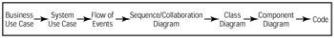
Again, if you are using a tool such as Requisite Pro, you can trace the requirements to use cases in the tool. If not, set up a method to ensure that each requirement is traced to a use case. As we go through the whole process, traceability should be shown as in Figure 4.1.
Figure 4.1: Traceability through the life cycle
Flow of Events
The use cases begin to describe what your system will do. To actually build the system, though, you'll need more specific details. These details are written as the flow of events. The purpose of the flow of events is to document the flow of logic through the use case. This document will describe in detail what the user of the system will do and what the system itself will do.
Although it is detailed, the flow of events is still implementation−independent. You can assume as you are writing the flow that there will be an automated system. However, you shouldn't yet be concerned with whether the system will be built in C++, PowerBuilder, or Java. The goal here is describing what the system will do, not how the system will do it. The flow of events typically includes:
∙
108
Chapter 4: Use Cases and Actors
A brief description
∙
Preconditions
∙
Primary flow of events
∙
Alternate flow of events
∙
Postconditions
Let's look at these items one at a time.
Description
Each use case should include a short description that explains what the use case will do. The Purchase Ticket use case from our airline example might have a description like the following: The Purchase Ticket use case will allow a customer to view available flight information, check availability, and purchase a ticket with a credit card.
The description should be short and to the point, but should include the different types of users who will be executing the use case and the end result the user expects to achieve through the use case. As the project progresses (especially with a very long project), these use case definitions will help the whole team remember why each use case is included in the project and what the use case is intended to do. They also help reduce confusion among the team members by documenting a clear purpose for the use case.
Preconditions
The preconditions for a use case list any conditions that have to be met before the use case can start at all. For example, a precondition might be that another use case has been executed or that the user has the necessary access rights to run the current use case. Not all use cases will have preconditions.
Use Case diagrams aren't intended to show in which order the use cases are executed. Preconditions, however, can be used to document some of this type of information. For example, the precondition for one use case may be that another use case has run.
Primary and Alternate Flow of Events
The specific details of the use case are described in the primary and alternate flow of events. The flow of events describes, step−by−step, what will happen to execute the functionality in the use case. The flow of events focuses on what the system will do, not how it will do it, and is written from the user's perspective. The primary and alternate flow of events include:
∙
How the use case starts
∙
The various paths through the use case
∙ |
109 |
Chapter 4: Use Cases and Actors
The normal, or primary, flow through the use case
∙
Any deviations from the primary flow, known as alternate flows, through the use case
∙
Any error flows
∙
How the use case ends
Along with the flow of events in text form, activity diagrams are frequently used. In this section, we'll talk about the option of using text. We'll go over activity diagrams later in this chapter.
There are three types of flows: the primary, alternate, and error flows. The primary flow is the "happy day" scenario, or the most frequently used path through the use case. When purchasing a ticket, the primary flow is a successful ticket purchase. Alternate flows are deviations from the primary flow that do not suggest an error condition. For example, a customer may purchase a ticket using frequent−flyer miles, the customer's credit card may not be valid, or the requested flight may not be available. Each of these is a legitimate scenario that the system will be expected to handle, but doesn't suggest that something has gone wrong with the system itself. Finally, error flows are deviations from the primary or alternate flows that suggest some sort of error condition. For example, the system may be unable to verify the credit card or the flight availability. Error flows suggest that there is a problem with the system itself.
Using our "Purchase Ticket" use case example, the flow of events might look like the steps in the following sections.
Primary Flow
The steps for the primary flow of events include:
1.
The use case begins when the customer selects the option to view flight information.
2.
The system prompts for the departure and destination cities and the departure and return dates.
3.
The user enters the departure and destination city, departure date, and return date.
4.
The system displays a list of available flights, including the fare.
A1: There are no available flights.
5.
The user selects the flight they would like to reserve.
6.
The system displays all available fare options for that flight.
7.
110
Chapter 4: Use Cases and Actors
The user selects the fare option they would like to reserve.
A2: The user selects a free ticket through frequent−flyer membership.
8.
The system displays the fare that the user will pay.
9.
The user confirms the rate.
10.
The system prompts for a credit card type, number, name, and expiration date.
11.
The user enters the card type, number, name, and expiration date.
12.
The system submits the credit purchase.
A6: Account not found
A7: Insufficient funds
E1: Credit system not accessible
13.
The system reserves a seat on the plane for the user.
14.
The system generates and displays a confirmation code to the user.
15.
The user confirms receipt of the code.
16.
The use case ends.
Alternate Flows
A1: No available flights
1.
The system displays a message that there are no available flights for the departure and destination cities, departure date, and return date entered.
2.
The user confirms the message.
3.
The flow returns to the primary flow, step 2.
111
Chapter 4: Use Cases and Actors
A2: Free ticket through frequent−flyer membership
1.
The system prompts for the frequent−flyer number.
2.
The user enters the number.
3.
The system confirms the validity of the number.
A3: Invalid number
4.
The system confirms that there are enough miles on this membership to qualify for the free ticket.
A4: Not enough miles to qualify for a free ticket
A5: No frequent−flyer tickets available
5.
The ticket fare is set to $0.
6.
The flow returns to the primary flow, step 8.
A3: Invalid frequent−flyer number
1.
The system displays a message that the frequent−flyer number is invalid.
2.
The user reenters the number or selects the option to cancel the frequent−flyer request.
3.
If the user reenters the number, the flow returns to step 1 of alternate flow A2.
4.
If the user cancels the frequent−flyer request, the flow returns to step 6 of the primary flow.
A4: Not enough frequent−flyer miles to qualify for free ticket
1.
The system displays a message that there are not enough miles to qualify. The message contains the required number of miles and the number of miles available.
2.
The flow returns to step 6 of the primary flow.
A5: No frequent−flyer tickets available
1.
112
Chapter 4: Use Cases and Actors
The system displays a message that there are no frequent−flyer tickets available for the selected flight.
2.
The flow returns to step 6 of the primary flow.
A6: Credit account not found
3.
The system displays a message that the credit account was not found.
4.
The flow returns to step 10 of the primary flow.
A7: Insufficient funds
1.
The system displays a message that there were not enough funds on the card to complete the transaction.
2.
The flow returns to step 10 of the primary flow.
Error Flows
E1: Credit system not available
1.
The system displays a message that the credit system is not available.
2.
The flow returns to step 10 of the primary flow.
Notice the pattern in the flow of events: the user does something, then the system does something in response, then the user does something, then the system responds, and so on. Keeping to this pattern as much as possible helps you ensure that you have a complete understanding of how the conversation between the user and the system should flow. When documenting the flow of events, you can use numbered lists as we have done here, text in paragraph form, bulleted lists, or even flowcharts. With the user/system pattern, another way to document the flow is by using a table:
User Action |
System Response |
Select option to view flight information |
Prompt for departure and destination cities, departure |
|
and arrival dates |
Enter departure and destination cities, departire and |
Display flight number, departure time, and arrival |
arrival dates |
time for available flights |
… |
… |
… |
… |
… |
… |
… |
… |
113