

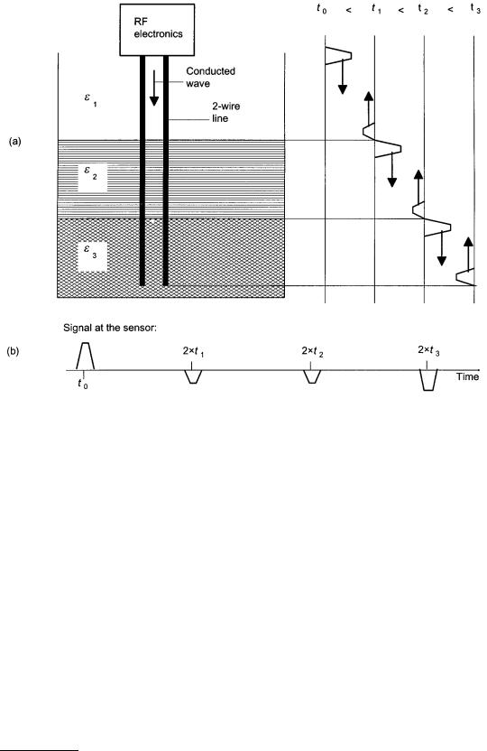
FIGURE 11.9 Principle of operation of a wire-conducting high-frequency level measurement system. (a) An electrical pulse is generated (time t0) and a two-wire line guides the electromagnetic wave. At every position where the surrounding permittivity ε changes, a part of the wave is sharply reflected (time t1) back to the sensor. The wave propagates along the entire line and is reflected a second time (t2) at the interface between the two liquids, and a third time at the end of the line. (b) The signal delay times (2t1, 2t2, and 2t3) represent the positions of the interfaces with respect to the end of the line, which can be used as a reference. The signal polarity is inverted due to the reflection from lower to higher permittivity. The time scale is arbitrary.
This is not the case if the waves propagate within an electromagnetic waveguide, like a vertical tube dipping into the liquid, called a stilling well. Here, the propagation is nearly without losses.
An alternative method using electromagnetic waves is to propagate them in a cable. Figure 11.9(a) illustrates the operation with a cable dipped into the liquid or bulk material. Where the dielectric permittivity of the surrounding medium changes, part of the wave is reflected. This method can be applied to interface measurements too. Figure 11.9 shows the signals in an application with a two-phase product. This method is called “time domain reflectometry” (TDR).
Laser/Light
Lasers and light-emitting diodes produce electromagnetic waves of very short wavelength (less than 2 m), which can also be used for time-of-flight measurements, similar to the described microwave methods. Preferred laser signals are (1) short pulses of less than 1 ns duration, or (2) lasers with amplitudemodulated intensity with frequencies of some megahertz. For more details about laser operation and interferometry methods, refer to Chapter 6, Section 5 of this handbook.
© 1999 by CRC Press LLC
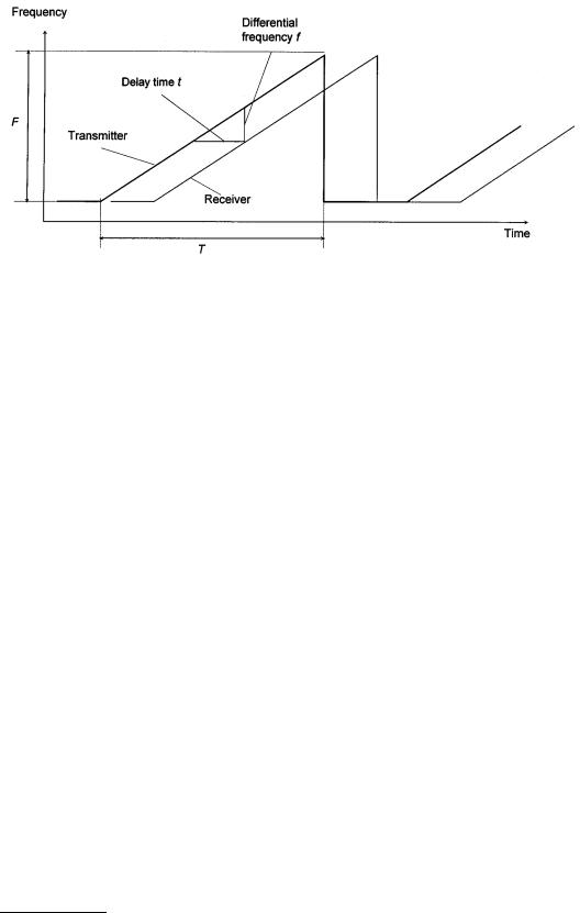
FIGURE 11.10 Operation characteristics of FMCW radar. The frequency of the transmitter changes linearly by time in an interval (sweep). The received signal has the same form, but is time-delayed. At every point of the sweep, the differential frequency is constant and proportional to the time delay. Time and frequency scales are arbitrary.
Laser systems are very precise and can achieve accuracies better than 1 mm. Because the laser beam is very narrow, such level measurement systems can be installed without influence of tank internals. Some practical disadvantages of laser level measurement are: (1) it functions as does your eye to see the product’s surface and therefore fails if dust, smoke, etc. are present; (2) it is sensitive to dirt on the optical sensors; and (3) the equipment is expensive.
Commonly Used Evaluation Methods
Due to the great benefits of contactless time-of-flight measurement, some typical methods have been evaluated for level gaging within the last few years, mainly in radar techniques [8].
Frequency-Modulated Continuous Wave Radar
Because the flight times in typical level applications are very short (a resolution of 1 mm requires a 7 ps time resolution), it is difficult to evaluate information directly in the time domain. By modulation of the microwave signals, the time delay is transformed into the frequency domain, obtaining low-frequency signals. For general information about modulation, see Chapter 81 of this handbook.
Therefore, Frequency Modulated Continuous Wave (FMCW) radar has been established as the dominant technique. FMCW radar utilizes a linearly frequency-modulated microwave signal; the transmission frequency rises linearly in a time interval T. The frequency difference in this interval is called the frequency sweep F.
Figure 11.10 shows the principle of FMCW radar. Due to the time delay during signal propagation, the transmitted frequency changes such that the difference between the momentary transmitted frequency and the received frequency, a low-frequency signal is obtained. The frequency f of that signal (typically up to a few kilohertz) is proportional to the reflector distance d (see Figure 11.6); in this method, therefore, the delay t is transformed into a frequency f :
f = |
F |
t = |
F |
|
2d |
d = |
f c T |
(11.16) |
|
|
|
c |
2 F |
||||
|
T T |
|
|
|
||||
In Equation 11.16, c is the speed of light and F/T is the sweep velocity; see Figure 11.10.
Figure 11.11 shows a basic circuit block diagram of an FMCW radar system. Because the resultant signal frequencies are low, further signal processing is technically simple and very accurate. Normally,
© 1999 by CRC Press LLC
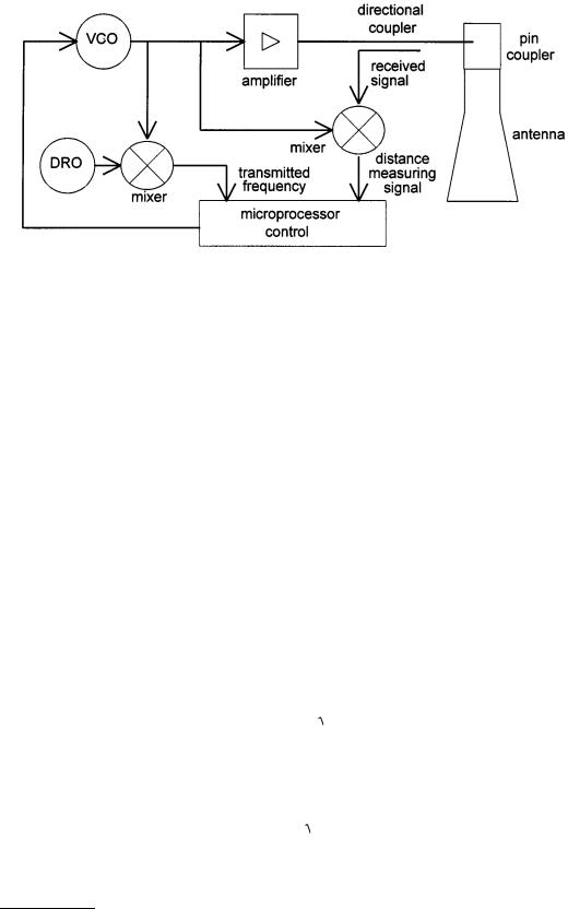
FIGURE 11.11 Basic circuit block diagram of an FMCW radar system: a microprocessor controls a voltagecontrolled oscillator (VCO), such that the desired frequency sweep is obtained. This signal is amplified and fed into the transmitting antenna. The instantaneous frequency must be measured in order to ensure good sweep linearity. This is accomplished by counting the frequency after it has been mixed with the known frequency of a dielectric resonance oscillator (DRO). A directional coupler decouples the received signal, which is mixed with the transmission signal and processed by the microprocessor.
evaluation is by means of digital signal processing. For more information about signal processing techniques using spectrum analysis, refer to Chapter 83 of this handbook.
Time-of-Flight Through Product
Alternatively, the propagation time of the waves through a weakly absorbing liquid or bulk material of low permittivity εr can be measured, as well as the propagation through the air. In cases where the reflection from the interface between air and the upper surface of the product is poor, part of the signal travels through the liquid and is reflected a second time at the tank bottom or at an interface between two liquids (e.g., oil on water).
Figure 11.12 demonstrates this technique. The evaluation is done in the following four steps:
1.Where microwaves in the tank atmosphere of height d are propagated at the speed of light c, microwaves in the medium (relative permittivity = εr, height L) are propagated at a slower velocity v.
2.Hence, the reflection r2 from the tank bottom appears to be shifted downward, and the apparent tank height hv is greater than the true height h.
3.The transit time in the medium is t1 = L/v, where for the same distance in an empty tank would be t0 = L/c. The ratio of apparent “thickness layer” (hv – d) to true filling height (h – d) therefore corresponds to the ratio of the wave propagation rates:
hv |
− d |
= |
c |
= εr |
(11.17) |
|
h − d |
v |
|||||
|
|
|
||||
4. When εr, h, and hv are known, distance d and, from that, filling height L can be calculated exactly:
L = h − d = |
hv |
− h |
|
|
|
(11.18) |
|
|
|
||
εr −1
By this method, a direct level measurement — not a distance measurement — is attained. It can even be applied when signal r1 from the surface of the medium is no longer measurable. The evaluation of
© 1999 by CRC Press LLC