


For techniques of weight measurement, refer to Chapter 20 of this handbook.
This method has severe disadvantages when the tank is not inside a building. Outside, wind forces and the weight of snow and rain can cause errors.
11.2 Time-of-Flight Measurements
An indirect measurement of level is evaluating the time-of-flight of a wave propagating through the atmosphere above the liquid or solid. This is primarily a distance measurement; the level can then be calculated accordingly. The increasing demand of industry for nonintrusive continuous level gaging systems has been instrumental in accelerating the development of technologies using time-of-flight measurements [7].
Basic Principle
Although different types of physical waves (acoustic or electromagnetic) are applied, the principle of all these methods is the same: a modulated signal is emitted as a wave toward the product, reflected at its surface and received by a sensor, which in many cases is the same, (e.g., the ultrasonic piezoelectric transducer or the radar antenna). Figure 11.6 demonstrates the principle of operation. The measuring system evaluates the time-of-flight t of the signal:
t = |
2 d |
(11.12) |
|
v |
|||
|
|
where v is the propagation velocity of the waves.
One can generate an unmodulated pulse, a modulated burst as in Figure 11.6(b), or special forms. Table 11.1 lists the main properties of the three preferred types of waves, used for time-of-flight level gaging.
The very short time spans of only a few nanoseconds for radar and laser measurement techniques require the use of time expansion by sampling (see Chapter 85 of this handbook) or special evaluation methods (see below).
Ultrasonic
Ultrasonic waves are longitudinal acoustic waves with frequencies above 20 kHz. Ultrasonic waves need a propagation medium, which for level measurements is the atmosphere above the product being measured. Sound propagates with a velocity of about 340 m s–1 in air; but this value is highly dependent on temperature and composition of the gas, and also on its pressure (see Chapter 6, Section 7 of this handbook). In vacuum, ultrasonic waves cannot propagate. In practice, the reflection ratio is nearly 100% at the product’s surface (e.g., at transitions gas/liquid or gas/solid). Piezoelectric transducers (see Chapter 26, Section 3 of this handbook) are utilized as emitter and detector for ultrasonic waves, a membrane coupling it to the atmosphere. The sensor is installed as in Figure 11.1(b), the signal form is as in Figure 11.6(b). Level gaging is, in principle, also possible with audible sound 16 Hz to 20 kHz or infrasonic waves less than 16 Hz.
Another procedure is to propagate the waves within the liquid by a sensor mounted at the bottom of the tank. The velocity of sound in the liquid must be known, considering the dependence on temperature and type of liquid. This method is similar to an echo sounder on ships for measuring the water depth. For more information about time-of-flight ultrasound evaluation techniques, refer to Chapter 6, Section 7 of this handbook.
Microwaves
Microwaves are generally understood to be electromagnetic waves with frequencies above 2 GHz and wavelengths of less than 15 cm. For technical purposes, microwave frequencies are used up to max. 120 GHz; in practice, the range around 10 GHz (X-band) is preferred.
© 1999 by CRC Press LLC
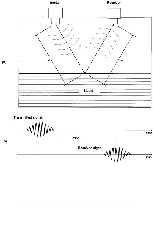
FIGURE 11.6 (a)Representation of time-of-flight measurements. The emitter couples a wave (ultrasonic or electromagnetic) into the atmosphere that propagates the wave toward the liquid. Its surface reflects the wave and a sensor receives it. (b) Due to the propagation velocity v, a time delay is measured between emission and receipt of the signal. This example is characterized by a modulated burst. The time scale is arbitrary.
TABLE 11.1 Properties of the wave types for time-of-flight measuring.
Principle |
Wave Velocity |
Avg. Carrier Frequency |
Wavelength |
Avg. Burst Time |
|
|
|
|
|
Ultrasonic |
340 m s–1 |
50 kHz |
7 mm |
1 ms |
Radar |
300,000 km s–1 |
10 GHz |
3 cm |
1 ns |
Laser |
300,000 km s–1 |
300 THz |
1 m |
1 ns |
© 1999 by CRC Press LLC
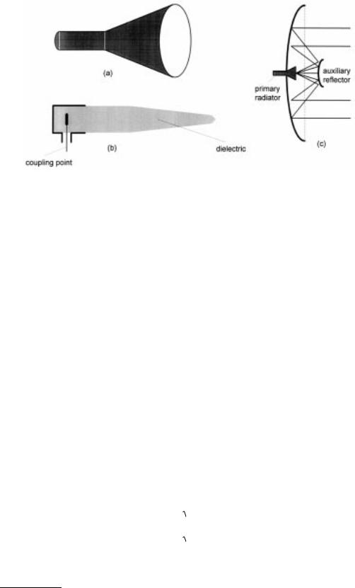
FIGURE 11.7 Practical antenna forms used for radar level instruments: (a) conical horn antenna, (b) dielectric rod antenna, and (c) parabolic mirror with a small antenna as primary radiator and an auxiliary reflector giving a very small beam angle (so-called Cassegrain model).
The usually applied time-of-flight measurements with microwaves are RADAR-based [8, 9]. The term “RADAR” is generally understood to mean a method by means of which short electromagnetic waves are used to detect distant objects and determine their location and movement. It is an acronym from RAdio Detection And Ranging. Figure 11.7 shows preferred antenna forms. They are usually combined with a compact sensor, as in Figure 11.8. For level measuring systems, a small radiation angle is desirable in order to avoid interfering reflections from the tank wall or tank internals as much as possible. The larger the aperture area, the smaller the radiation angle and the higher the antenna gain. The power balance is given by the general radar equation:
|
P = |
PT GT RGR |
(11.13) |
|
|
||
|
R |
D2 |
|
|
|
|
|
where PR |
= received power |
|
|
PT |
= transmitted power |
|
|
GT = transmitting antenna gain |
|
|
|
R |
= reflection factor of target |
|
|
GR = receiving antenna gain |
|
|
|
D2 |
= propagation loss to and from the surface, due to power density decrease and atmospheric |
||
influences
The reflection factor R of the product’s surface is dependent on the dielectric permittivity εr of the liquid or bulk material:
æ |
er |
-1ö2 |
|
|
R = |
è |
|
ø |
(11.14) |
|
|
+1ö2 |
||
æ |
er |
|
||
è |
|
ø |
|
|
© 1999 by CRC Press LLC
FIGURE 11.8 Design of a compact industrial level radar system. The converter above the flange includes the complete microwave circuitry, signal processing stages, microprocessor control, display, power supply, and output signal [6].
In level measurement situations, the reflecting area is so large that it intersects the beam cross section completely; therefore, D2 is approximately proportional with distance d2. Thus also, the received power decreases proportionately with d2, as derived in [8]:
P |
1 |
(11.15) |
R d2
© 1999 by CRC Press LLC