

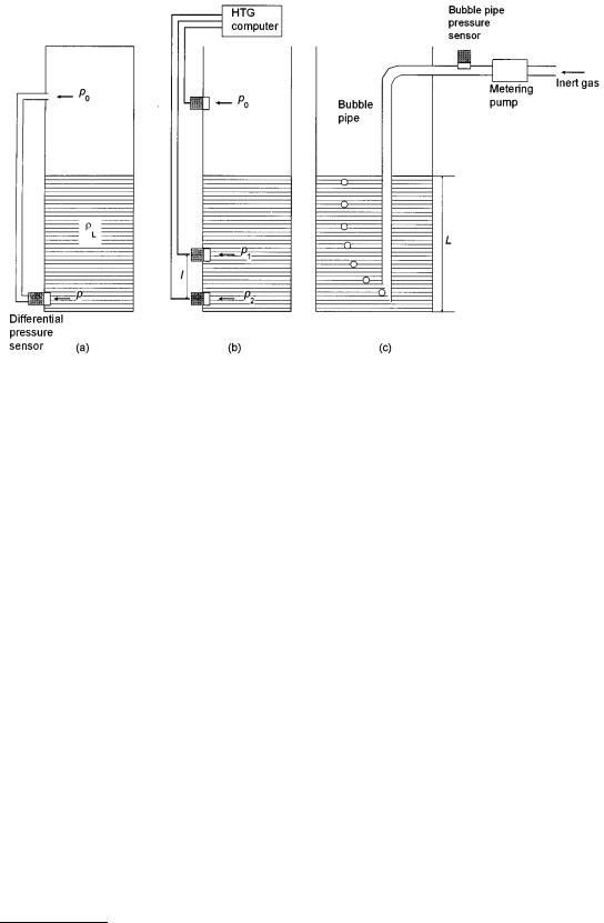
FIGURE 11.5 Level gaging by hydrostatic pressure measurement. The bottom pressure p is proportional to level. (a) The atmospheric pressure p0 can be taken into consideration by a differential measurement. The low side of the differential pressure sensor is connected via a thin pipe to the top of the tank. (b) A differential measurement within the liquid is called “hydrostatic tank gaging, HTG” and can be used to for compensate errors due to density variations of the liquid. The signals from all three sensors are evaluated by a computer. (c) With a so-called “bubble tube,” the sensor can be mounted on the top of the tank: an inert gas is injected into the tube such that bubbles of gas escape from the end of the tube. The flow rate of the gas is constant so the head pressure in the system can be measured at the inlet of the pipe.
rL |
= |
p2 - p1 |
Þ L = |
p2 - p0 |
l |
(11.9) |
|
g l |
p2 - p1 |
||||||
|
|
|
|
|
A system of this configuration is often called “hydrostatic tank gaging” (HTG). Figure 11.5(c) shows a further arrangement, called “bubble tube,” in which the bottom pressure is transmitted to the top of the tank. This is often used for level gaging if the sensor cannot be mounted at the bottom of the tank. It requires a tank with pressure equalization due to the steady insertion of inert gas.
Balance Method
Here simply the weight F of the complete tank is measured, dependent on the level L:
F = F0 + g A LrL |
(11.10) |
where F0 is the weight of the empty tank and A the cross-sectional area, which is assumed to be constant throughout the tank height. In order to measure the weight force correctly, it is necessary to isolate the complete tank mechanically. For precise measurements, the buoyancy in air must be taken into consideration:
F = F0 + g A L(rL - rA ) Û |
L = |
F - F0 |
(11.11) |
||
g A(rL |
- rA ) |
||||
|
|
|
|||
© 1999 by CRC Press LLC