
Drawing and detailing with SolidWorks
.pdf
www.GetPedia.com
Drawing and Detailing with SolidWorks
A Workbook for SolidWorks 2001/2001Plus
by David C. Planchard and Marie P. Planchard
A Competency Based Approach Referencing the ASME Y14 Engineering
Drawing and Related Documentation Practices
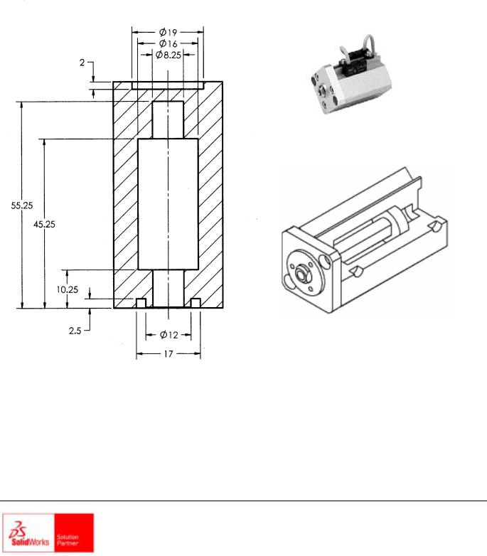
COMPACT
AIR CYLINDER
CYLINDER ASSEMBLY
SECTION A-A
SDC
PUBLICATIONS
Schroff Development Corporation
www.schroff.com www.schroff-europe.com
Drawing and Detailing with SolidWorks 2001/2001Plus |
Drawing Template and Sheet Format |
Project 1
Drawing Template and Sheet Format
Below are the desired outcomes and usage competencies based upon the completion of this Project. Note: The foundation of a SolidWorks drawing is the Drawing Template.
Project Desired Outcomes: |
Usage Competencies: |
|
|
Empty Drawing Templates |
Apply Drawing Properties to reflect the |
|
ASME Y14 Engineering Drawing and |
Custom Sheet Format |
Related Drawing Practices. |
Custom Drawing Template |
|
Knowledge and understanding of Drawing |
|
|
Templates and Sheet Formats. |
|
|
|
Wisdom of importing an AutoCAD |
|
drawing to create and modify a custom |
|
Sheet Format. |
|
|
PAGE 1-1

Drawing Template and Sheet Format |
Drawing and Detailing with SolidWorks 2001/2001Plus |
Notes
PAGE 1-2
Drawing and Detailing with SolidWorks 2001/2001Plus |
Drawing Template and Sheet Format |
Project 1 – Drawing Template and Sheet Format
Project Objective
Create a C-size Drawing Template. Create an A-size Drawing Template.
Project Situation
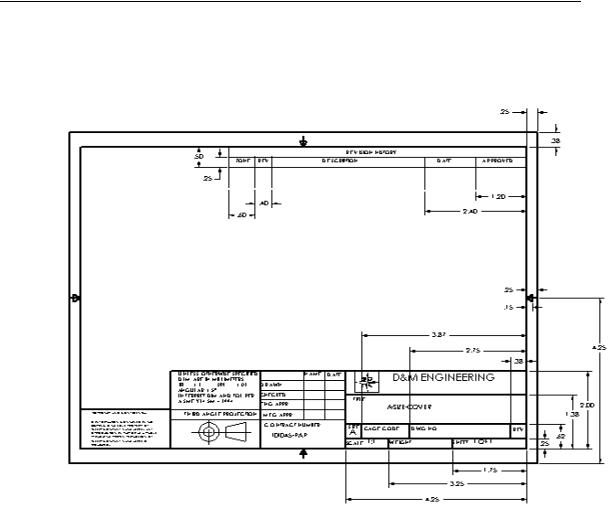
As the designer, your responsibilities include developing drawings that adhere to the ASME Y14 American National Standard for Engineering Drawing and Related Documentation Practices. The foundation for a SolidWorks drawing is the Drawing Template. Drawing size, drawing standards, units and other properties are defined in the Drawing Template. Sheet Formats contain the following: border, title block, revision block, company name, logo, SolidWorks Properties and Custom Properties.
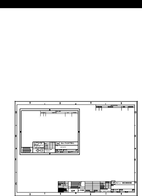
You are under time constraints to complete the project on schedule. Create a SolidWorks custom Sheet Format. Import an existing AutoCAD C-size drawing.
Create a custom C-size Drawing Template and an A-size Drawing Template.
A-Size Drawing Template with
SolidWorks Sheet Format
C-Size Drawing Template with
Imported AutoCAD Sheet Format
PAGE 1-3
Drawing Template and Sheet Format |
Drawing and Detailing with SolidWorks 2001/2001Plus |
Project Overview
You will perform the following tasks in this Project:
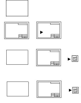
•Create an empty C-size Drawing Template.
•Import an AutoCAD drawing and save the drawing as a C-size Sheet Format.
•Create a C-ANSI-MM Drawing Template.
•Combine the empty Drawing Template and the Sheet Format.
•Create an empty A-size Drawing Template.
•Modify an existing SolidWorks A-size Sheet Format.
•Create an A-ANSI-MM Drawing Template.
•Combine the empty Drawing Template and the Sheet Format.
Empty C
Drawing
Template
C-SIZE-ANSI-MM-EMPTY.DRWDOT |
|
|
|
|
|
|
|
|
|
|
|
|
|
AutoCAD |
|
|
|
|
|
|
|
Sheet Format |
|||||
|
|
|
|
|
|
|
|
|
|
|
|
|
|
FORMAT-C-ACAD.DWG |
|
|
|
|
|
|
|
C-FORMAT.SLDDRT |
|||||
Empty C |
|
|
|
|
|
|
|
Sheet Format |
|||||
Drawing |
|
|
|
|
|
|
|
|
|
|
|
|
|
Template |
|
|
|
|
|
|
|
|
|
|
|
|
|
|
|
|
|
|
|
|
|
|
|
|
|
|
C-ANSI-MM.DRWDOT |
C-SIZE-ANSI-MM-EMPTY.DRWDOT |
|
|
|
|
|
|
|
C-FORMAT.SLDDRT |
|||||
Empty A |
|
|
|
|
|
|
|
Sheet Format |
|||||
Drawing |
|
|
|
|
|
|
|
|
|
|
|
|
|
Template |
|
|
|
|
|
|
|
|
|
|
|
A-ANSI-MM.DRWDOT |
|
|
|
|
|
|
|
|
|
|
|
|
|
|
|
A-SIZE-ANSI-MM-EMPTY.DRWDOT |
|
|
|
|
|
|
|
A-FORMAT.SLDDRT |
|||||
Conserve drawing time. Create a custom Drawing Template and Sheet Format. The Drawing Template and Sheet Format contain global drawing and detailing standards. Note: Dimensioning techniques are similar for non-ANSI dimension standards.
PAGE 1-4

Drawing and Detailing with SolidWorks 2001/2001Plus |
Drawing Template and Sheet Format |
SolidWorks Tools and Commands
The following SolidWorks tools and commands are utilized in this Project:
SolidWorks Tools and Commands
Drawing Template |
Tools, Options, |
Tools, Options, |
|
System Options |
Document Properties |
|
|
|
Standard Sheet Format |
Custom Sheet Format |
No Sheet Format |
|
|
|
Paper Size |
Sheet Setup |
Scale |
|
|
|
Drawing Options |
Display Modes |
Tangent Edge |
|
|
|
File Locations |
Line Styles and |
Detailing options |
|
Thickness |
|
|
|
|
Dimensioning Standard |
Font |
Arrows |
|
|
|
Line Font |
DXF/DWG Import |
Edit Sheet/Edit Sheet |
|
|
Format |
|
|
|
Note |
Link to Property |
Custom Property |
|
|
|
Additional information on SolidWorks tools and other commands are found in the On-Line Help.
PAGE 1-5
Drawing Template and Sheet Format |
Drawing and Detailing with SolidWorks 2001/2001Plus |
Engineering Drawing and Related Documentation Practices
Drawing Templates in this section are based upon the American Society of Mechanical Engineers ASME Y14 American National Standard for Engineering Drawing and Related Documentation Practices. These standards represent the drawing practices used by U.S. industry. The ASME Y14 practices supersede the American National Standards Institute ANSI standards. The ASME Y14 Engineering Drawing and Related Documentation Practices are published by The American Society of Mechanical Engineers, New York, NY. References to the current ASME Y14 standards are used with permission.
ASME Y14 |
American National Standard |
Revision of the Standard |
Standard Name |
Engineering Drawing and |
|
|
Related Documentation |
|
|
|
|
ASME Y14.100M- |
Engineering Drawing Practices |
DOD-STD-100 |
1998 |
|
|
|
|
|
ASME Y14.1-1995 |
Decimal Inch Drawing Sheet |
ANSI Y14.1 |
|
Size and Format |
|
|
|
|
ASME Y14.1M- |
Metric Drawing Sheet Size and |
ANSI Y14.1M |
1995 |
Format |
|
|
|
|
ASME Y14.24M |
Types and Applications of |
ANSI Y14.24M |
|
Engineering Drawings |
|
|
|
|
ASME Y14.2M |
Line Conventions and |
ANSI Y14.2M |
(Reaffirmed 1998) |
Lettering |
|
|
|
|
ASME Y14.3M- |
Multiview and Sectional View |
ANSI Y14.3 |
1994 |
Drawings |
|
|
|
|
ASME Y14.5M – |
Dimensioning and Tolerancing |
ANSI Y14.5-1982(R1988) |
1994(Reaffirmed |
|
|
1999) |
|
|
|
|
|
Only a portion of the ASME Y14 American National Standard for Engineering Drawing and Related Documentation Practices are presented in this book. Information presented in Projects 1 - 5 represent sample illustrations of a drawing, view and or dimension type. The ASME Y14 Standards Committee develops and maintains additional Drawing Standards. Members of these committees are from Industry, Department of Defense and Academia.
PAGE 1-6
Drawing and Detailing with SolidWorks 2001/2001Plus |
Drawing Template and Sheet Format |
Companies create their own drawing standards based upon one or more of the following:
•ASME Y14
•ISO or other International drawing standards
•Older ANSI standards
•Military standards
Of course there is also the “We’ve always done it this way” drawing standard or “Go ask the Drafting Supervisor” drawing standard.
PAGE 1-7
Drawing Template and Sheet Format |
Drawing and Detailing with SolidWorks 2001/2001Plus |
Drawing Template
The foundation of a SolidWorks drawing is the Drawing Template. Drawing size, drawing standards, company information, manufacturing and or assembly requirements, units and other properties are defined in the Drawing Template.
The Sheet Format is incorporated into the Drawing Themplate. The Sheet Format can contain border, title block and revision block information, company name and or logo information, Custom Properties and or SolidWorks Properties.
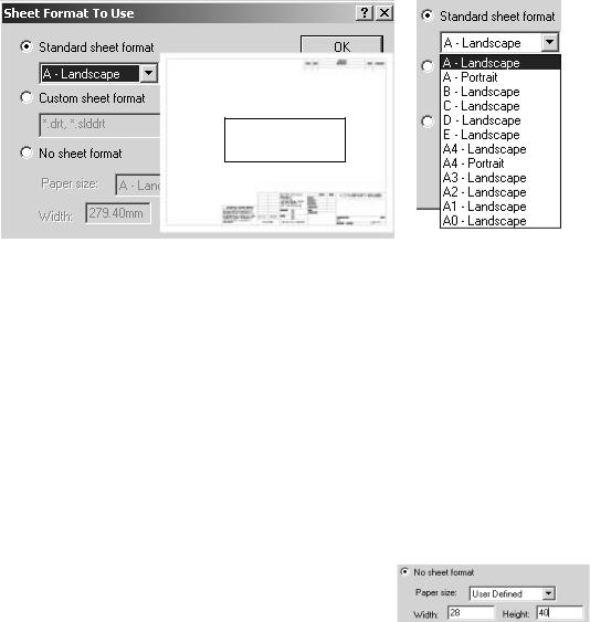
Create a custom Drawing Template. SolidWorks starts with a default Drawing Template. Select the No Sfheet Format. Create a custom Sheet Format from the default drawing template.
The default SolidWorks Standard Sheet Format is A-Landscape.
A-Landscape
Note: The ASME Y14.1-1995 Decimal Inch Drawing Sheet Size and Format and ASME Y14.1M-1995 Metric Drawing Sheet Size and format standard define the sheet size specification in inch and metric units respectively.
Drawing Size refers to the physical paper size used to create the drawing. The most common paper size in the U.S. is A size: (8.5in. x 11in.). The most common paper size internationally is A4 size: (210mm x 297mm).
The ASME Y14.1-1995 and ASME Y14.1M-1995 standards contain both a horizontal and vertical format for A and A4 size, respectively.
The corresponding SolidWorks format is Landscape for horizontal and Portrait for vertical.
Drawing sizes A through E are predefined in SolidWorks. Drawing sizes F, G, H, J & K are User Defined in the No Sheet Format drop
down list. Metric drawing sizes A4 through A0 are predefined in SolidWorks. Metric roll paper sizes are User Defined in the No Sheet Format drop down list.
PAGE 1-8
