

Drawing and detailing with SolidWorks
.pdfDrawing and Detailing with SolidWorks 2001/2001Plus |
Drawing Template and Sheet Format |
72)Combine Link Properties for the SHEET text. Click a start point in the upper left hand corner below the SHEET text. Click Note  from the Annotations toolbar.
Click No leaders. Click Link to Property  from the Text Format box. Select
SW-Current Sheet from the drop down list. Click OK. Enter the text OF. Click Link to Property  from the Text
Format box. Select SW-Total Sheets from the drop down list. The variable $PRP”SW-Sheet Format Size” is displayed in the Note text box. Display the
Sheet Format Size. Click OK. The Current Sheet value and Total Sheets value change as additional sheets are added to the drawing.
73)Create a Linked Property to SCALE. Click a start point in the upper left hand corner below the SCALE text. Click Note  from the Annotations toolbar. Click Link to Property
  from the Text
Format box. Select SW-Sheet Scale from the drop down list.
Click OK. The variable $PRP “SW-Sheet Scale” is displayed
in the Note text box. Click OK.
The Sheet Scale value changes to reflect the sheet scale properties in the drawing.
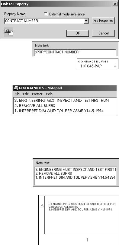
Your company has a policy that a contract number must be contained in the title block for all associated drawings in a project. Create a Custom Property named CONTRACT
NUMBER. Add it to the drawing title block. The Custom Property is contained in the Sheet Format.
74)Create a Custom Property for the CONTRACT NUMBER text. Click a start point in the upper left hand corner below the CONTRACT NUMBER text. Click Note  from the Annotations toolbar. Click No leaders. Click Link to Property
  from
from
the Text Format box.
75)Select the File Properties button. Click the Custom tab. Enter the
CONTRACT NUMBER for Name. Text is the default type. Click 101045-PAP for Value. Click Add. The Custom Property is displayed in the Properties text box. Click OK.
PAGE 1-39
Drawing Template and Sheet Format |
Drawing and Detailing with SolidWorks 2001/2001Plus |
76)Enter the
CONTRACT NUMBER in the Property Name text box. Click
OK.
77)The Note text
box displays: $PRP: “CONTRACT NUMBER”. Display 101045-PAP. Click OK.
78)Fit the drawing to the Graphics window. Press the f key.
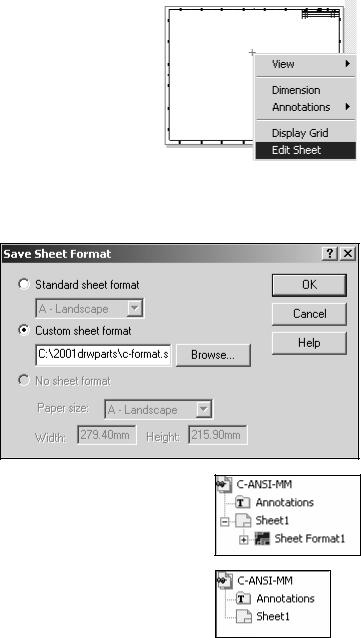
Conserve drawing time. Place general notes which are commonly used on a drawing in the Sheet Format. The
Engineering department stores general notes in a Notepad file, GENERALNOTES.TXT. General notes are usually located in a corner of a drawing.
79)Create general notes from a text file. Double-click on the Notepad file, GENERALNOTES.TXT. Highlight all text. Click Edit, Select All. Copy the text into the windows clipboard. Click Ctrl C.
80)Click a start point in the lower
left hand corner of the title block. Click Note  from the Annotations toolbar. Click inside the Note text box. Paste the three lines of text. Click
Ctrl V.
81)Display the general notes on the drawing. Click OK.
PAGE 1-40
Drawing and Detailing with SolidWorks 2001/2001Plus |
Drawing Template and Sheet Format |
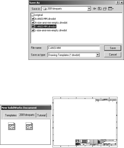
82)Return to the drawing sheet. Right-click in the
Graphics window. Click Edit Sheet. The drawing boarder is displayed in gray.
83)Fit the drawing to the Graphics window. Press the f key.
84)Click None from the Layer text box.
Note: Save your Sheet Format and Drawing Templates in the Edit Sheet mode. Views are
displayed when inserted into the drawing. Views cannot be displayed in the Edit Sheet Format mode. The None option is set for Layer and saved with the Drawing Template.
Save the Sheet Format.
85)Click File, Save Sheet Format. Select the Custom Sheet Format button. Click the Browse button. Select the C- FORMAT.slddrt sheet format from the 2001drwparts file folder. Click
OK.
Note: The Sheet Format1 icon is displayed in the FeatureManager. Delete the Sheet Format1 icon before saving the Drawing Template. The Sheet Format option is displayed when the New Drawing Template is selected.
For 2001 Plus: Press Ctrl Q to display the Sheet
Format1 icon in the FeatureManager.
PAGE 1-41
Drawing Template and Sheet Format |
Drawing and Detailing with SolidWorks 2001/2001Plus |
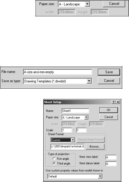
Create a new Drawing Template: C-ANSI-MM. Combine the Sheet Format and the empty Drawing Template.
Save the new Drawing template.
86)Click File,
SaveAs. Select
Drawing Templates for Save as type. Browse the 2001drwparts file folder. Enter
C-ANSI-MM.
87)Close all documents. Click
Windows, Close All.
88)Click No to the questions: “Save DRAW1 and Save DRAW2.”
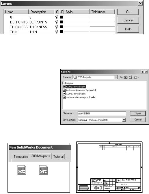
89)Verify the template. Click New. Click the 2001drwparts tab. Click the C-ANSI-MM template. Click OK.
C-SIZE-
C-ANSI-MM
ANSI-MM-
EMPTY
General Notes
PAGE 1-42
Drawing and Detailing with SolidWorks 2001/2001Plus |
Drawing Template and Sheet Format |
A - Size Drawing Template
Create an A size Drawing Template and an A size Sheet Format. Text size for an A-size drawing is the same as a C-size drawing. Create hthe A-size Drawing Template. Utilize the empty C-size Drawing Template. Create an A-ANSI-MM Drawing Template. Add an A-size Sheet Format.
Create a new A-size drawing template.
90)Create a new Drawing Template from an existing Drawing Template. Click
New. Select C-SIZE-ANSI-
MM-EMPTY. Click No Sheet Format. Select A-Landscape for Paper size. Click
OK. Note: The Document Properties set for the C-Size Drawing Template are copied to the A-size Drawing Template.
91)Fit the template to the Graphics window. Press the f key.
92)Save the A-size Drawing Template. Click File, Save As. Select Drawing Templates for Save as type. Browse to the 2001drwparts file folder. Enter
A-SIZE-ANSI-MM-EMPTY. Click the Save button.
Load the Custom A-size sheet format.
93)Right-click in the Graphics window. Click Properties. Click Custom for the Sheet Format. Browse and select
A-FORMAT.slddrt from the 2001drwparts file folder. Click OK.
Note: The A-FORMAT is created in inches. The A-SIZE-ANSI- MM-EMPTY Drawing Template is created in millimeters. The Drawing Template controls the units.
PAGE 1-43
Drawing Template and Sheet Format |
Drawing and Detailing with SolidWorks 2001/2001Plus |
The A-FORMAT geometry, text and dimensions are created on separate layers. The None option is the current Layer. A-FORMAT is displayed in Edit Sheet mode.
Create a new Drawing Template: A-ANSI-MM. Combine the Sheet Format and the empty Drawing Template.
Save the new Drawing template.
94)Click File, SaveAs. Select
Drawing Templates(*.drwdot) for Save as type. Browse the 2001drwparts file folder. Enter A-ANSI-MM.
95)Close all documents. Click
Windows, Close All.
96)Verify the template. Click New. Click the
2001drwparts tab. Click the
A-ANSI-MM template. Click OK.
A-SIZE-
A-ANSI-MM
ANSI-MM-
EMPTY
The A-ANSI-MM and C-ANSI-MM Drawing Templates and A-FORMAT and C-FORMAT Sheet Formats are use in the next Project. Create Drawing Templates for inch Document Properties in the Exercises at the end of this Project. Import other Sheet Formats into SolidWorks.
PAGE 1-44
Drawing and Detailing with SolidWorks 2001/2001Plus |
Drawing Template and Sheet Format |
Questions
1.Name the drawing options that are defined in the Drawing Template.
2.Name five drawing items that are contained in the Sheet Format.
3.Identify the paper dimensions for an A-size horizontal drawing.
4.Identify the paper dimensions for an A4 horizontal drawing.
5.The SolidWorks format Landscape corresponds to a______________ drawing format and Portrait corresponds to a_____________________ drawing format.
6.What Paper Size option do you select in order to define a custom paper width and height?
7.Identify the primary type of projection utilized on a drawing in the United States.
8.Describe the steps to display and modify the properties on a drawing sheet.
9.Identify the location of the stored System Options.
10.Name the three display modes for drawing views using SolidWorks 2001. Name the four display modes for drawing views using SolidWorks 2001Plus.
11.True or False. SolidWorks Line Font Types define all ASME Y14.2 type and style of lines.
12.Identify all Dimensioning standards options supported by SolidWorks.
13.Identify 10 drawing items that are contained in a title block.
14.SolidWorks Properties are saved with the __________________ Format.
PAGE 1-45
Drawing Template and Sheet Format |
Drawing and Detailing with SolidWorks 2001/2001Plus |
Exercises
Create Drawing Templates for both inch units and Metric units. ASME Y14.5M has different rules for Metric and English unit decimal display.
English decimal display:
A dimension value is less than 1 inch. No leading zero is displayed before the decimal point. See Table 1 for details.
Metric decimal display:
A dimension value is less than 1mm. A leading zero is displayed before the decimal point. See Table 1 for details.
General Tolerances are specified in the Title Block. Specify tolerances are applied to an individual dimension. A dimension is displayed to the same number of decimal places as its tolerance for inch Unilateral Tolerance. Select ANSI for the SolidWorks Dimensioning Standard. Select inch or metric for Drawing units.
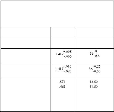
TABLE 1
TOLERANCE DISPLAY FOR INCH AND METRIC
DIMENSIONS (ASME Y14.5M)
DISPLAY INCH METRIC
Dimensions less than 1 |
.5 |
0.5 |
Unilateral Tolerance
Bilateral Tolerance
Limit Tolerance
PAGE 1-46
Drawing and Detailing with SolidWorks 2001/2001Plus |
Drawing Template and Sheet Format |
Exercise 1.1:
a)Create an A-size ANSI Drawing Template using inch units. Use an A-FORMAT Sheet Format.
b)Create a C-size ANSI Drawing Template using inch units. Use a C-FORMAT Sheet Format.
The ASME Y14.2M, Minimum letter height for Title Block is as shown in Table 2.
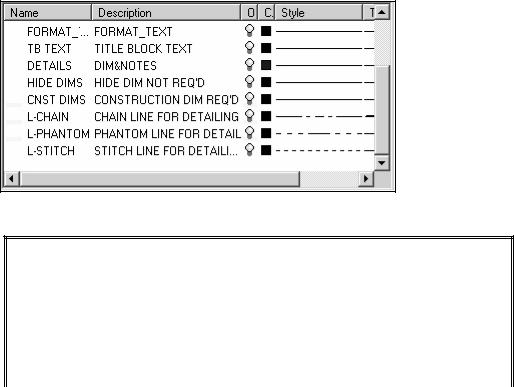
c) Create three New Layers named DETAILS, HIDE DIMS and CNST DIMS (Construction Dimensions). Create New Layers to display CHAIN, PHANTOM and STITCH lines.
TABLE 2
MINIMUM LETTER HEIGHT FOR TITLE BLOCK
(ASME Y14.2M)
Title Block Text |
Letter Height (inches) |
|
for A, B, C Drawing |
|
Size |
Drawing Title, Drawing Size, Cage |
.12 |
Code, Drawing Number, Revision |
|
Letter |
|
Section and view letters |
.24 |
Drawing block letters |
.10 |
All other characters |
.10 |
|
|
|
|
PAGE 1-47
Drawing Template and Sheet Format |
Drawing and Detailing with SolidWorks 2001/2001Plus |
Exercise 1.2:
Create an A4(horizontal) ISO Drawing Template. Use Document Properties to set the ISO dimension standard and millimeter units.
Exercise 1.3:
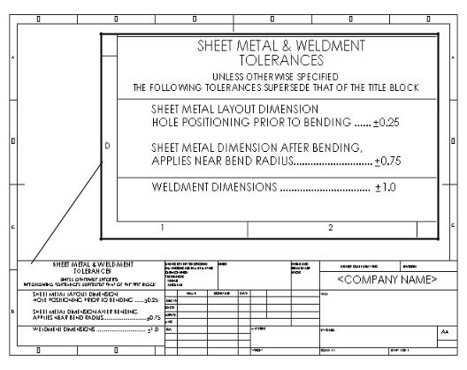
Modify the SolidWorks Drawing Template A4-ISO. Edit Sheet Format to include a new Sheet Metal & Weldment Tolerances box on the left hand side of the Sheet Format, Figure EX1.3.
Display sketched end points to create new lines for the Tolerance box. Click Tools, Options, System Options, Sketch. Check Display entity points. The endpoints are displayed for Sketch lines.
Figure EX1.3
SHEET METAL & WELDMENT TOLERANCES box courtesy of Ismeca, USA Inc. Vista, CA.
PAGE 1-48