

Drawing and detailing with SolidWorks
.pdfDrawing and Detailing with SolidWorks 2001/2001Plus |
Drawing Template and Sheet Format |
Set Drawing Properties.
13)Set Detailing Options. Click
Document Properties tab. Select Units from the left text box. Click Millimeters from the Linear Units drop down list. Enter 2 for Decimal places.
Note: Set units before entering values for Detailing options.
14)Click Detailing. Select ANSI from the Dimensioning standard drop down list. Detailing options are available depending upon the selected standard.
Drawing and option availabilities are affected by various Drawing Properties.
The Dimensioning standard options are: ISO, DIN, JIS, BSI, GOST and GB. Obtain additional drawing options through the On-Line Help.
Review the Detailing options function before entering their values.
Millimeter dimensioning and decimal inch dimensioning are the two types of units specified on engineering drawings. There are other dimension types specified for commercial commodities such as pipe sizes and lumber sizes.
Develop separate drawing templates for decimal inch units. Text height, arrows and line styles are defined with inch values according to the
ASME Y14.2-1992(R1998) Line Conventions and Lettering standard.
The Dual dimensions display check box shows dimensions in two types of units. Example: Select Dual dimensions display. Select the On top option. The primary unit display is 100mm. The secondary units display is [3.94] inches.
PAGE 1-19
Drawing Template and Sheet Format |
Drawing and Detailing with SolidWorks 2001/2001Plus |
The Fixed size weld symbols checkbox displays the size of the weld symbol. Scale according to the dimension font size.
The Display datums per 1982 checkbox shows the ANSI
Y14.5M-1982 datums.
The ASME Y14.5M-1994(R1999) datums are used in this text. 
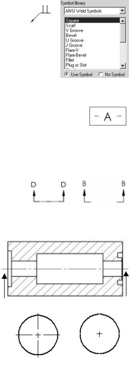
The ASME Y14.2M-1992(R1998) standard supports two display styles for the Cutting-plane line or Viewing-plane line. The default section line displays with a continuous Phantom line
type(D-D). Check the Alternate section display to allow the arrow ends to stop at the ends of the section cut(B-B).
The Centerline extension value controls the extension length beyond the section geometry. Set the extension length to 3mm.
Center marks specifies the default center mark size used with arcs and circles. Center marks are displayed with or without center mark lines. The center mark lines extend just beyond the circumference of the selected circle. Set the default center mark size to 0.5mm. Base the center mark size on the drawing size and scale.
PAGE 1-20

Drawing and Detailing with SolidWorks 2001/2001Plus |
Drawing Template and Sheet Format |
SolidWorks uses the term Witness lines. Witness lines
are Extension lines as defined in the ASME Y14.2M-1992(R1998) and
ASME Y14.5M1994(R1999) standard. A visible Gap exists between
the Extension line and the Visible line. The Extension line extends 3mm beyond the Dimension line. Set Gap to 1.5mm. Set the Extension to 3mm. Note: The values 1.5mm and 3mm are a guide. Base the Gap and Extension line on the drawing size and scale.
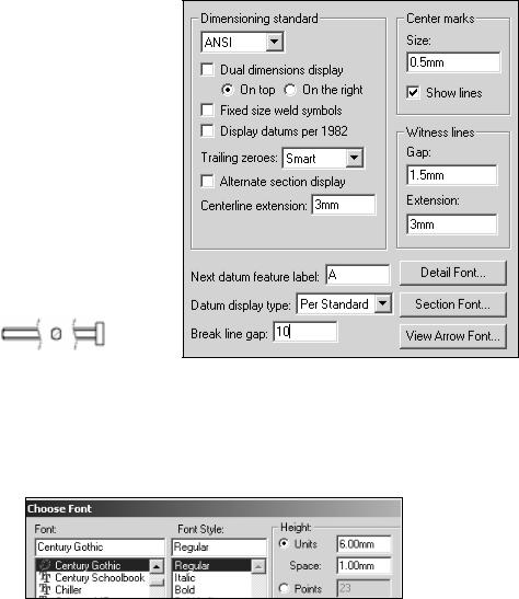
The Next datum feature label specifies the next upper case letter used for the Datum Feature Symbol. The default value is A. Successive labels are in alphabetical order.
The Datum display type Per Standard shows a filled triangular symbol on the Datum Feature.
The Break line gap specifies the size of the gap between the Broken view break lines. Set the Broken view break lines to 10mm.
10mm
The Detail Font button specifies the font type and
size used for the letter labels on the detail circles. Set the Detail font to Century Gothic. Set the size to 6mm.
The Section Font button specifies the font type and size used for the letter labels on the section lines. Set the Section font to Century Gothic. Set the size to 6mm.
The View Arrow Font button specifies the font type and size used for the letter labels on the view arrows. Set the View Arrow font to Century Gothic. Set the size to 6mm.
Set the values in SolidWorks to meet the ASME standard.
PAGE 1-21
Drawing Template and Sheet Format |
Drawing and Detailing with SolidWorks 2001/2001Plus |
Set Detail Options.
15)Enter 3mm for the Centerline extension.
16)Enter 0.5mm for the Center marks.
17)Modify the Witness lines (Extension line) values. Enter 1.5mm for Gap.
Enter 3mm for Extension.
18)Enter 10mm for the Break line gap. Note: There is no set value for the Break line gap. Increase the value to accommodate a revolved section.
2001Plus
19)Set the Detail Font. Click
the Detail Font button. Enter 6mm for text. Repeat for Section Font and View Arrow Font. Accept all other defaults from the Detailing text box.
20)Review the Dimension options. Click Dimensions from the left side of the Detailing text box.
PAGE 1-22
Drawing and Detailing with SolidWorks 2001/2001Plus |
Drawing Template and Sheet Format |
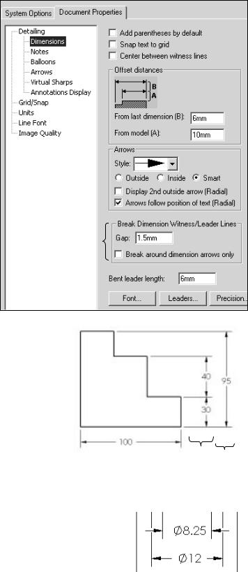
The Dimension options determine the display and position of text and extension lines. Reference dimensions require parentheses. Many features were created with symmetry and the dimension scheme must be redefined in the drawing. Uncheck the Add parentheses by default to save time. Parenthesis can be added to a dimension at anytime
through the Property
2001 Plus
option.
The ASME Y14.5M1994(R1999) standard set guidelines for dimension spacing. The space between the
first dimension line and the part outline should not be less than 10mm. The space between subsequent parallel dimension lines should not be less than 6mm. Spacing may be different depending upon drawing size and scale. Set the offset distance from the last dimension to 6mm. Set the offset distance from the model to 10mm.
Arrow heads can be opened or filled.
The ASME Y14.2M-1992(R1998) 10 6 standard recommends a solid filled
arrow.
The ASME Y14.5M-1994(R1999) standard states that crossing dimension lines should be avoided. When dimension lines cross, close to an arrowhead, the extension line (Witness line) must be broken.
PAGE 1-23
Drawing Template and Sheet Format |
Drawing and Detailing with SolidWorks 2001/2001Plus |
Drag the extension line above the arrowhead. Sketch a new line collinear with the
extension line below the arrowhead.
For 2001Plus: Set the Break Dimension Line Gap to 1.5mm. Uncheck the Break around the dimension arrows. Control individual breaks on dimensions for this project.
Leader lines are created with a small horizontal segment. This is |
|
called the Bent Leader line length. Set the Bent Leader line |
|
length to 6mm. |
6 |
|
|
Select the Font button to set the Dimension text height. All |
|
|
|
dimension text is set to 3mm. |
|
Set Dimensions options.
21)Uncheck the Add Parentheses by Default check box.
22)Set the Offset distances to 6mm and 10mm.
23)Set the Arrow style to Solid.
24)For 2001Plus: Enter 1.5mm for the Gap in the Break Dimension Witness/Leader Lines. Uncheck the Break around dimension arrows only.
25)Enter 6mm for the Bent leader length.
26)Click the Font button. Enter 3 for Units in the Height text box. Century Gothic is the default
Font. Click OK. |
2001Plus |
|
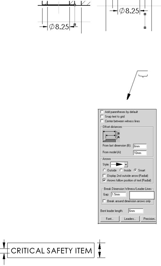
Note: Text positioned on the drawing, outside the Title block, are the same font and height as the Dimension font. There are exceptions to the rule. When a Note refers to a specific ASME Y14.100M-1998 Engineering Drawing Practices extended symbol. Example:
|
|
h is the text |
h |
2h |
height |
|
|
|
PAGE 1-24
Drawing and Detailing with SolidWorks 2001/2001Plus |
Drawing Template and Sheet Format |
Use Upper case letters unless lower case is required. Example: HCl – Hardness Critical Item requires a lower case “l”.
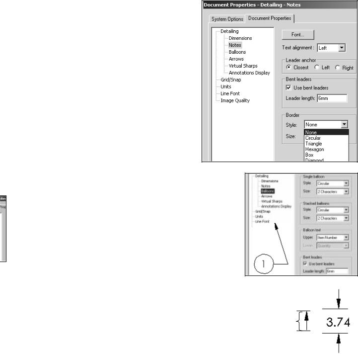
Modify Note Border Style to create boxes, circles, triangles and other shapes around the text. Modify the border height. Use the Size option.
Set Notes options.
27)Click Notes from the left side of the Detailing text box.
28)Click the Font button. Enter 3 for Units in the Height text box. Century Gothic is the default Font. Click OK.
29)Check Use Bent leaders. Enter 6mm for the Leader Length.
Balloon callouts label the parts in an assembly and relate them to the item numbers in the Bill of Materials.
Set the drawing Balloon Properties.
30)Click Balloons from the left side of the Detailing text box.
31)For 2001Plus: Check Use bent leaders. Enter 6mm for the Leader length.
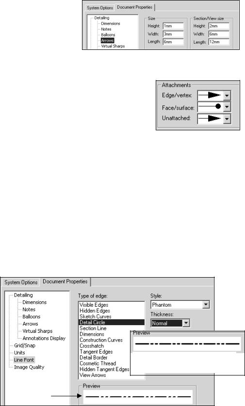
Set Arrows Properties according to the ASME Y14.2M-1992(R1998) standard at a 3:1 ratio for Width:Height. The Length value is the overall length of the arrow from the tip of the head to the end of the tail. The Length is displayed when the dimension text is flipped to the inside. A Solid filled arrowhead is the preferred arrow type for dimension lines. Arrow sizes change due to drawing size and scale. The ratio of width to height remains at 3:1.
Arrow
Length
PAGE 1-25
Drawing Template and Sheet Format |
Drawing and Detailing with SolidWorks 2001/2001Plus |
Set Arrow Properties.
32)Click the Arrows entry on the left side of the Detailing text box. The Detailing - Arrows dialog box is displayed. Enter 1 for the arrow Height in the Size text box. Enter
3 for the arrow Width. Enter 6 for the arrow Length. Set the arrow style. Under the Section/View size, Enter 2 for Height, 6 for Width and 12 for Length.
33)Click the solid filled arrowhead from the Edge/vertex list box. Click the solid filled dot from the Face/surface list box.
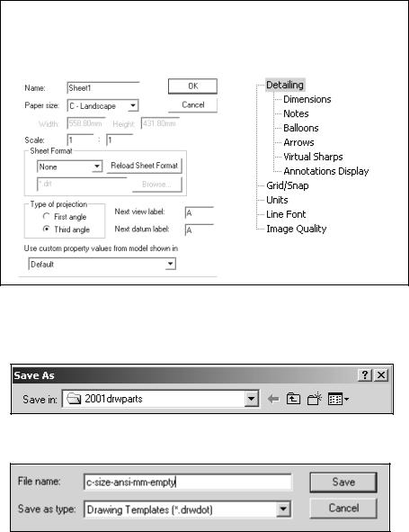
The Line Font determines the Style and Thickness for a particular type of edge in a drawing. Modify the Type of edge, Style and
Thickness to reflect the ASME Y14.2M-1992(R1998) standard.
Recall that two line weights are defined in the ASME Y14.2M-1992(R1998) standard; namely 0.3mm and 0.6mm. Thin Thickness is 0.3mm. Thick (Normal) Thickness is 0.6mm. Review line weights as defined in the File, PageSetup or in File, Print, System Options for your particular printer/plotter.
SolidWorks controls the line weight display in the Graphics window. Use Thin Thickness and Normal Thickness in the Graphics window. Change all Thick Thickness settings to Normal Thickness. Change Detail Circle Style to Phantom. Change View Arrows Style to Phantom.
Set Line Font Properties.
34)Click Line Font from the left side of the Detailing text box. Click Detail Circle for the Type of edge. Select Phantom for Style. Select Normal for Thickness.
Thick Thickness is too wide for Graphics window display. Change to Normal Thickness
Normal Thickness
PAGE 1-26
Drawing and Detailing with SolidWorks 2001/2001Plus |
Drawing Template and Sheet Format |
35)Click Section line for the Type of edge. Click Normal for Thickness.
36)Click View Arrows for the Type of edge. Click Solid for Style. Click Normal for Thickness.
37)Exit Drawing Properties. Click OK.
38)Click the Graphics window. The drawing border is displayed in green.
The empty Drawing Template contains no geometry. The empty Drawing Template contains the Document Properties and the Sheet Properties: Sheet name, Paper size, No Sheet Format and Third Angle Projection.
Empty Drawing Template
Sheet Properties |
Document Properties |
|
|
|
|
|
|
|
|
|
|
39)Save the empty Drawing Template. Click File, Save As. Select Drawing Templates(*.drwdot) from the Save as Type list. Select the Browse button. Select the 2001drwparts for the Save in file folder.
40) Enter C-SIZE-ANSI-MM-EMPTY for the File name. Click the Save button.
PAGE 1-27
Drawing Template and Sheet Format |
Drawing and Detailing with SolidWorks 2001/2001Plus |
Sheet Format
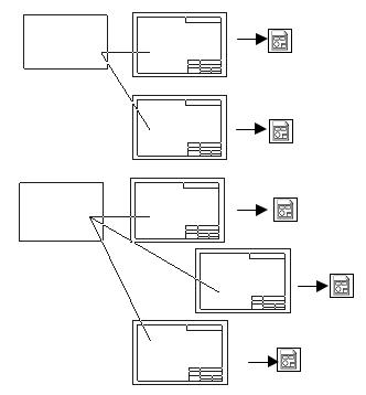
Customize drawing Sheet Formats to create and match your company’s drawing standards.
A customer requests a new product. The engineer designs the product in one location, the company produces the product in a second location and the field engineer supports the customer in a third location. The ASME Y14.24M standard describes various types of drawings.
Empty |
Custom |
Custom |
Drawing |
Sheet |
Drawing |
Template |
Format |
Template |
ANSI |
A Custom |
|
|
||
|
Properties |
|
|
B Custom |
|
|
Properties |
|
ISO |
MACHINE |
|
PARTS |
||
|
PLASTIC
PARTS
Example: Engineering produces detailed and
assembly drawings. The
drawings are used for machined, plastic and sheet metal parts that contain specific tolerances and notes used in fabrication. Manufacthuring adds vendor item drawings with tables and notes. Field Service requires installation drawings that are provided to the customer. Sheet formats are created to support various standards and drawing types.
There are numerous ways to create a custom Sheet Format:
•Open a SolidWorks, AutoCAD, Pro/ENGINEER or other CAD software saved as file type, “.dwg”. Save the “.dwg” file as a Sheet Format.
•Right-click in the Graphics window. Select Edit Sheet Format. Create drawing borders, title block, notes and zone locations for each drawing size. Save each drawing format.
•Right-click Properties in the Graphics window. Select Properties. Select Custom from the Sheet Format drop down list. Browse to select an existing Sheet Format.
•Add an OLE supported Sheet Format such as a bitmap file of the title block and notes. Use the Insert, Object command.
PAGE 1-28