

Drawing and detailing with SolidWorks
.pdfDrawing and Detailing with SolidWorks 2001/2001Plus |
Drawing Template and Sheet Format |
The ASME Y14.1-1995 Decimal Inch Drawing Sheet Size standard are as follows:
Drawing Size |
Size in inches |
|
“Physical Paper” |
Vertical |
Horizontal |
|
|
|
A horizontal (landscape) |
8.5 |
11.0 |
|
|
|
A vertical (portrait) |
11.0 |
8.5 |
|
|
|
B |
11.0 |
17.0 |
|
|
|
C |
17.0 |
22.0 |
|
|
|
D |
22.0 |
34.0 |
|
|
|
E |
34.0 |
44.0 |
|
|
|
F |
28.0 |
40.0 |
|
|
|
G, H, J and K apply to roll |
|
|
sizes, User Defined |
|
|
|
|
|
The ASME Y14.1M-1995 Metric Drawing Sheet Sizes standard are as
follows:
Drawing Size |
Size in Millimeters |
|
“Physical Paper” |
Vertical |
Horizontal |
|
|
|
A0 |
841 |
1189 |
|
|
|
A1 |
594 |
841 |
|
|
|
A2 |
420 |
594 |
|
|
|
A3 |
297 |
420 |
|
|
|
A4 horizontal (landscape) |
210 |
297 |
|
|
|
A4 vertical (portrait) |
297 |
210 |
|
|
|
Caution should be used when sending electronic drawings between U.S. and International colleagues. Drawing paper sizes vary.
PAGE 1-9

Drawing Template and Sheet Format |
Drawing and Detailing with SolidWorks 2001/2001Plus |
Example: An A-size (11in. x 8.5in.) drawing (280mm x 216mm) does not fit a A4 metric drawing (297mm x 210mm). Use a larger paper size or scale the drawing using the printer setup options.
Note: The Sheet Formats, parts and assemblies required to complete the projects in
Drawing and Detailing with SolidWorks 2001/2001Plus are only available on-line at: www.schroff1.com.
Download the 2001drwparts file folder from www.schroff1.com.
1)Enter www.schroff1.com from your web browser.
2)Click the hypertext: Drawing and Detailing with SolidWorks 2001/2001Plus.
The file folder, 2001drwparts is downloaded.
Start a SolidWorks session.
3)Click Start on the Windows Taskbar,  . Click Programs. Click the
SolidWorks  folder.
4)Click the SolidWorks  application. The SolidWorks program window opens.
Create an Empty C-size Drawing Template.
5)Click New  . Click Drawing. Click OK.
6)Select No Sheet Format from the Sheet format to Use
dialog box. Select
C-Landscape from the Paper size drop down list. Click OK.
The C-Landscape Drawing Template is displayed in a new Graphics window. The sheet border defines the
C drawing size, (22in. x 17in.). Landscape indicates
that the larger dimension is along the horizontal. h Landscape Portrait Portrait indicates that the larger dimension is along the
vertical. Note: Portrait is only an option for A and A4 paper size.
PAGE 1-10
Drawing and Detailing with SolidWorks 2001/2001Plus |
Drawing Template and Sheet Format |
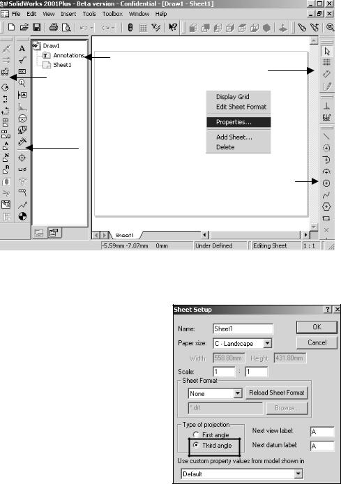
The Drawing toolbar and Annotations toolbar are displayed left of the Graphics window. The FeatureManager is displayed to the left of the Graphics window. The Sketch and Sketch Tools toolbars are displayed to the right of the Graphics window.
Empty
Drawing
Template –
No Sheet
Format
7)Right-click in the Graphics window. Click Properties. The Sheet Setup Properties are displayed.
Set the Sheet Properties.
8)The default sheet Name is Sheet1. The Paper size is C-Landscape. A drawing can contain one or more sheets. Sheet scale controls the default scale. The default Sheet Scale is 1:1. Click Third Angle for Type of Projection. Click OK.
The Automatic scaling of 3 view option, scales the three standard views to fit the drawing sheet. Examples of Third Angle and First Angle projection are developed in Project 2. Third Angle
projection is primarily used in the United States. For company’s supporting a First Angle projection scheme, views in Project 2 are placed in different locations.
PAGE 1-11
Drawing Template and Sheet Format |
Drawing and Detailing with SolidWorks 2001/2001Plus |
System Options and Document Properties
System Options are stored in the registry of the computer. System Options is not part of the document. Changes to the System Options affect all current and future documents.
ANSI or ISO Dimension Standard, Units and other Properties are set in Document Properties. Document Properties apply only to the current document. When you save the current document as a template, the current parameters are stored with the template. New documents that utilize the same template contain these set parameters.
Conserve drawing time. Set the System Options and Document Properties before you begin a drawing.
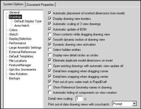
Set System Options.
9)Set the Drawings options used in this text. Click Tools, Options, System Options, Drawings. Note: Drawing options can be turned on or off.
PAGE 1-12
Drawing and Detailing with SolidWorks 2001/2001Plus |
Drawing Template and Sheet Format |
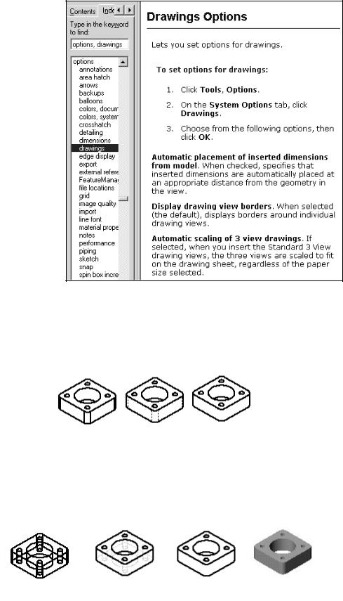
Drawings Options are available from the On-Line help.
10)Click the Help button in the System Options dialog box. The Drawings Options help is displayed. Review each Drawing option. Drag the Scroll bar downward.
Minimize the Help window.
On-line Help is a great resource for additional
information on SolidWorks functions. Help is accessible through the Help button, F1 key, Main menu and “?” icon.
Review the display modes settings for a new drawing.
Review the tangent edges setting for a new drawing.
Displayed modes and tangent edge settings can be changed in the individual drawing view.
PAGE 1-13
Drawing Template and Sheet Format |
Drawing and Detailing with SolidWorks 2001/2001Plus |
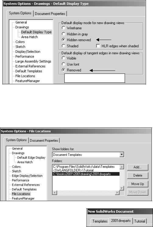
11)Set the Default Display Type. Click Default Display Type below the Drawings text. Click Hidden removed for the Default display mode for new drawing views. Click Removed for the Default display of tangent edges in the new drawing views.
Click OK.
Shaded Option (2001 Plus)
Set the File Locations to the 2001drwparts Folder for Drawing Templates.
Set File Locations for Drawing Templates.
12)Click File Locations from the System Options tab. Select Drawing Templates from the Show Folders for Drop down list. Click Add button. Browse. Select the 2001drwparts folder that you downloaded from www.Schroff1.com. Click OK.
Note: The 2001drawparts tab appears in the New SolidWorks Drawing dialog box. The Drawing Templates that you create will be saved to the 2001drawparts file folder.
PAGE 1-14
Drawing and Detailing with SolidWorks 2001/2001Plus |
Drawing Template and Sheet Format |
The Drawing Properties Detailing options provide the ability to address: dimensioning standards, text style, center marks, witness lines, arrow styles, tolerance and precision. Drawing Properties are stored with the Drawing Template.
There are numerous text styles and sizes available in SolidWorks. Companies develop drawing format standards and use specific text height for Metric and English drawings. The ASME Y14.2M-1992(R1998) standard lists the lettering, arrowhead and line conventions and lettering conventions for engineering drawings and related documentation practices. Examples:
•Font: Utilize a single stroke, gothic lettering in all upper case letters. Use a single font. Century Gothic is the default SolidWorks font. Create a test page to insure that both Windows and your particular Printer/Plotter drivers support the selected font.
•Minimum letter height will vary depending upon usage on a drawing:
oMinimum letter height used for drawing title, drawing size, CAGE Code, drawing number and revision letter positioned inside the Title block is .12in. (3mm) for A, B and C inch sizes and A2, A3 and A4 metric drawing sizes: Text height is .24in. (6mm) for D and E inch drawing sizes and A0, A1 metric drawing sizes.
oMinimum letter height for Section views, Zone letters and numerals is
.24in. (6mm) for all drawing sizes. Set Text size for Section, Detail and View font to 6mm.
oMinimum letter height for drawing block headings is .10in. (2.5mm) for all drawing sizes.
oMinimum letter height for all other characters is .12in. (3mm) for all drawing sizes. Set Text size for Dimension and Note Font to 3mm.
•Arrowheads: Utilize solid filled single style arrowhead, with a 3:1 ratio of arrow length to arrow width. The arrowhead width is proportionate to the line thickness. The Dimension line thickness is 0.3mm. In this project, the arrow length is 3mm. Arrow width is 1mm. SolidWorks defines arrow size with three options: Height, Width and Length. Height corresponds to arrow width. Width corresponds to arrow length. Length corresponds to the distance from the tip of the arrow to the end of the tail.
•The Section line thickness is 0.6mm. The arrow length is 6mm. The arrow width is 2mm.
•Line Widths: The ASME Y14.2M-1992(R1998) standard recommends two line widths with a 2:1 ratio. The minimum width of a thin line is 0.3mm. The minimum width of a thick, “normal” line is 0.6mm. Note: A single width
PAGE 1-15
Drawing Template and Sheet Format |
Drawing and Detailing with SolidWorks 2001/2001Plus |
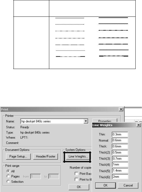
line is acceptable on CAD drawings. Two line widths are used in this Project; Thin: 0.3mm and Normal: 0.6mm. Apply Line Styles in the Line Font Document Properties. Line Font determines the appearance of a line in the Graphics window. SolidWorks styles utilized in this Project are as follows:
SolidWorks |
Thin (0.3mm) |
Normal (0.6mm) |
Line Style |
|
|
Solid
Dashed
Phantom
Chain
Center
Stitch
Thin/Thick Chain
Various printers/plotters allow variable Line Weight settings. Example: Thin (0.3mm), Normal (0.6mm) and Thick (0.6mm). Refer the printer/plotter owner’s manual for Line Weight setting.
Line Font: The ASME Y14.2M-1992(R1998) standard address the type and style of lines used on engineering drawings. Combine different styles and use drawing Layers to achieve the following types of lines:
PAGE 1-16
Drawing and Detailing with SolidWorks 2001/2001Plus Drawing Template and Sheet Format
ASME Y14.2- |
SolidWorks |
Style |
Thickness |
|||||||||||||
1992(R1998) |
Line Font |
|
|
|||||||||||||
TYPE of LINE |
Type of Edge |
|
|
|||||||||||||
and an example |
|
|
|
|
|
|
|
|
|
|
|
|
|
|
|
|
|
|
|
|
|
|
|
|
|
|
|
|
|
|
|
|
|
Visible line displays |
Visible Edge |
Solid |
Thick “Normal” |
|||||||||||||
the visible edges or |
|
|
|
|
|
|
|
|
|
|
|
|
|
|
|
|
contours of a part. |
|
|
|
|
|
|
|
|
|
|
|
|
|
|
|
|
|
|
|
|
|
|
|
|
|
|
|
|
|
|
|
|
|
Hidden line displays |
Hidden Edge |
Dashed |
Thin |
|||||||||||||
the hidden edges or |
|
|
|
|
|
|
|
|
|
|
|
|
|
|
|
|
contours of a part. |
|
|
|
|
|
|
|
|
|
|
|
|
|
|
|
|
|
|
|
|
|
|
|
|
|
|
|
|
|
|
|
|
|
Section lining displays |
Crosshatch |
Solid |
Thin |
|||||||||||||
the cut surface of a |
|
|
|
|
|
|
|
|
|
|
|
|
|
|
|
|
part/assembly in a |
|
|
|
|
|
|
|
|
|
|
|
|
|
|
|
Different Hatch |
|
|
|
|
|
|
|
|
|
|
|
|
|
|
|
||
section view. |
|
|
|
|
|
|
|
|
|
|
|
|
|
|
|
patterns relate to |
|
|
|
|
|
|
|
|
|
|
|
|
|
|
|
|
different materials |
|
|
|
|
|
|
|
|
|
|
|
|
|
|
|
|
|
Center line displays |
Construction |
Center |
Thin |
|||||||||||||
the axes of center |
Curves |
|
|
|||||||||||||
planes of symmetrical |
|
|
|
|
|
|
|
|
|
|
|
|
|
|
|
|
parts/features. |
|
|
|
|
|
|
|
|
|
|
|
|
|
|
|
|
|
|
|
|
|
|
|
|
|
|
|
|
|
|
|
|
|
Symmetry line |
|
|
|
|
|
|
|
|
|
|
|
|
|
|
|
Sketch Thin Center |
displays an axis of |
|
|
|
|
|
|
|
|
|
|
|
|
|
|
|
Line and Thick |
|
|
|
|
|
|
|
|
|
|
|
|
|
|
|
||
symmetry for a partial |
|
|
|
|
|
|
|
|
|
|
|
|
|
|
|
Visible lines on |
view. |
|
|
|
|
|
|
|
|
|
|
|
|
|
|
|
drawing Layer . |
|
|
|
|
|
|
|
|
|
|
|
|
|
|
|
|
|
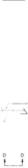
Dimension |
Dimensions |
Solid |
Thin |
|||||||||||||
lines/Extension |
|
|
|
|
|
|
|
|
|
|
|
|
|
|
|
|
lines/Leader lines |
|
|
|
|
|
|
|
|
|
|
|
|
|
|
|
|
|
|
|
|
|
|
|
|
|
|
|
|
|
|
|
|
|
combine to dimension |
|
|
|
Extension Line |
|
|
||||||||||
drawings. |
|
|
|
|
|
|||||||||||
|
|
|
Leader Line |
|
|
|||||||||||
|
|
|
|
|
|
|||||||||||
|
|
|
|
|
|
|
|
|
|
|
|
|
|
|
|
|
Cutting plane line or |
Section Line |
Phantom |
Thick |
|||||||||||||
Viewing plane line |
|
|
|
|
|
|
|
|
|
|
|
|
|
|
|
|
display the location of |
View Arrows |
Solid |
Thick, “Normal” |
|||||||||||||
a cutting plane for |
|
|
|
|
|
|
|
|
|
|
|
|
|
|
|
|
sectional views and |
|
|
|
|
|
|
|
|
|
|
|
|
|
|
|
|
the viewing position |
|
|
|
|
|
|
|
|
|
|
|
|
|
|
|
|
for removed views. |
|
|
|
|
|
|
|
|
|
|
|
|
|
|
|
|
|
|
|
|
|
|
|
|
|
|
|
|
|
|
|
|
|
PAGE 1-17
Drawing Template and Sheet Format |
Drawing and Detailing with SolidWorks 2001/2001Plus |
ASME Y14.2- |
SolidWorks Line |
Style |
Thickness |
1992(R1998) |
Font Type of Edge |
|
|
TYPE of LINE |
|
|
|
and an example |
|
|
|
|
|
|
|
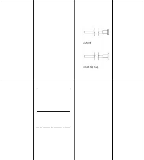
Break line displays |
|
|
Broken view |
an incomplete |
|
|
|
view. |
|
|
Use Curved for |
|
|
|
Short Breaks |
Short Breaks |
|
|
|
|
|
|
Use Small Zig |
Long Breaks |
|
|
Zag for Long |
|
|
|
Breaks |
Phantom line |
Sketch Thin |
displays alternative |
Phantom Line on |
position of moving |
drawing Layer |
parts. |
|
|
|
Stitch line displays |
Sketch Thin |
a sewing or |
Stitch Line on |
stitching process. |
drawing Layer |
|
|
Chain line displays |
Sketch Thick |
a surface that |
Chain Line on |
requires more |
drawing Layer |
consideration or |
|
the location of a |
|
projected tolerance |
|
zone. |
|
Note: The following lines are not predefined in SolidWorks: Symmetry line, Phantom line, Stitch line and Chain line. The line style and thickness for the above line types are defined on a separate drawing layer.
PAGE 1-18