

CY7C68013
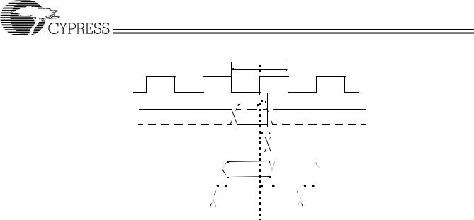
9.6Slave FIFO Synchronous Read
tIFCLK
IFCLK
tSRD 
 tRDH
tRDH
SLRD
|
|
|
|
|
|
|
|
|
|
|
|
|
|
|
|
|
|
|
|
|
|
|
|
|
|
|
|
|
|
|
|
|
|
|
|
|
|
|
|
|
|
|
|
|
|
tXFLG |
|
|
|
|
|
|
|
|
|
|
|
|
|
|
|
|
|
|
|
|
|
|
|
|
|||||
|
FLAGS |
|
|
|
|
|
|
|
|
|
|
|
|
|
|
|
|
|
|
|
|
|
|
|
|
|
|
|
|
|
|
|
|
|
|
|
|
|
|
|
|
|
|
|
|
|
|
|
|
|
|
|
|||||||||||||||||||||||
|
|
|
|
|
|
|
|
|
|
|
|
|
|
|
|
|
|
|
|
|
|
|
|
|
|
|
|
|
|
|
|
|
|
|
|
|
|
|
|
|
|
|
|
|
|
|
|
|
|
|
|
|
|
|
|
|
|
|
|
|
|
|
|
|
|
|
|
|
|
|
|
|
|
|
|
|
|
|
|
|
|
|
|
|
|
|
|
|
|
|
|
|
|
|
|
|
|
|
|
|
|
|
|
|
|
|
|
|
|
|
|
|
|
|
|
|
|
|
|
|
|
|
|
|
|
|
|
|
|
|
|
|
|
|
|
|
|
|
|
|
|
|
|
|
|
|
|
|
|||
|
DATA |
|
|
|
|
|
|
|
|
|
|
|
|
|
|
|
|
|
|
|
|
|
|
|
|
|
|
|
|
N |
|
|
|
|
N+1 |
|
|
|
|
|
|
|
|
|
|
|
|
|
|
|
|
|
|
|
|
|
|
|
|
||||||||||||||||
|
|
|
|
|
|
|
|
|
|
|
|
|
|
|
|
|
|
|
|
|
|
|
|
|
|
|
|
|
|
|
|
|
|
|
|
|
|
|
|
|
|
|
|
|
|
|
|
|
|
|
|
||||||||||||||||||||||||
|
|
|
|
|
|
|
|
|
|
|
|
|
|
|
|
|
|
tOEon |
|
|
|
|
|
|
|
|
|
|
|
|
|
|
|
|
|
|
|
|
tXFD |
|
|
|
|
|
|
tOEoff |
|
|
|
||||||||||||||||||||||||||
|
|
|
|
|
|
|
|
|
|
|
|
|
|
|
|
|
|
|
|
|
|
|
|
|
|
|
|
|
|
|
|
||||||||||||||||||||||||||||||||||||||||||||
|
SLOE |
|
|
|
|
|
|
|
|
|
|
|
|
|
|
|
|
|
|
|
|
|
|
|
|
|
|
|
|
|
|
|
|
|
|
|
|
|
|
|
|
|
|
|
|
|
|
|
|
|
|
|
|
|
|||||||||||||||||||||
|
|
|
|
|
|
|
|
|
|
|
|
|
|
|
|
|
|
|
|
|
|
|
|
|
|
|
|
|
|
|
|
|
|
|
|
|
|
|
|
|
|
|
|
|
|
|
|
|
|
|
|
|
|
|
|
|
|
|
|
|
|
|
|
|
|
|
|||||||||
|
Figure 9-5. Slave FIFO Synchronous Read Timing Diagram[13] |
|
|
|
|||||||||||||||||||||||||||||||||||||||||||||||||||||||||||||||||||||||
Table 9-5. Slave FIFO Synchronous Read Parameters with Internally Sourced IFCLK[15] |
|
|
|
||||||||||||||||||||||||||||||||||||||||||||||||||||||||||||||||||||||||
Parameter |
|
|
|
|
|
|
Description |
|
|
|
|
|
|
|
|
|
|
|
|
|
|
|
|
|
|
|
|
|
|
|
|
|
|
|
|
|
Min. |
|
|
|
|
|
|
|
Max. |
Unit |
|||||||||||||||||||||||||||||
|
|
|
|
|
|
|
|
|
|
|
|
|
|
|
|
|
|
|
|
|
|
|
|
|
|
|
|
|
|
|
|
|
|
|
|
|
|
|
|
|
|
|
|
|
|
|
|
|
|
|
|
|
|
|
|
|
|
|
|
|
|
|
|
|
|
|
|
|
|
|
|
|
|
|
|
tIFCLK |
IFCLK Period |
|
|
|
|
|
|
|
|
|
|
|
|
|
|
|
|
|
|
|
|
|
|
|
|
|
|
20.83 |
|
|
|
|
|
|
|
|
|
|
|
ns |
|||||||||||||||||||||||||||||||||||
tSRD |
SLRD to Clock Set-up Time |
|
|
|
|
|
|
|
|
|
|
|
|
|
|
|
|
|
|
|
|
|
|
|
|
|
|
18.7 |
|
|
|
|
|
|
|
|
|
|
|
|
ns |
||||||||||||||||||||||||||||||||||
tRDH |
Clock to SLRD Hold Time |
|
|
|
|
|
|
|
|
|
|
|
|
|
|
|
|
|
|
|
|
|
|
|
|
|
|
0 |
|
|
|
|
|
|
|
|
|
|
|
|
|
ns |
|||||||||||||||||||||||||||||||||
tOEon |
SLOE Turn-on to FIFO Data Valid |
|
|
|
|
|
|
|
|
|
|
|
|
|
|
|
|
|
|
|
|
|
|
|
|
|
|
|
|
|
|
|
|
|
|
|
|
|
|
|
|
|
|
|
|
|
|
|
10.5 |
ns |
|||||||||||||||||||||||||
tOEoff |
SLOE Turn-off to FIFO Data Hold |
|
|
|
|
|
|
|
|
|
|
|
|
|
|
|
|
|
|
|
|
|
|
|
|
|
|
|
|
|
|
|
|
|
|
|
|
|
|
|
|
|
|
|
|
|
|
|
10.5 |
ns |
|||||||||||||||||||||||||
tXFLG |
Clock to FLAGS Output Propagation Delay |
|
|
|
|
|
|
|
|
|
|
|
|
|
|
|
|
|
|
|
|
|
|
|
|
|
|
|
|
|
9.5 |
ns |
|||||||||||||||||||||||||||||||||||||||||||
tXFD |
Clock to FIFO Data Output Propagation Delay |
|
|
|
|
|
|
|
|
|
|
|
|
|
|
|
|
|
|
|
|
|
|
|
|
|
|
|
|
|
11 |
ns |
|||||||||||||||||||||||||||||||||||||||||||
Table 9-6. Slave FIFO Synchronous Read Parameters with Externally Sourced IFCLK[15] |
|
|
|
||||||||||||||||||||||||||||||||||||||||||||||||||||||||||||||||||||||||
Parameter |
|
|
|
|
|
|
Description |
|
|
|
|
|
|
|
|
|
|
|
|
|
|
|
|
|
|
|
|
|
|
|
|
|
|
|
|
|
Min. |
|
|
|
|
|
|
|
Max. |
Unit |
|||||||||||||||||||||||||||||
|
|
|
|
|
|
|
|
|
|
|
|
|
|
|
|
|
|
|
|
|
|
|
|
|
|
|
|
|
|
|
|
|
|
|
|
|
|
|
|
|
|
|
|
|
|
|
|
|
|
|
|
|
|
|
|
|
|
|
|
|
|
|
|
|
|
|
|
|
|
|
|
|
|
|
|
tIFCLK |
IFCLK Period |
|
|
|
|
|
|
|
|
|
|
|
|
|
|
|
|
|
|
|
|
|
|
|
|
|
|
20.83 |
|
|
|
|
|
|
|
|
|
200 |
ns |
||||||||||||||||||||||||||||||||||||
tSRD |
SLRD to Clock Set-up Time |
|
|
|
|
|
|
|
|
|
|
|
|
|
|
|
|
|
|
|
|
|
|
|
|
|
|
12.7 |
|
|
|
|
|
|
|
|
|
|
|
|
ns |
||||||||||||||||||||||||||||||||||
tRDH |
Clock to SLRD Hold Time |
|
|
|
|
|
|
|
|
|
|
|
|
|
|
|
|
|
|
|
|
|
|
|
|
|
|
3.7 |
|
|
|
|
|
|
|
|
|
|
|
|
ns |
||||||||||||||||||||||||||||||||||
tOEon |
SLOE Turn-on to FIFO Data Valid |
|
|
|
|
|
|
|
|
|
|
|
|
|
|
|
|
|
|
|
|
|
|
|
|
|
|
|
|
|
|
|
|
|
|
|
|
|
|
|
|
|
|
|
|
|
|
|
10.5 |
ns |
|||||||||||||||||||||||||
tOEoff |
SLOE Turn-off to FIFO Data Hold |
|
|
|
|
|
|
|
|
|
|
|
|
|
|
|
|
|
|
|
|
|
|
|
|
|
|
|
|
|
|
|
|
|
|
|
|
|
|
|
|
|
|
|
|
|
|
|
10.5 |
ns |
|||||||||||||||||||||||||
tXFLG |
Clock to FLAGS Output Propagation Delay |
|
|
|
|
|
|
|
|
|
|
|
|
|
|
|
|
|
|
|
|
|
|
|
|
|
|
|
|
|
13.5 |
ns |
|||||||||||||||||||||||||||||||||||||||||||
tXFD |
Clock to FIFO Data Output Propagation Delay |
|
|
|
|
|
|
|
|
|
|
|
|
|
|
|
|
|
|
|
|
|
|
|
|
|
|
|
|
|
15 |
ns |
|||||||||||||||||||||||||||||||||||||||||||
Document #: 38-08012 Rev. *F |
Page 34 of 48 |
CY7C68013
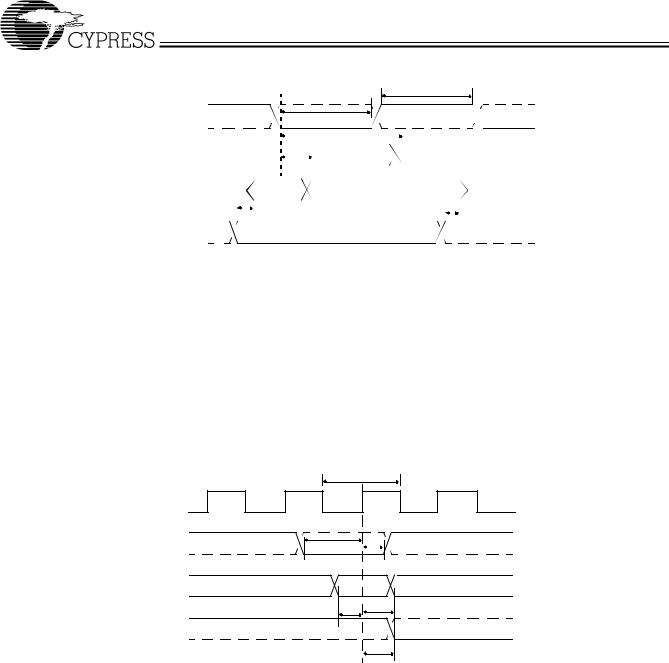
9.7Slave FIFO Asynchronous Read
tRDpwh
SLRD |
tRDpwl |
|
|
|
|
|
|
|
|
|
|
|
|
|
|
|
|
|
|
|
|
|
|
|
|
|
|
|
|
|
|
|
|
|
|
|
|
|
|
|
|
|
|
|
|
|
tXFLG |
||||||||||||||||||||||
|
|
|
|
|
|
|
|
|
|
|
|
|
|
|
|
|
|
|
|
|
|
|
|
|
|
|
|
|
|
|
|
|
|
|
|
|
|
|
|
|
|
|
|
|||||||||||||||||||||||
|
|
|
|
|
|
|
|
|
|
|
|
|
|
|
|
|
|
|
|
|
|
|
|
|
|
|
|
|
|
|
|
|
|
|
|
|
|
|
|
|
|
|
|
|
|
|
|
|
|
|
|
|
|
|
|
|
|
|
|
|
|
|
|
|
|
|
FLAGS |
|
|
|
|
|
|
|
|
|
|
|
|
|
|
|
|
|
|
|
|
|
|
|
|
tXFD |
|||||||||||||||||||||||||||||||||||||||||
|
|
|
|
|
|
|
|
|
|
|
|
|
|
|
|
|
|
|
|
|
|
|
||||||||||||||||||||||||||||||||||||||||||||
|
|
|
|
|
|
|
|
|
|
|
|
|
|
|
|
|
|
|
|
|
|
|
|
|
|
|
|
|
|
|
|
|
|
|
|
|
|
|
|
|
|
|
|
|
|
|
|
|
|
|
|
|
|
|
|
|
|
|
|
|
|
|
|
|
|
|
|
|
|
|
|
|
|
|
|
|
|
|
|
|
|
|
|
|
|
|
|
|
|
|
|
|
|
|
|
|
|
|
|
|
|
|
|
|
|
|
|
|
|
|
|
|
|
|
|
|
|
|
|
|
|
|
|
|
|
|
|
|
|
|
|
||
DATA |
|
|
|
|
|
|
|
|
|
|
|
|
|
N |
|
|
|
|
|
|
N+1 |
|
|
|
|
|
|
|
|
|||||||||||||||||||||||||||||||||||||
|
|
|
|
|
|
|
|
|
|
|
|
|
|
|
|
|||||||||||||||||||||||||||||||||||||||||||||||||||
|
|
|
|
|
|
|
|
|
|
|
|
|
|
|
|
|
|
|
|
|
|
|
|
|
|
|
|
|
|
|
|
|
|
|
|
|
|
|
|
|
|
|
|
|
|
|
|
|
|
|
|
|
|
|
|
|
|
|
|
|
|
|
|
|
|
|
|
|
|
|
|
|
|
|
|
|
|
|
|
|
|
|
|
|
|
|
|
|
|
|
|
|
|
|
|
|
|
|
|
|
|
|
|
|
|
|
|
|
|
|
|
|
|
|
|
|
|
|
|
|
|
|
|
|
|
|
|
|
|
|
|
||
SLOE |
|
|
|
|
|
|
|
|
|
|
|
tOEon |
|
|
|
|
|
|
|
|
|
|
|
|
|
|
|
|
|
|
|
|
|
|
tOEoff |
|
|
|
|
|
|
|
|
|
|
|
|
|
||||||||||||||||||
|
|
|
|
|
|
|
|
|
|
|
|
|
|
|
|
|
|
|
|
|
|
|
|
|
|
|
|
|
||||||||||||||||||||||||||||||||||||||
|
|
|
|
|
|
|
|
|
|
|
|
|
|
|
|
|
|
|
|
|
|
|
|
|
|
|
|
|
|
|
|
|
|
|
|
|
|
|
|
|
|
|
|
|
|
|
|
|
|
|
|
|
|
|
|
|
|
|
|
|
|
|
|
|
|
|
|
|
|
|
|
|
|
|
|
|
|
|
|
|
|
|
|
|
|
|
|
|
|
|
|
|
|
|
|
|
|
|
|
|
|
|
|
|
|
|
|
|
|
|
|
|
|
|
|
|
|
|
|
|
|
|
|
|
|
|
|
|
|
|
|
|
|
Figure 9-6. Slave FIFO Asynchronous Read Timing Diagram[13]
Table 9-7. Slave FIFO Asynchronous Read Parameters[16]
Parameter |
Description |
Min. |
Max. |
Unit |
|
|
|
|
|
tRDpwl |
SLRD Pulse Width LOW |
50 |
|
ns |
tRDpwh |
SLRD Pulse Width HIGH |
50 |
|
ns |
tXFLG |
SLRD to FLAGS Output Propagation Delay |
|
70 |
ns |
tXFD |
SLRD to FIFO Data Output Propagation Delay |
|
15 |
ns |
tOEon |
SLOE Turn-on to FIFO Data Valid |
|
10.5 |
ns |
tOEoff |
SLOE Turn-off to FIFO Data Hold |
|
10.5 |
ns |
9.8Slave FIFO Synchronous Write
|
tIFCLK |
|
|
IFCLK |
|
|
|
SLWR |
tSWR |
tWRH |
|
|
|
|
|
DATA |
Z |
N |
Z |
|
tSFD |
tFDH |
|
FLAGS |
|
|
|
tXFLG
Figure 9-7. Slave FIFO Synchronous Write Timing Diagram[13]
Table 9-8. Slave FIFO Synchronous Write Parameters with Internally Sourced IFCLK [15]
Parameter |
Description |
Min. |
Max. |
Unit |
|
|
|
|
|
tIFCLK |
IFCLK Period |
20.83 |
|
ns |
tSWR |
SLWR to Clock Set-up Time |
18.1 |
|
ns |
tWRH |
Clock to SLWR Hold Time |
0 |
|
ns |
tSFD |
FIFO Data to Clock Set-up Time |
9.2 |
|
ns |
tFDH |
Clock to FIFO Data Hold Time |
0 |
|
ns |
tXFLG |
Clock to FLAGS Output Propagation Time |
|
9.5 |
ns |
Note: |
|
|
|
|
16. Slave FIFO asynchronous parameter values use internal IFCLK setting at 48 MHz.
Document #: 38-08012 Rev. *F |
Page 35 of 48 |

|
|
|
|
|
|
CY7C68013 |
||
|
|
|
|
|
|
|
|
|
Table 9-9. Slave FIFO Synchronous Write Parameters with Externally Sourced IFCLK[15] |
|
|
|
|
||||
Parameter |
|
Description |
Min. |
|
Max. |
|
Unit |
|
|
|
|
|
|
|
|
||
tIFCLK |
IFCLK Period |
20.83 |
|
200 |
|
ns |
||
tSWR |
SLWR to Clock Set-up Time |
12.1 |
|
|
|
ns |
||
tWRH |
Clock to SLWR Hold Time |
3.6 |
|
|
|
ns |
||
tSFD |
FIFO Data to Clock Set-up Time |
3.2 |
|
|
|
ns |
||
tFDH |
Clock to FIFO Data Hold Time |
4.5 |
|
|
|
ns |
||
tXFLG |
Clock to FLAGS Output Propagation Time |
|
|
13.5 |
|
ns |
||
9.9Slave FIFO Asynchronous Write
tWRpwh
SLWR/SLCS# |
tWRpwl |
|
|
t |
tFDH |
|
SFD |
|
DATA |
|
|
|
|
|
|
|
|
|
|
|
|
|
|
|
|
|
|
|
|
|
|
|
|
|
|
|
|
|
|
|
|
|
|
|
|
|
|
|
|
|
|
|
|
|
|
|
|
FLAGS |
tXFD |
|
|
|
|
|
|
|
|
|
|
|
|
|
|
|
|
|
|
|
|
|
|
|
|||||||||||||||||||
|
|
|
|
|
|
|
|
|
|
|
|
|
|
|
|
|
|
|
|
|
|
|
|
|
|
|
|
|
|
|
|
|
|
|
|
|
|
|
|
|
||||
|
Figure 9-8. Slave FIFO Asynchronous Write Timing Diagram[13] |
|
|
|
|
|||||||||||||||||||||||||||||||||||||||
Table 9-10. Slave FIFO Asynchronous Write Parameters with Internally Sourced IFCLK [16] |
|
|
|
|
||||||||||||||||||||||||||||||||||||||||
Parameter |
|
|
|
Description |
|
|
|
|
|
|
|
|
|
|
|
|
|
|
|
|
|
|
Min. |
|
|
|
Max. |
Unit |
||||||||||||||||
|
|
|
|
|
|
|
|
|
|
|
|
|
|
|
|
|
|
|
|
|
|
|
|
|
|
|
|
|
|
|
|
|
|
|
|
|
|
|
|
|
|
|
|
|
tWRpwl |
SLWR Pulse LOW |
|
|
|
|
|
|
|
|
|
|
|
|
|
|
|
50 |
|
|
|
|
|
|
|
|
|
|
ns |
||||||||||||||||
tWRpwh |
SLWR Pulse HIGH |
|
|
|
|
|
|
|
|
|
|
|
|
|
|
|
70 |
|
|
|
|
|
|
|
|
|
|
ns |
||||||||||||||||
tSFD |
SLWR to FIFO DATA Set-up Time |
|
|
|
|
|
|
|
|
|
|
|
|
|
|
|
10 |
|
|
|
|
|
|
|
|
|
|
ns |
||||||||||||||||
tFDH |
FIFO DATA to SLWR Hold Time |
|
|
|
|
|
|
|
|
|
|
|
|
|
|
|
10 |
|
|
|
|
|
|
|
|
|
|
ns |
||||||||||||||||
tXFD |
SLWR to FLAGS Output Propagation Delay |
|
|
|
|
|
|
|
|
|
|
|
|
|
70 |
ns |
||||||||||||||||||||||||||||
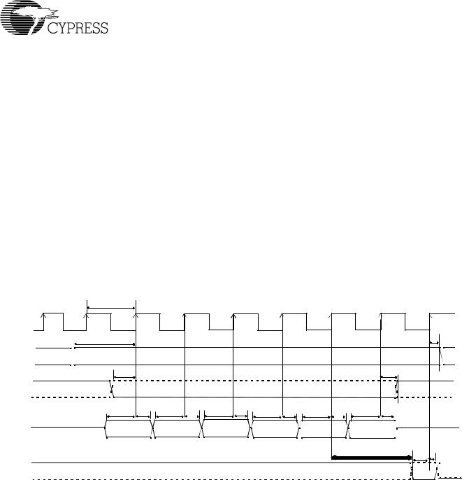
9.10Slave FIFO Synchronous Packet End Strobe
IFCLK
|
|
|
|
|
|
|
|
|
|
|
|
|
|
|
|
|
|
|
|
|
|
|
|
|
|
|
|
|
|
|
|
|
|
|
|
tPEH |
|
|
||
|
|
|
|
|
|
|
|
|
|
|
|
|
|
|
|
|
|
|
|
|
|
|
|
|
|
|
|
|
|
|
|
|
|
|
|
|
|
|
|
|
PKTEND |
|
|
|
|
|
|
|
|
|
|
|
|
|
|||||||||||||||||||||||||||
|
|
|
|
|
|
|
|
|
|
|
|
|
|
|
|
|
|
|
|
|
|
|
|
|
|
|
|
|
tSPE |
|
|
|
|
|
||||||
|
|
|
|
|
|
|
|
|
|
|
|
|
|
|
|
|
|
|
|
|
|
|
|
|
|
|
|
|
|
|
|
|
|
|
|
|
|
|
|
|
|
|
|
|
|
|
|
|
|
|
|
|
|
|
|
|
|
|
|
|
|
|
|
|
|
|
|
|
|
|
|
|
|
|
|
|
|
|
|
|
|
FLAGS |
|
|
|
|
|
|
|
|
|
|
|
|
|
|||||||||||||||||||||||||||
|
|
|
|
|
|
|
|
|
|
|
|
|
||||||||||||||||||||||||||||
|
|
|
|
|
|
|
|
|
|
|
|
|
|
|
|
|
|
|
|
|
|
|
|
|
|
|
|
|
|
|
|
|
|
|
|
|
|
|
|
|
|
|
|
|
|
|
|
|
|
|
|
|
|
|
|
|
|
|
|
|
|
|
|
|
|
|
|
|
|
|
|
|
|
|
|
|
|
|
|
|
|
tXFLG
Figure 9-9. Slave FIFO Synchronous Packet End Strobe Timing Diagram[13]
Table 9-11. Slave FIFO Synchronous Packet End Strobe Parameters with Internally Sourced IFCLK [15]
Parameter |
Description |
Min. |
Max. |
Unit |
|
|
|
|
|
tIFCLK |
IFCLK Period |
20.83 |
|
ns |
tSPE |
PKTEND to Clock Set-up Time |
14.6 |
|
ns |
tPEH |
Clock to PKTEND Hold Time |
0 |
|
ns |
tXFLG |
Clock to FLAGS Output Propagation Delay |
|
9.5 |
ns |
Document #: 38-08012 Rev. *F |
Page 36 of 48 |
|
|
|
|
CY7C68013 |
|||
|
|
|
|
|
|
|
|
Table 9-12. Slave FIFO Synchronous Packet End Strobe Parameters with Externally Sourced IFCLK [15] |
|
|
|||||
Parameter |
|
Description |
Min. |
Max. |
|
Unit |
|
|
|
|
|
|
|
||
tIFCLK |
IFCLK Period |
20.83 |
200 |
|
ns |
||
tSPE |
PKTEND to Clock Set-up Time |
8.6 |
|
|
ns |
||
tPEH |
Clock to PKTEND Hold Time |
2.5 |
|
|
ns |
||
tXFLG |
Clock to FLAGS Output Propagation Delay |
|
13.5 |
|
ns |
||
There is no specific timing requirement that needs to be met for asserting PKTEND pin with regards to asserting SLWR. PKTEND can be asserted with the last data value clocked into the FIFOs or thereafter. The only consideration is the set-up time tSPE and the hold time tPEH must be met.
Although there are no specific timing requirement for the PKTEND assertion, there is a specific corner case condition that needs attention while using the PKTEND to commit a one byte/word packet. There is an additional timing requirement that need to be met when the FIFO is configured to operate in auto mode and it is desired to send two packets back to back: a full packet (full defined as the number of bytes in the FIFO meeting the level set in AUTOINLEN register) committed automatically followed by a short one byte/word packet committed manually using the PKTEND pin. In this particular scenario, user must make sure to assert PKTEND at least one
clock cycle after the rising edge that caused the last byte/word to be clocked into the previous auto committed packet. Figure 9-10 below shows this scenario. X is the value the AUTOINLEN register is set to when the IN endpoint is configured to be in auto mode.
Figure 9-10 shows a scenario where two packets are being committed. The first packet gets committed automatically when the number of bytes in the FIFO reaches X (value set in AUTOINLEN register) and the second one byte/word short packet being committed manually using PKTEND. Note that there is at least one IFCLK cycle timing between the assertion of PKTEND and clocking of the last byte of the previous packet (causing the packet to be committed automatically). Failing to adhere to this timing, will result in the FX2 failing to send the one byte/word short packet.
|
tIFCLK |
|
|
|
|
|
|
|
|
|
|
|
|
|
IFCLK |
|
|
|
|
|
|
|
|
|
|
|
|
|
|
|
tSFA |
|
|
|
|
|
|
|
|
|
|
|
t |
|
|
|
|
|
|
|
|
|
|
|
|
|
|
FAH |
|
FIFOADR |
|
|
|
|
|
|
|
|
|
|
|
|
|
|
|
>= tSWR |
|
|
|
|
|
|
|
|
|
|
>= tWRH |
|
|
SLWR |
|
|
|
|
|
|
|
|
|
|
|
|
|
|
|
tSFD |
tFDH |
tSFD |
tFDH |
tSFD |
tFDH |
tSFD |
tFDH |
tSFD |
tFDH |
tSFD |
tFDH |
|
|
DATA |
X-4 |
|
X-3 |
|
X-2 |
|
X-1 |
|
X |
|
1 |
|
|
|
|
|
|
|
|
|
|
|
|
|
At least one IFCLK cycle |
tSPE |
tPEH |
||
|
|
|
|
|
|
|
|
|
|
|
|
|
||
|
|
|
|
|
|
|
|
|
|
|
|
|
|
|
PKTEND |
|
|
|
|
|
|
|
|
|
|
|
|
|
|
Figure 9-10. Slave FIFO Synchronous Write Sequence and Timing Diagram
Document #: 38-08012 Rev. *F |
Page 37 of 48 |