

Design of synchronous electromechanic converters
Unlike the direct current EMC an inductor of synchronous EMC is salient-pole and, as a rule, is located on rotor and similar to the poles of the direct current EMC.
Sometimes synchronous EMC are used, an inductor of which is a laminated cylinder with slots. In the slots of cylinder the exciting winding coils are placed, thus, the coils of every pole have different winding pitch, that assists to distributing of magnetic flux in air-gap by low, similar to sinusoidal. Such synchronous EMC are called nonsalient-pole generator. The exciting winding of synchronous EMC is fed from the direct current source. Happen also design of synchronous EMC, the inductor of which is located on stator. Such designs are called inverted.
Mainly synchronous EMC are used in the alternating current systems as three-phase generators (more frequent all), and sometimes as single-phase generators.
There are such excitation methods of magnetic field of synchronous EMC:
− the voltage from the outside direct current source is fed to the generator exciting winding through the contact rings and brushes (fig. 1.4)
− the exciting
winding of alternator current generator is connected to the armature
circuit of direct current generator (exciter) fastened on one shaft
with the rotor of synchronous EMC
(fig. 1.5)
the exciting
winding of alternator current generator is connected to the armature
circuit of direct current generator (exciter) fastened on one shaft
with the rotor of synchronous EMC
(fig. 1.5)
− contactless chart of exciting (fig. 1.6)
excitation by the permanent magnets.
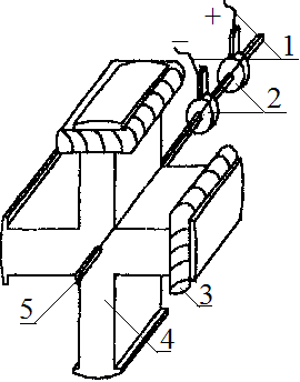
In the exciting circuit (fig. 1.4) the voltage from the strange direct current source is fed to exciting winding coils 3 through brushes 1 and contact rings 2, located on the laminated poles 4 of inductor. The package of inductor and contact rings are hardly fastened on a generator shaft 5. Fig. 1.4
T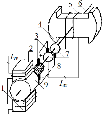 he
main lack of exciting circuit (fig. 1 4) consists in presence the
sliding contact, limitation of control range of excitation current
and dependence on the strange direct current source, therefore such
design is used for small power EMC.
he
main lack of exciting circuit (fig. 1 4) consists in presence the
sliding contact, limitation of control range of excitation current
and dependence on the strange direct current source, therefore such
design is used for small power EMC.
Powerful synchronous EMC are excited from the special exciter according to the chart shown on the fig. 1.5. In the excitation chart on fig. 1.5 the direct current Іvv flows through coils 1, located on poles 2 of exciter inductor. Fig. 1.5
Electromotive force of exciter armature 9 is taken from collector 8 by brushes 3 and is fed to the contact rings 7, connected with exciting winding 5 of synchronous EEC, the inductor of which is salient-poles.
Exciter armature 9, collector 8, contact rings 7 and poles 4 of synchronous EEC inductor are hardly fastened on the shaft 6. By the change of exciting current ІEE of the exciter it is possible to control an exciting current of synchronous EEC ІE.
By the lack of the exciting circuit, shown on fig. 1.5, there is a presence of unreliable sliding contacts. With development of power semiconductor technique the contactless synchronous EEC have got wide distribution.
The contactless synchronous generator, the electric circuit of which is shown on fig. 1.6, combines three synchronous machines: subexciter, an inductor of which is permanent magnet, inverted synchronous exciter and main synchronous generator.
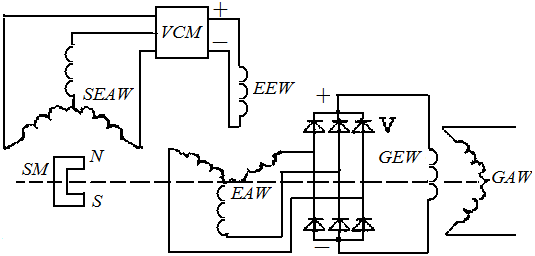
Fig. 1.6
Permanent magnet of subexciter SM, exciter armature winding EAW and exciting winding of the main generator GEW are fastened on one shaft.
At the rotor rotation of SM in the subexciter armature winding SEAW the three-phase EMF is created, which enters in a block of voltage control VCB, where it is rectifiered by diodes and farther as direct current voltage feeds an exciting winding of exciter EEW. Consequently EMF is created in subexciter armature winding, which is rectified by diodes V, which are revolved together with subexciter armature winding. Rectified by diodes V EMF feeds an armature winding of the main synchronous generator, in the three-phase winding of which EMF is induced also.
Advantages of contactless chart of excitation are independence on other direct current sources, absence of unreliable sliding contact, possibility of more wide range of excitation current control of main generator. The three-phase armature winding of synchronous EEC, as a rule, is located in the slots of laminated stator package.
In the inverted design of synchronous machines an armature winding is located on rotor and is connected with the external electric contour through rings and brushes. On such design the low-powered synchronous machines are built only.
On the aircraft of civil aviation the inverted synchronous generators are used, СГО-12, СГО-30, which have full power accordingly to 12 and 3О kVA. These generators are excited from the aircraft network of direct current.
Generators СГС-30 and ГО-16 of power 30 and 16 kVA are built by the classic chart and are excited also from the direct current aircraft network.
The СГС-60 and СГС-90 generators are excited according to the fig. 1.5.
On the modern aircraft they use the contactless synchronous generators ГТ-3O, ГТ-40, ГT-60, ГT-90 and ГT-120. Nominal phase voltage of generators − 120 V, frequency − 400 Hz.
The excitation of synchronous generators from the permanent magnets is used in some aviation converters of direct current into the three-phase alternating current by voltage 36 V, 400 Hz. This, for example, the ПT-125, ПT-200, ПT-600 and ПT-1000 converters. But the excitation of synchronous EEC from the permanent magnets thanks to the high reliability and diminished sizes is very perspective and already found the use on some aircraft for the basic generators.