

Features of asynchronous generators operation
Excitation of asynchronous generator is made by two modes − from a network and self-exciting with the help of capacitors. At first mode a rotor of asynchronous machine, powered on, is accelerated by primary engine up to oversynchronous frequency of rotation. A machine operates with the negative sliding, i.е. in the generator mode
s = (п1 — п2)/п1 < 0, (1)
where п1 − synchronous frequency of rotation; п2 − frequency of rotor rotation.
For
realization of this mode it is needed a consumption from the network
of magnetizing current about 25-30% of nominal, that
is the substantial lack of asynchronous generator at this method of
excitation. In addition, an asynchronous generator, consuming a
m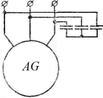 agnetizing
current, reduces the power factor of network.
agnetizing
current, reduces the power factor of network.
A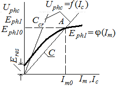 nother
way of asynchronous generator excitation consists in self-excitation
from the residual
magnetism of rotor which corresponds to
E.M.F. Eres.
In this case the battery of capacitors
(fig. 1, а)
is
Fig.
1, a
connected
to
terminals
of machine.
Increase of voltage
at self-excitating
goes
on up
to the
intersection of
magnetizing
curve Еph1
= φ(Im)
and CVC
of capacitor
Uphc = f(Ic)
(fig.1,
b),
where Iт
and Iс
− magnetizing
current and current through capacitor
respectively. At
constant
speed
of rotor the
o.c.
voltage
depends only on the value
of excitative
capacity. Generator is
excited, if
Fig.
1, b
capacity
more
than critical
one, i.e. С>Сcr.
nother
way of asynchronous generator excitation consists in self-excitation
from the residual
magnetism of rotor which corresponds to
E.M.F. Eres.
In this case the battery of capacitors
(fig. 1, а)
is
Fig.
1, a
connected
to
terminals
of machine.
Increase of voltage
at self-excitating
goes
on up
to the
intersection of
magnetizing
curve Еph1
= φ(Im)
and CVC
of capacitor
Uphc = f(Ic)
(fig.1,
b),
where Iт
and Iс
− magnetizing
current and current through capacitor
respectively. At
constant
speed
of rotor the
o.c.
voltage
depends only on the value
of excitative
capacity. Generator is
excited, if
Fig.
1, b
capacity
more
than critical
one, i.e. С>Сcr.
In the node of curves Еph1 = φ(Im) and Uphc = f(Ic) (point A on a fig. 1) an equilibrium occurs between voltages of generator and capacitors
Ic ω1L1 = Ic / ω1 C, (2)
where L1 = (Хs 1+ Хт)/ω1 − inductance of phase of generator stator winding; Хs1 − inductive resistance of dispersion of stator winding phase; Хm − inductive resistance of magnetizing contour; C − capacity, reduced to phase voltage.
From equality (2) it is possible to define dependence between inductance L1 and required excitative capacity C at given frequency f1 = ω1/2π:
L1 С = 1/ ω12 (3)
f1 = 1 / (2π√ L1 С) (4)
If to accept, that at idling the sliding s = 0, then f1 = f2, where f2 − electric frequency of rotor rotation. In this case
f2 ≈ 1/ (2π√ L1 С) (5)
So, at o.c.of asynchronous self-excited generator the parameters of oscillating loop are tuned automatically on frequency, equal to electric frequency of rotor rotation.
I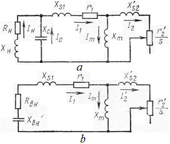 t
can consider the different operation
modes of generator
and calculate
by means of equivalent
circuit (fig. 2)
and vector
diagram of voltage
(fig. 3).
t
can consider the different operation
modes of generator
and calculate
by means of equivalent
circuit (fig. 2)
and vector
diagram of voltage
(fig. 3).
I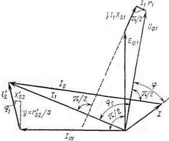 n
the equivalent
circuit at s < 0
the
resistance r2'/s
is a generating
element. If at loading generator, running
on a separate individual
network, a
frequency Fig.
2
of rotation п2
of primary engine is
supported
constant,
that frequency f1
and voltage
Uph
1
will some change at the change of load Zl
=
Rl
+jXl.
For
maintenance f1
= const
at loading it
is need to change
the speed
п2
of generator rotor rotation. Thus it
is settled a sliding
s,
corresponding to this load.
n
the equivalent
circuit at s < 0
the
resistance r2'/s
is a generating
element. If at loading generator, running
on a separate individual
network, a
frequency Fig.
2
of rotation п2
of primary engine is
supported
constant,
that frequency f1
and voltage
Uph
1
will some change at the change of load Zl
=
Rl
+jXl.
For
maintenance f1
= const
at loading it
is need to change
the speed
п2
of generator rotor rotation. Thus it
is settled a sliding
s,
corresponding to this load.
External characteristics of Fig. 3 asynchronous generators are strongly falling and depend on the value of excitant capacity (fig. 4, a, b). The strong voltage diminishing at the terminals of generator with the increase of load is explained by that the increase of internal voltage drop causes diminishing of magnetizing current and E.M.F., induced by the revolved magnetic field in the phase of stator (see a fig. 4.3). By other reason of diminishing . E.M.F. there is a demagnetizing action of secondary contour. External characteristics of asynchronous generators look like, characteristic for the generators of parallel excitation: after achievement by the load current of critical value Icr a turn-over of the external characteristic curve is observed. Thus currents of short circuit are small.