

Table of report contents
1. Rated data of motor.
2. Circuit of research of asynchronous motor.
3. Tables of measuring and calculations, used formulas.
4. Equivalent circuit of asynchronous motor with the parameters values indicated on it.
5. The graph of losses distribution.
6. Speed-torque characteristic of asynchronous motor and characteristic M = f(s).
7. Conclusions in relation to properties of asynchronous motor and explanation to the graphs.
Control questions
1. How the three-phase asynchronous motor with the squirrel-cage rotor is arranged?
2. What is a principle of asynchronous motor operation and why it is so called?
3. What sliding?
4. What terms of origin of the circular revolved magnetic field?
5. What rotation frequency of the magnetic field created by the stator winding does depend on?
6. What electromagnetic asynchronous motor power?
7. Why the nominal sliding of asynchronous motor must be minimum?
8. With what aim do carry out distribution of mechanical and magnetic losses of asynchronous motor?
9. How to change direction of motor rotation?
10. How to define a motor rated moment by its registration certificate data?
11. What advantages and lacks of asynchronous motor with the squirrel-cage rotor?
Calculation of electromagnets of direct-current а. Preliminary calculation of electromagnet. Calculation of key size of core
1.1. Electromagnets with external turning armature
During realization of preliminary calculation of electromagnets of the indicated type (fig. 1.1) next assumption is accepted:
1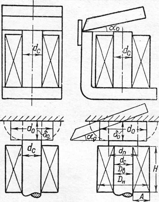 .
That part of critical force is taken into account only, which
created in a basic working gap.
This
force of F0
in future behaves to the axis of core.
.
That part of critical force is taken into account only, which
created in a basic working gap.
This
force of F0
in future behaves to the axis of core.
2. At the calculation of conductivity of this gap accept, that an armature is located in parallel to the butt end of core, on distance, equal to length of axis piece of core between the plane of its butt end and adjoining to its plane of armature (length of critical gap δ0, corresponds to the critical angle of armature turn α0)
3. Actual conductivity of this gap, determined by a Fig. 1.1 presence in it of the heterogeneous field, is replaced (in supposition of presences of the homogeneous field) by equivalent conductivity of cylinder with a height, to equal length of gap δ0 and diameter of d0 = ε∙dp, where a coefficient ε as though takes into account "goggling" of flux at the butt end of core. For simplicity of exposition the indicated equivalent conductivity and corresponding to it equivalent basic working gap is called a basic gap and basic conductivity, and an index "0" is appropriated characterizing them values, for example: diameter of d0, induction of B0 and so on.
For a preliminary calculation, as comparison showed results of analysis and experiment, done in пп. 1-3 assumptions itself are justified practically.
In future electromagnetic force in accordance with Makswell’s formula, shown in kilograms, ie determined so:
F0 = 5,1∙B02s0 / μ0, [kg], (1.1)
where B0 − induction in a basic gap, Wb/cm2; s0 − equivalent cross-section of basic gap, sm2; μ0 = 4π∙10-9 [Wb/A∙cm] ≈ 1,25∙10-8, Wb/A∙cm.
We will express a value В0 and s0 through the qualificatory size of electromagnet core − dс (diameter of core) and row of correction coefficients.
Because s0 = π∙d0/4, then, entering denotations of d0/dp = ε and dp/dc = τ we will define d0 = ε∙τ∙dc and, so, s0 = ε2∙τ2∙dc2, (1.2)
where dc − diameter of pole tip, cm; ε, τ − dimensionless coefficients of proportion, (in default of pole tip τ = 1); d0 and dc − accordingly equivalent diameter of basic gap and diameter of electromagnet core.
At position of armature, determined by a gap δ0, a basic part of complete MMF (wI)0, created at the set terms of coil operation, is spent on a basic working gap. We will designate a relation
(wI0 / wIf) = φ (1.2,a)
At this MMF (wI)0, spent on a basic gap, as is generally known, is determined at the homogeneous magnetic field by field strength Н0 and gap length δ0, i.е.(wI)0 = Н0∙ δ0, where (wI)0 is determined taking into account possible lowering of nominal MMF of coils (wI) in the process of service and gets out with some reserve, i.е.
(wI)f = χ∙(wI), (1.2,b)
where χ ≤ 1
Comparing (wI)0 and (wI)f, we will get: φ = Н0∙ δ0 / χ∙(wI)
or, because Н0 = B0/μ0, then φ = Н0∙δ0 / χ∙μ0∙(wI), from where
В0 = χ∙μ0∙φ∙(wI) / δ0 (1.3)
Substituted (1.2) and (1.3) in (1.1), we will get:
F0 = 4∙χ2∙τ2∙ε2∙μ0∙φ2∙dc2∙ (wI)2 / δ02 (1.4)
It is possible to reduce the expression of force to the similar formula, got of power balance of electromagnet :
F0 = 5,1∙(wI)02∙|dG0 / dδ0|
In this case follows in (1.4) to replace ε2 by the new coefficient εeq2 = δ02∙|d(ε2 / δ0) / dδ|, the value of which it easily to get from (1.4) and (1.2,а), substituded value of MMF from (1.2,а), (1.2,b) and derivative conductivity
dG0 / dδ = d(μ0∙ s0 / δ0) / dδ = 0,25∙π∙τ2∙dc2∙d(ε2 / δ0) / dδ
In these formulas φ, ε, εeq, τ, χ − dimensionless factors; wI − coil MMF, the value of which also can be expressed through the qualificatory size of electromagnet and row of dimensionless coefficients depending on the electromagnet operation mode and possible exceeding of temperature of heating of its coil Θper.
Here and in future they understand under Θper an average value along coil windows cross section a permissible exceeding of temperature, related to the environment temperature ϑenv = 350С, and chosen with some reserve, i.е. on 10 ÷15°C less than a maximum permissible value, indicated in ГОСТ for this class of isolation, compose the coil construction (table. 1).
In general cases, based on production experience, for the coils of electromagnets it is possible to recommend the following types of winding wire :
ПЭЛ and ПЭВ − for the devices of direct-current at the diameter of wire by a metal no more than 1,56 mm; for devices of alternating current at the diameter of wire no more than 0,55 mm.
ПЭЛШО − for the devices of alternating current at the diameter of wire from 0,55 to 0,7.
ПЭЛБО − in the devices of alternating current at a diameter from 0,56 to 1,00 mm and devices of direct-current with the diameter of wire higher 1,56 mm.
ПБД − in the coils of alternating current at the diameter of wire higher a 1,0 mm and direct − at the diameter more 1,56 mm.
ПСД − in the coils of especially responsible devices at the diameter of wire 0,56 and higher, operating in conditions, where the large increases of surrounding temperature are possible.
ПШКД − in those cases, when it is required to provide independence of resistance of coils from a temperature or application of copper thin wires not technological.
Table. 1
#
|
Isolation of wire, fabrication and treatment of coil
|
Rated values (°С) |
Reserve on most heated point and production error, °C |
Rated excess over tempe rature Θper, °C
|
|
Tempe rature |
Excess over 350С |
||||
1 |
Wire with a cotton or silk isolation (class of − Y). Coil is not impregnated with |
90 |
55 |
5-10 |
45-50 |
2 |
Wire enamel-insulated, there are paper gaskets between layers. Coil is not impregnated with |
90 |
55 |
5-10 |
45-50 |
3 |
Wire with cotton, silk or enamel isolation with paper gaskets (class of А). A coil is impregnated with or dipped in oily or oilmodified varnish |
105 |
70 |
5-10 |
60-65 |
4 |
Wire enamel-insulated or of the isolation of class A. Coil, compounded or saturated with compositions, attributed to the higher classes of thermiance |
120 |
85 |
10-15 |
70-75 |
5 |
A wire with glass-fibre isolation, coil, saturated with compositions on the basis of shellac or synthetic resins (class of В) |
130 |
95 |
10-15 |
80-85 |
6 |
A wire with glass-fibre isolation. Coil, saturated with compositions of enhanceable thermiance (class of F) |
155 |
120 |
15-20 |
100-105 |
7 |
A wire with glass-fibre isolation. Coil, saturated with organic-silicon resins (class of − Н) |
180 |
145 |
15-25 |
120-135 |
8 |
Naked wire - limited only in case of necessity to prevent some damage of nearby details. |
||||
We will consider determination of nominal MMF for the most often occuring electromagnets operation modes:
а) Continuous running duty of electromagnet
In a preliminary calculation suppose usually, that the cooling surface of direct-current coil Scol are external Sex and internal Sin its surface and ignore cooling of butt ends. Equality (fig. 1.1) is thus just:
Sex = π∙Dex∙H = π∙m∙(1 + 2n)∙d2c, (1.5,a)
Sin = π∙Din∙H = π∙m∙d2c, (1.5,b)
where Dex = dс + 2А; Din ≈ dc, and accordingly height of Н and width A winding of coil is expressed through a qualificatory size dc and dimensionless coefficients of proportion of m and n, i.е.
Н = m∙dс, A = n∙dс. (1.6)
In accordance with equation of coil heating in the continuous running duty we have:
Θper = R∙I2 / [h∙(Sex + α∙Sin)], (1.7)
where h − coefficient of heat emission from the surface of coil, W/0∙cm2; its value can be chosen for the exceeding of temperature Θper under formula:
h = 9,3∙10-4(1 + 0,0059∙Θper
α − coefficient, taking into account influence of windung method of coil on its heat emission: self-supported, shrouded, winded on a pipe, winded on a core or wireframe coil (hin = α∙h − coefficient of heat emission from the internal surface of coil, α = 0,9 − for the self-supported shrouded coil; α = 1,7 − for a coil, winded on a pipe; α = 2,7 − for a spool, winded on a core; α = 0 − for coils, having isolating framework of material, badly conducting warm, and coils of alternating current).
I − current, flowing in a coil, a; R − resistance of coil, refered to ϑper = Θper + 350С.
As is generally known,
R = 10-4ρ∙w∙lav / Sm = 10-4ρ∙π∙Dav∙w / Sm = ρ∙π∙(1 + n)dc∙w / (104∙Sm) (1-8)
where ρ − specific resistance of wire metal of coil at ϑper, Ω∙mm2/m. Specific resistance ρ of wire material it is necessary to refer to the permissible temperature of coil : ϑper = Θper + ϑenv, here ρ = ρ0(1 + α0∙ϑper), where ρ0 is specific resistance at 00С; α0 is a temperature coefficient of wire metal. For a copper wire α0 = 0,00393 within the limits of heating of 10÷1000С, ρ0 = 0,0162. For a leader copper a value ρ for most often meeting working temperatures is driven to the table.2:
Table. 2
ϑper (0С) |
ρ (Ω mm2/m |
ϑper (0С) |
ρ (Ω mm2/m |
ϑper (0С) |
ρ (Ω mm2/m |
20 |
0,01754 |
80 |
0,02170 |
105 |
0,02339 |
35 |
0,01857 |
90 |
0,02236 |
110 |
0,02370 |
40 |
0,01991 |
100 |
0,02300 |
120 |
0,02443 |
lav, Dav − length and diameter of middle loop of coil, cm;
Sm – cross-section of wire metal of coil, см2;
w − number of coil loops.
On determination of aperture occupation ratio of winding we will get:
fap = Sm∙w / HA = Sm∙w / m∙n∙dc2, (1.9)
from where we find the cross-section of wire metal
Sm = fap∙m∙n∙dc2 / w (1.10)
Putting (1.10) in (1.8), and then (1.5) and (1.8) in (1.7), we will define:
Θper = ρ(1 + n)∙w2I2 / [104∙ fap∙m2∙n∙h∙(1 + 2n + α)∙dc3]
From here it is easily to define necessary coils MMF:
w∙I = √[104∙ fap∙m2∙n∙(1 + 2n + α)∙h∙ Θper∙ dc3] / ρ(1 + n) (1.11)
Putting a value w∙I from (1.11) in (1.4), we find a basic formula, defined force of electromagnet :
F0 =[ 4∙104∙μ0∙φ2∙ε2∙χ2∙ fap∙τ2∙m2∙n∙(1 + 2n + α)∙ h∙ Θper∙ dc5] / [ρ(1 + n) δ02] (1.12)
From the last formula we find the key size of electromagnet :
dc = 5√[2∙103∙ ρ(1 + n)∙ F0∙ δ02] / [φ2∙ε2∙χ2∙ fap∙τ2∙m2∙n∙(1 + 2n + α)∙ h∙ Θper] (1.13)
Entering denotation
C1 = [2∙103∙ρ(1+n)] / [φ2∙χ2∙fap∙τ2∙m2∙n∙(1+2n+α)∙h∙Θper], (1.14)
we will rewrite formulas (1.12) and (1.13) so:
F0 = ε2∙dc5 (1.15)
and dc = 5√ [C1∙F0∙ δ02 / ε2], (1.16)
where F0 − force, kg, and δ0 – air gap, cm − are set by the critical terms of design;
εeq, ε − are dimensionless coefficients, taking into account buckling of flux and define equivalent conductivity of basic gap or her derivative ε = ε (δ0, dc), εeq = ε∙δ0, dc;
С1 − constant, determined by factors, included in a formula (1.14), namely: ρ, fap − constants, determined by the type of the chosen wire and method of its winding;
Θper, h, α − constants, determined by the terms of the permissible heating;
m, n, τ, φ − constants, determined by the optimally chosen sizes of coil and magnetic core;
2 ∙103 − constant, determined by chosen system of units.
About the practically recommended values of indicated constants, determined the task solution, approaching optimal terms, it will be rendered below. Possibility of close estimation of buckling coefficient ε, which in case of basic gap, formed by a cylindrical core and flat armature, can be expressed by next dependence: ε2 = 1 + [2,08 / (τ∙dc / δ0)].
A value ε for most electromagnets of the examined form is within the limits of 1 ÷ 1,6, however depends considerably on sizes δ0 and dp = τ∙dc.
Thus, the coefficient ε or εeq included in a formula (1.16) is the function of gap δ0 and diameter dc, that complicates the determination of key size dc from this equality.
Therefore for the calculation of dc next methodology can be recommended:
W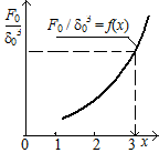 e
will transform a formula (1.16) so:
e
will transform a formula (1.16) so:
F0 / δ03 = (1/С1)(dc/ δ0)5∙ε2, или F0 / δ03 = χ5∙ε2 / С1, (1.17)
where χ = dc/ δ0 (1.18)
In the interval of the supposed change of δ0 / dс, or χ = dc/ δ0, for example 0,1 ≤ (δ0 / dс) < 1 or 1< χ ≤ 10, at constant value С1 and τ; set by Fig. 1.2 values χ = 1, 2, 3.., it is easily to define by a formula (1.17) a value F0 / δ03 and, thus, to build the curve of functional dependence of F0 / δ03 = f (fig. 1.2 and table. 3).
Then at the reverse raising of task, i. е. at a set value F0 and δ0, determine the size of F0 / δ03 and, using the got curve, find the relation χ = dc/δ0 and, so, for set value of δ0 the sought value dc.
At the change of values С1 and τ a family of analogical curves can be got.
By found value of key size dс it is easily to find the cross-section of wire metal Sm and number of coil loops w.
Really, because on (1.8)
R = 10-4∙ρ∙π∙(1 + n)∙dc∙w / Sm,, then w∙I = w∙U/R = 104∙U∙Sm / [π∙ρ∙(1 + n)∙dc], from where Sm = [ρ∙π∙(1 + n)∙dc∙w∙I] / 104∙U.
Table. 3
-
x
x2
x3
x5
ε2
εeq2
x5ε2
x5εeq2
F0 / δ03
1
2
3
On the other hand, MMF of coil by (1.11) with a glance (1.14) can be expressed so: w∙I = (4,5∙103 / φ∙χ∙τ)∙dc∙√(dc/C1)
So, the cross-section of wire is determined by formula
Sm = 1,41∙ρ∙(1 + n)∙dc2∙√(dc/C1 / (φ∙χ∙τ∙U), [сm2], (1.20)
and number of coil loops − by a formula:
w = fap∙HA / Sm = φ∙χ∙τ∙U∙fap∙m∙n∙√(C1/ dc) / [1,41∙ρ∙(1 + n)] or
w = C2∙U∙ √ (C1/ dc) (1.21)
where it is accepted: C2 = φ∙χ∙τ∙fap∙m∙n / [1,41∙ρ∙(1+n)] (1.22)
On occasion it is comfortably to use dependence:
w = U∙√{103∙ fap∙n / [ρ(1+n)( 1+2n+α)∙h∙Θper∙dc]}
The formulas got higher upon calculation of key size of electromagnet and winding data of coil are correct in the wide range of induction, however at its values, exceeded a limit, corresponding to steel saturation, the got dependences lost a fisical sense.
In accordance with it at the calculation of electromagnet core it is necessary to specify the value of induction, which a key size dс is got at.
A value of induction in steel, and so, its less value in a working air-gap, can be defined by the values of dс, ε and given initial terms of design (F0 and δ0), found in a preliminary calculation from a formula (1.1) :
B0 = 0,56∙10-4∙√ F0 / τ∙ε∙dc.
As specified, this value is specified in the subsequent project calculation of induction and under existent experience of design and production of electromagnets must not excel the values of order
(0,6÷0,8)∙10-4, Wb/cm2.
For the exception of the repeated calculations the value of induction in a basic working gap can be got approximately, before the calculation of key size of core, by formula:
B0 ≈ 4,8∙10-5∙[10√(F03 / δ04)] / τ∙(5√C1)
Nonconformance of the got value of induction with permissible indicates about unsuccessful choice of factors of preliminary calculation or accepted type of electromagnet for the set terms of its operation, required force and motion of armature.
Change of the got value of induction, as be obvious from the formula given above, at maintenance of the set terms of design (F0 and δ0) can be made due to clarification of coefficients of preliminary calculation in the real limits of their change.
So, for example, at the chosen value of п only due to the change of relation of coil height to the width of its window β = m / n
in limits from 1 to 10, it is possible to change induction В0 in 1÷2,5 time. A value of induction can be corrected due to clarification and other coefficients of preliminary calculation (τ, n, Θper and other).
In electromagnets with small critical air-gaps and insignificant leakage flux the induction in a gap can some exceed the legitimate values indicated higher.
In some designs of electromagnets, at which the initial terms of planning require creation of small critical forces and relatively large critical air-gaps, for maintenance real structural ratio and optimal terms on heating the induction in a air-gap it is needed to take considerably below than recommended.
In electromagnets with considerable critical forces and small air-gaps at maintenance of desirable design correlations and legitimate values of induction it is necessary agree to incomplete use of coil by heating.