

Invitation to a Contemporary Physics (2004)
.pdf5.5. The Genius of Carbon |
175 |
As with all other confined systems, the tube’s energy levels do not spread out into a wide continuous band, but instead group into subbands with band onsets at the discrete energies of the confined degrees of freedom. For single-wall nanotubes, these subbands are well spaced out, which suppresses thermal excitations even at room temperatures. In the metallic type, only two subbands cross the Fermi energy, so that a current through such a tube is carried by only these two subbands. Since each subband can support a quantum conductance of G0 = 2e2/h, we expect a perfect metallic nanotube to have a conductance of 2G0.
Experiments based on scanning-tunneling microscopic and spectroscopic studies have borne out all these predictions about the electronic structure and the strongly one-dimensional character of conduction of carbon nanotubes. These structures behave as true quantum wires. But, oddly enough, they also possess, at low temperatures (like 1 K), features that belong more naturally to quantum dots. This is so because, although nanotubes are much longer than they are wide (by a factor of 104), they still have a finite length, so that the boundary conditions at both ends impose a limit on the number of allowed wave vectors in the longitudinal direction — which means a completely quantized motion. So a nanotube is e ectively a zero-dimensional quantum system, with all the interesting consequences for electron transport and conduction — single-electron tunneling, resonant tunneling through molecular orbitals — that such a complete confinement implies.
This wealth of electronic properties is the source of a potential diversified technology. Because they are so thin yet so strong, carbon nanotubes, when stood on end and electrified, emit electrons from their tips at prodigious rates and at lower voltages than any other kind of known electrodes. They have all the desirable attributes of electron guns for electron microscopes, and field emitters for vacuumtube lamps or flat-panel display. Cees Dekker and others at Delft University of Technology in the Netherlands have further shown that they could build working electronic devices out of carbon nanotubes. For example, they have made a current flow through a semiconducting nanotube lying over two electrodes and switched it on and o by applying voltages to a nearby gate electrode, just as in a transistor. From the intrinsic properties of nanotubes, they expected this switching device to be more sensitive, run faster, and use much less power than a silicon-based transistor.
There is also the exciting possibility of engineering nanotube complexes by cutting, joining, and bending individual tubes. For instance, a junction of two tubes, one metallic and one semiconducting, should behave as a diode, permitting electricity to flow in only one direction, while other combinations of nanotubes with di erent band gaps could operate like light-emitting diodes and perhaps even nanolasers. And because carbon nanotubes conduct heat as well as diamond or sapphire, and have chemical bonds much stronger than those found in any metal, they can carry awesome amounts of electricity without overheating and vaporizing the wire. All these studies raise the hope that soon one could build tiny circuits entirely with these functionalized molecules.

176 |
Exploring Nanostructures |
Scientists have also made brave attempts to coax nanotubes into holding data. In one approach, they set up arrays of perpendicular tubes and inserted springlike molecules at the junctions where the wires crossed so as to create the onand o -states necessary for data storage. In another, they used an electric field to bend metallic tubes towards or away from a transverse semiconducting tube, thereby creating the onand o -states. In short, nanotubes are amazingly versatile molecules that can conduct, switch electric current and store information.
To build single-molecule devices that can perform functions identical or analogous to those of the conductors, transistors, diodes, memory devices and other key components of today’s microcircuits — that is the dream of the proponents of molecular electronics. But before that dream can turn into reality, either with nanotubes or some other more exotic molecules, we must gain a deeper understanding of their quantum behavior, an important aspect of which resides in that quintessential quantum property called spin.
5.5.3Summary
Carbon fullerenes and nanotubes are among the best-known naturally occurring nanostructures. They are appealing to theorists because of their high degree of symmetry, which allows detailed calculations. For the experimentalists, their distinctive hollow structure, unique electronic and mechanical properties o er a rich potential for studying quantum phenomena and developing applications in diverse areas.
5.6 Spintronics
The spin of the electron has its origins rooted deep in quantum mechanics and relativity. Yet, because it imparts an orientation to the charge carrier’s magnetic moment, it gives rise to a physically observable phenomenon, magnetism, which is apparent to every schoolchild and which is essential to the functioning of many common appliances. An electron does not spin like a top, but it can nevertheless be described by an intrinsic angular momentum (or spin), which is a permanent characteristic of the particle, as fundamental as charge. The quantization of angular momentum measured in a specified direction implies that the magnetic moment in that direction is also quantized. It confers on the electron two possible spin states, called spin-up and spin-down states. The movement of spin, like the electric current, can carry information among devices, but the existence of two controllable spin states suggests even more: a new kind of binary logic of ones and zeros. As spin — or its alter ego, the magnetic moment — can be readily manipulated by external magnetic fields, we may look forward to the development of a new generation of materials and structures based on the flow of spin in addition to the flow of charge

5.6. Spintronics |
177 |
that can perform much more than is possible with today’s electron-charge-based microelectronics devices. Some call this young field ‘magnetoelectronics,’ others ‘spintronics.’
5.6.1Spin Flow
As a general rule, the most energetically stable state in an atom is the one in which most or all of the electron spins cancel out in pairs, with the two spins in each pair pointing in opposite directions. The moments that have not got so canceled out could all line up and produce magnetism under the influence of some internal force. The most obvious candidate — the purely magnetic force between the unpaired electrons on neighboring atoms — turns out to be too weak to generate the kind of spin alignment observed in magnetic metals. Quantum theory predicts that there should be a much stronger interaction between neighboring atoms mediated by electrons. This ‘exchange’ interaction, strong but short-ranged, depends critically on the relative alignment of the two unpaired magnetic moments. For iron, cobalt, nickel, and the other materials that we qualify as ferromagnetic, parallel alignment of neighboring spins is favored, and the configuration of lowest energy in a ‘domain’ (small region) will be the one with all the spins pointing in the same direction. Other materials, known as antiferromagnets, see all neighboring spins in pairwise antiparallel alignment and, therefore, have no overall magnetic moment.
Let us note that magnetism is a cooperative behavior among atoms which derives from a purely quantum-mechanical process e ective only over distances of a few atomic spacings. That is why magnetic materials structures are much harder to design and control than semiconductors; they must be manipulated at the length scale of a nanometer or less to have any impact on their behavior, whereas semiconductors can exhibit novel properties already at carrier lengths of tens of nanometers.
Spin is more than magnetism: it can flow along with charge. What are the spin carriers? Where and how do they show up? How do they move about in materials?
The relevant electronic states in ferromagnets, just as in conductors or semiconductors, are those lying close to the Fermi energy, at the top of filled levels, and their densities of states explain to a large extent the transition to ferromagnetism. With spin present, each energy band splits in two, corresponding to the two possible spin orientations. In a nonmagnetic metal, such as copper, the spin bands remain lined up at the same energy level, and are equally occupied by the free electrons. So copper has no net magnetic moment, and the conduction electrons at the Fermi level are unpolarized, that is, equally distributed between the two spin orientations (Fig. 5.12). However, in a ferromagnetic metal, the spin-up and spin-down states are shifted in energy with respect to one another by the exchange interaction. This shift leads to an unequal filling of the spin bands, which is the source of the net magnetic moment for the metal, and also causes the spin-up and spin-down charge carriers to be unequal in number, character and mobility.
178 Exploring Nanostructures
|
|
E |
|
|
E |
|
|
|
|
|
|
|
|||
DOS |
EF |
DOS |
DOS |
EF |
DOS |
||
|
|
|
|
|
|
|
|
|
|
|
|
|
|
|
|
|
|
|
|
|
|
|
|
|
|
|
|
|
|
|
|
|
|
|
|
|
|
|
|
(a) |
(b) |
Figure 5.12: Density of states (DOS) that are available to electrons near the Fermi level (EF) in
(a) a normal metal and (b) a ferromagnetic metal whose spin-up states are completely filled.
Let us take cobalt as an example. In the atom, the d-level (so called because its orbital angular momentum equals 2 ) is incompletely filled, and the electrons that normally occupy it are weakly bound. In the metal, the tendency of the system to march towards the lowest-energy level demands that the spin-up (majority) states, shifted down by the exchange splitting, get all filled up first, so that the d-electron states at the Fermi level contain only spin-down (minority) electrons. There arises then an imbalance in spin populations at the Fermi level. The magnetic moment of cobalt is simply proportional to the di erence between the occupations of the two spin bands. At the same time, the highly polarized d-electrons, together with a few other electrons with di erent orbital angular momenta at the Fermi level, produce a partially spin-polarized flow of charge in which the majority of electrons are in a spin-aligned state.
Thus, a ferromagnetic metal may be used as a source of spin-polarized carriers injected into a normal metal, a semiconductor or a superconductor, or made to tunnel through a nonmagnetic insulating barrier. Although Fe, Co, Ni and their alloys are only partially polarized (with about 70% of the carriers in a spin state) and adequate for useful devices, there are continuing e orts to find 100% spinpolarized materials, which would strictly have only one occupied spin band at the Fermi level and, when used as filter, would permit true on–o operation, with an essentially infinite ratio of impedance between the two polarization states.
In the absence of any applied fields, magnetic materials have a complex largescale texture that results from several competing influences in submicron-sized elements. While the exchange interaction attempts to make the whole of an element magnetized in the same way, the magnetostatic force tries to split it into small domains of independent magnetizations, so as to form closed magnetic loops and keep stray fields to a minimum. However, the situation becomes simpler at the nanometric scale. For instance, in a small needle-shaped grain, the magnetization prefers to align along the long axis and occupy the whole element as a single
5.6. Spintronics |
179 |
domain; so it can remain highly stable against the influences of external fields. The existence of two stable magnetization states make such structures suitable for data storage applications. Thin films with a uniform composition and a proper thickness (like 1 or 2 nm) also have a simple field pattern, with magnetization lying in the plane of the layers rather than perpendicular to it. When made of soft magnetic materials, such as permalloy (Ni0.8Fe0.2) (whose magnetization is very sensitive to external fields, in contrast to the magnetically hard materials), those films have proved to be useful for a wide range of applications in sensors, memory elements and data storage. For this reason, thin film structures will play a central role in our discussion.
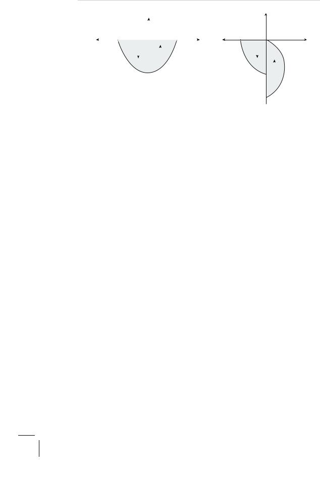
Now, let us see how a thin layer of magnetized ferromagnet a ects the flow of electrons (Fig. 5.13). The particles that can pass through the film are those having spins oriented in the same direction as the spins of the states available at the Fermi level; all others are reflected back at the surface. If the incident current is unpolarized, electrons passing through the magnetized material acquire this same spin bias, and the film acts like a spin polarizer. On the other hand, if the current is completely polarized, it will pass through if the spins of the carriers are aligned with those of the atoms in the layer; otherwise, its passage will be seriously hindered. The film operates then like a spin analyzer. So, for a 100%- polarized current, a magnetized ferromagnet can function either as a conductor
(a) High conductance |
(b) Low conductance |
|||||||||
|
|
|
|
|
|
|
|
|
|
|
|
|
|
|
|
|
|
|
|
|
|
|
|
|
|
|
|
|
|
|
|
|
|
|
|
|
|
|
|
|
|
|
|
|
|
|
|
|
|
|
|
|
|
|
|
|
|
|
|
|
|
|
|
|
|
|
|
|
|
|
|
|
|
|
|
|
|
|
|
|
|
|
|
|
|
|
|
|
|
|
|
|
|
|
|
|
|
|
|
|
|
|
|
|
|
|
|
|
|
|
|
|
|
E |
|
|
|
E |
||
|
|
|
|
|
|
|
||||
|
|
|
|
DOS |
|
DOS |
||||
DOS |
EF |
|
DOS |
|
||||||
|
|
|
|
|
|
|||||
|
|
|
|
|
||||||
|
|
|
|
|
|
|
|
|
|
|
|
|
|
|
|
|
|
|
|
|
|
|
|
|
|
|
|
|
|
|
|
|
|
|
|
|
|
|
|
|
|
|
|
|
|
|
|
|
|
|
|
|
|
|
|
|
|
|
|
|
|
|
|
|
|
|
|
|
|
|
|
|
|
|
|
|
Figure 5.13: Spin-polarized transport through a magnetized ferromagnetic layer. (a) When the current is 100% polarized and its polarization has the same orientation as the magnetization of the layer, the transmission is maximum. (b) When its polarization is opposite to the material magnetization, the conduction is severely reduced. Sketches of the densities of states at the Fermi level are also shown.

180 |
|
|
|
|
|
|
|
|
|
|
Exploring Nanostructures |
|
|
|
|
|
|
|
|
|
|
||||||
|
|
|
|
(a) High conductance |
(b) Low conductance |
||||||||||||||||||||||
|
|
|
|
|
|
|
|
|
|
|
|
|
|
|
|
|
|
|
|
|
|
|
|
|
|
|
|
|
|
|
|
|
|
|
|
|
|
|
|
|
|
|
|
|
|
|
|
|
|
|
|
|
|
|
|
|
|
|
|
|
|
|
|
|
|
|
|
|
|
|
|
|
|
|
|
|
|
|
|
|
|
|
|
|
|
|
|
|
|
|
|
|
|
|
|
|
|
|
|
|
|
|
|
|
|
|
|
|
|
|
|
|
|
|
|
|
|
|
|
|
|
|
|
|
|
|
|
|
|
|
|
|
|
|
|
|
|
|
|
|
|
|
|
|
|
|
|
|
|
|
|
|
|
|
|
|
|
|
|
|
|
|
|
|
|
|
|
|
|
|
|
|
|
|
|
|
|
|
|
|
|
|
|
|
|
|
|
|
|
|
|
|
|
|
|
|
|
|
|
|
|
|
|
|
|
|
|
|
|
|
|
|
|
|
|
|
|
|
|
|
|
|
|
|
|
|
|
|
|
|
|
|
|
|
|
|
|
|
|
|
|
|
|
|
|
|
|
|
|
|
|
|
|
|
|
|
|
|
|
|
|
|
|
|
|
|
|
|
|
|
|
|
|
|
|
|
|
|
|
(a) |
(b) |
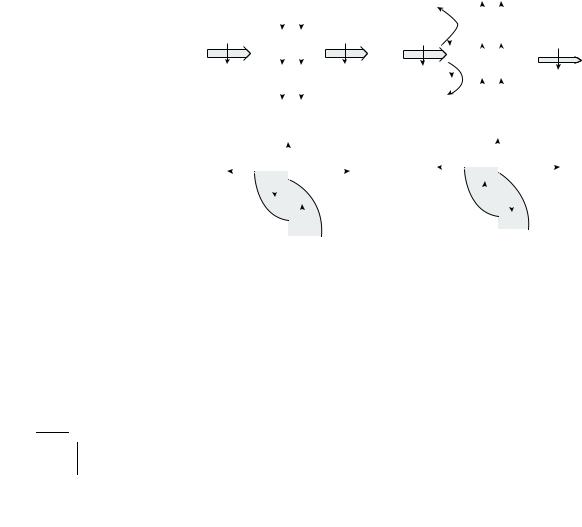
Figure 5.14: Spin-valve action. Spin-polarized transport through a sandwich consisting of layers of ferromagnetic metal, normal metal and ferromagnetic metal (a) when the magnetic moments in the ferromagnetic layers are aligned, and (b) when they are anti-aligned.
or an insulator, depending on whether its direction of magnetization is parallel or antiparallel to the spin polarization of the current.
5.6.2 Principles of Spintronic Devices
These basic principles of spin-dependent transport can be applied to a simple structure made of two ferromagnetic (e.g., permalloy or Co) thin films separated by a nonmagnetic metallic (e.g., Cu) spacer layer, whose role it is to stop any magnetic coupling between the layers but not to hinder the spin movement itself (Fig. 5.14). Electrons originating from one spin state at the Fermi level in the first film will be accepted by empty states of the same spin at the Fermi level in the second film. If the two magnetic films are magnetized parallel to each other, the minority (e.g., down-spin) electrons from the first film will go into minority unfilled states in the second, and the majority (up-spin) electrons from the first film will seek empty majority states in the second. But if the magnetization of the second film is now reversed so that the two films are magnetized in opposite directions, the identity of majority and minority will be reversed in the second film, and the minority (down-spin) electrons from the first film will look for empty majority (down-spin) states in the second, while the majority electrons will try to find empty minority states. Keeping in mind that the rate of any transition at some energy varies with the density of states at that energy, we can see from Fig. 5.14 that the conductance of the system increases (the resistance is reduced) when the magnetizations are in an aligned state, and decreases (the resistance is higher) in the anti-aligned state. We may aptly compare this e ect to that seen when light passes through an

5.6. Spintronics |
181 |
optical polarizer–analyzer. However, in the optical case, crossing the polarizer axes at 90◦ prevents light transmission, whereas here minimum conduction is obtained when the moments of the two ferromagnets are rotated 180◦ away from parallel. (The di erence in the rotation angles comes from the di erent spins of the electron and photon.)
We refer to the change in the electrical resistivity of a material due to the introduction of a magnetic field as magnetoresistance (MR), and measure it by the percentage change of the initial resistivity (when the field is absent). Most metals have very small MR. For instance, copper has MR 1% at a high magnetic field, H = 10 T (tesla), or 105 gauss (for comparison, the earth’s magnetic field is 0.7 gauss). But magnetic-layered structures, such as those described earlier, exhibit large MR 25% at H = 50 gauss and room temperatures, and even larger at higher fields. For this reason, we refer to the e ect observed here as giant magnetoresistance (GMR). As we have seen, it arises from a di erence in the carrier scattering rates when the magnetizations in the adjacent layers change their relative orientations.
The geometry we have considered, in which the current flows perpendicular to the plane of the layers, though conceptually simple, is much less practical (owing to the extremely low resistance across the nanolayers) than the more common arrangement in which the current flows in the layer plane. In this case, we still can observe the suppression of the spin-dependent scattering by the interfaces when the films go from an antialigned state to the aligned state, but the e ect is harder to visualize.
This simple metallic trilayer structure is called a spin valve. It is constructed so that the moment of a hard magnetic film is held fixed (pinned) by an antiferromagnetic (e.g., FeMn) overlay and serves as a reference, whereas the moment of the other layer can be easily flipped back and forth by an external magnetic field, and so will act as a control valve. We can design the system so that initially, when there is no field, the magnetization in the free layer lies antiparallel to the pinned layer, but when the field is applied, it turns to parallel orientation. This will lead to a decrease in resistance.
Magnetoresistance manifests itself also in another process characteristic of twodimensional magnetic nanostructures — spin-polarized tunneling. It occurs in trilayer systems, technically magnetic tunneling junctions (MTJs), that consist of two (one hard, one soft) ferromagnetic layers separated by an insulating (e.g., aluminum dioxide) film, typically 1 nm thick, which acts as a tunneling barrier. When a voltage is applied, electrons can quantum-mechanically tunnel through the spin-dependent energy barrier, with a probability proportional to the density of states available at the Fermi level in the acceptor layer, so that, when the moments of the two ferromagnetic layers are aligned parallel, there is a lower impedance than when they are antiparallel. The tunneling current, which flows through the junction perpendicular to the plane of the layers, is generally much lower than the current in the all-metal spin valve. However, the high resistance typical of tunneling devices

182 |
Exploring Nanostructures |
proved to be unattractive in terms of response time and noise, the more so because it increased as the junction dimensions decreased. For this reason, magnetoresistance in MTJs was a small e ect at room temperatures for a long time, until better growth techniques were developed for atomically sharp metal–insulator interfaces. Now the observed e ect comes close to the theoretical limit, and the resistance change can be as large as 47% in small fields. As they can operate at low current and exhibit high magnetoresitance in weak fields, MTJs would be unbeatable devices if they could be manufactured in large number at an a ordable cost.
5.6.3 Magnetic Recording
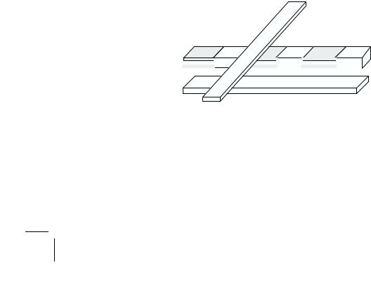
Both spin valves and magnetic tunnel junctions have been considered for applications, especially in the data storage industry where they are starting to play a meaningful role. The first application was for the read/write heads in magnetic recorders, which are components of every computer. At the heart of a state-of- the-art recording head is a magnetoresistive sensor element, which can pick up weak magnetic signals from magnetized domains (Fig. 5.15). To write information on the medium (a magnetically hard material coating on a tape or disk), a tiny electromagnet, also built into the recording device, magnetizes small segments of very narrow tracks on the medium, each magnetized segment containing a unit of data, or bit. Although there is no magnetic field emanating from the interior of a magnetic domain itself, flux lines may extend out of the medium at the ‘wall’ separating two adjacent domains. Whenever two adjacent domains are magnetized in opposite directions, there are ‘transitions’ at the wall, meaning that there are field lines extending out of or returning back into the medium, generated by uncompensated magnetic poles. When two bits are written successively in the same direction, there are no net transversal fields and hence no transitions at the domain wall. The presence of a transition indicates a binary 1, just as its absence, a binary 0.
in
 out
out
MR sensor
bit length
Figure 5.15: Magnetoresistive sensor element reading bits written on a track of a magnetized recording medium.

5.6. Spintronics |
183 |
The magnetoresistive sensor element is fabricated so that the moment in the soft magnetic layer lies parallel to the plane of a disk in the absence of any applied fields, but the moment in the fixed magnetic layer is always perpendicular to and directed towards the disk. When the head passes over the disk, reading the data as it goes, the moment at the transitions causes the moment in the soft layer to rotate towards a more anti-aligned or a more aligned direction with respect to the fixed magnetic moment, producing an increase or a decrease in resistance in the sensor element and signaling that a ‘1’ has been read.
Tens of millions of spin-valve read heads have already been made for the most advanced disk drives, and many more will soon come o the production line to replace the more traditional pick-up devices. Not far behind, MTJ read heads, which are capable of delivering greater signals at lower sensed fields, have been moving through the prototype state and will reach the manufacturing stage soon.
5.6.4 Data Storage and Processing by Spin
The second application that is expected to have a large economical impact is found in nonvolatile memory. (‘Nonvolatile’ means permanent, or retaining stored data even when power is switched o .) Magnetic disks provide the most widespread form of nonvolatile information-storage media, because of their low cost and long storage lifetime. The coating of a magnetic disk consists of grains of magnetic nanoparticles, which generally segregate randomly in size, coercitivity and shape. A recording density of 1 Gbit per square inch requires about a thousand grains per bit in today’s commercial disks, with typical grain sizes in the 10–20 nm range. There are continuing e orts to increase the storage density — by reducing the grain size and the number of grains per bit, and by engineering new materials — with the ultimate goal of quantized or single-particle-per-bit recording. We are still far from that goal, but tremendous advances have been made in recent years, which have allowed the density to double and the cost per bit to halve every three years (Problems 5.15 and 5.16).
Although the position of hard disks in data storage is not threatened by any means, their usefulness remains limited by the di culty in a fast retrieval of the stored information. We are rather more interested in examining possible improvements in another form of computer memory, an electronic storage known as dynamic random access memory (DRAM), which keeps temporarily most of the useful data, ready for instant access by the computer processing unit during a working session. Similar to a microprocessor, a memory chip is an integrated circuit made of millions of electronic components, organized in pairs. Each pair, consisting of a transistor and a capacitor, is a memory cell capable of containing a single bit of data. The capacitor holds the bit, a ‘1’ when the capacitor is more than half filled with electrons and a ‘0’ when it is not, whereas the transistor acts as a switch that lets the control circuitry on the memory chip interrogate the capacitor or change its state.
184 |
Exploring Nanostructures |
Useful as it is, DRAM has a serious drawback: charge leaks continually from the charged capacitors. It means that they have to be refilled before they discharge, an operation repeated thousands of times per second for every register, at a great cost in time and power, and generating a large amount of heat. It also means that every time you turn your computer on, its basic input/output system takes several seconds to perform a series of functions to check every memory address and transfer the basic operating codes from the hard disk to live memory.
Do you want to avoid that tedium of boot-up and ine ciency of refresh? Then MRAM (magnetic random access memory) is the answer to your wish because magnetism rather than electricity would be used to store data; and it would be more economical to operate because it requires just a small amount of electricity to switch the polarity of each memory cell. The idea of making a magnetic memory cell is rather simple: a layered structure, whether a spin valve or an MTJ, will be used to store the information, replacing the capacitor in current designs. In one scheme, the free layer is switched relative to the pinned layer to store a ‘0’ or a ‘1’, and measuring the resistance of the element indicates its magnetic state and hence the bit it holds. In another scheme, high-current pulses are used to write bits in the magnetically hard layer. To read the information, lower-current pulses are used to flip the magnetization in the soft layer, first one way and then the other. Comparing the change in measured resistance in each direction reveals the orientation of the magnetization in the hard layer and hence the stored data.
Each memory circuit consists of an array of multilayered elements fabricated with standard lithographic processes. In the chip based on spin valves, these elements are arranged in series and electrically connected by lithographic wires to form a ‘sense’ line, which stores the information. Additional current lines above and below the sense lines cross at right angles in an xy grid pattern, intersecting at each of the spin valves. These currents produce the magnetic fields needed to manipulate the magnetization of the data-storing elements (Fig. 5.16). A similar
Bit line
Sense line
Word line
Figure 5.16: Schematic representation of a data storage scheme, in which the memory cells are constructed of GMR elements connected in series along the sense line. The currents passing through the bit and word lines generate the magnetic fields that manipulate the GMR elements for writing and reading.