- •2 Methodical instructions to the task 1
- •Choice of the scheme of rectifier, type of filter and type of valve
- •The development of the scheme of transformer’s structure
- •Laminated tп; b) ribbon tл
- •The calculation of the electrical parameters of rectifier
- •The calculation of the smoothing filter
- •2.5 The rational design the throttle of smoothing filter
- •2.6 Definition of the initial data for calculation of transformer
- •3 Methodical instructions to the task 2
- •3.1 Choice of the dimension type of transformer’s magnetic conductor
- •3.2 Calculation of electrical parameters of transformer
- •3.3 The conclusions about design
- •3.4 The electrical scheme and the set of developed rectifying installation
- •3.5 Explanatory note
- •Lists of the literature Main
- •Additional
- •Reference
Methodical instruction contains two problems: task 1 contains the material on topic “Rectifying installations”, task 2 contains the material on topic “Transformers”. Each task has 100 variants. Number of problem’s variant corresponds to the two last digits of student card.
Task 1
To perform the calculation of the rectifying installation according to the average values of rectified voltage U0, load current I0 and permissible pulsation coefficient kпо in the load circuit L. The power network of alternating current is characterized by voltage Uс (effective value), frequency fс=50Hz and number the phases (single-phase or three-phase).
The performance of task provides for the performance of the following steps:
To choose the type of power network according to the number of the phases;
To choose the scheme of rectifier, type of filter and type of valve;
To create the scheme of transformer’s structure;
To calculate the electrical parameters of rectifier;
To calculate the smoothing filter;
To rational design the throttle of smoothing filter;
To define the initial data for calculation of transformer, to calculate its electrical parameters and to choose its magnetic conductor.
The initial data is given in the table 1.1, 1.2 and 1.3 with respect to the number of student card.
Table 1.1 – Initial data
Penultimate digit of student card |
0 |
1 |
2 |
3 |
4 |
5 |
6 |
7 |
8 |
9 |
U0, V |
-24 |
+24 |
-48 |
+60 |
-60 |
+120 |
-160 |
-220 |
+220 |
-240 |
kпо∙10-3 |
3 |
0,8 |
2 |
4,5 |
5 |
10 |
15 |
22 |
18 |
25 |
For students who have penultimate digit of student card 0, 1, 2, 3 and 4 the value of current in the load I0 is defined by the table 1.2 for other student it is defined by the table 1.3
Table 1.2 – Initial data
Last digit of student card |
0 |
1 |
2 |
3 |
4 |
5 |
6 |
7 |
8 |
9 |
I0, A |
28 |
26 |
24 |
23 |
21 |
19 |
17 |
14 |
12 |
11 |
Table 1.3 – Initial data
Last digit of student card |
0 |
1 |
2 |
3 |
4 |
5 |
6 |
7 |
8 |
9 |
I0, A |
4 |
5 |
6 |
7 |
8 |
9 |
10 |
2 |
3 |
1 |
Task 2
The main purpose of this task is to calculate the transformer. The initial data are voltage of supply network Uс with frequency fс=50Hz, voltage of phase’s emf U2x and current of secondary winding I2.
The performance of task provides for the performance of the following steps:
To choose the dimension type of transformer’s magnetic conductor;
To calculate the electrical parameters of transformer.
2 Methodical instructions to the task 1
Choice of the scheme of rectifier, type of filter and type of valve
As the rule the initial data contains the value of type of feeding network. But there are some cases when it is not known. Then it is necessary to define the number of phases (single-phase or three-phase).
The number of the phases is defined by the output power of rectifying installation. When the power is less that 1 kW it is used the single-phase network. When the power is higher than 1 kW, is used three-phase network.
A rectifier is an electrical device that converts alternating current (AC) to direct current (DC), a process known as rectification. Rectifiers have many uses including as components of power supplies and as detectors of radio signals. When only one diode is used to rectify AC (by blocking the negative or positive portion of the waveform), the difference between the term diode and the term rectifier is merely one of usage, i.e., the term rectifier describes a diode that is being used to convert AC to DC. Almost all rectifiers comprise a number of diodes in a specific arrangement for more efficiently converting AC to DC than is possible with only one diode. Before the development of silicon semiconductor rectifiers, vacuum tube diodes and copper oxide or selenium rectifier stacks were used.

Figure 1.1 – Structure scheme of rectifying installation
The elements of the scheme:
RI designates rectifying installation;
PPS designates primary source supply;
R designates rectifier;
Tr designates transformer;
F designates filter;
L designates load;
Un designates effective voltage;
U0 designates rectified voltage;
I0 designates load current;
kпо designates pulsation coefficient
The transformer Tr is used to transform the voltage’s value Uс of primary source into the value U2, that is intended by average rectified voltage U0 in the load circuit, transformation of phase’s number of primary voltage and providing of load galvanic isolation from primary source.
The scheme of rectifier R is used to transmit the type of current (from alternating current into direct pulsing one) and to transmit the number of rectifier’s phases.
The smoothing filter F is required to produce steady DC from a rectified AC supply. In its simplest form this can be just a reservoir capacitor or smoothing capacitor, placed at the DC output of the rectifier. There will still remain an amount of AC ripple voltage where the voltage is not completely smoothed. It is also used to decrease (smooth) the pulsing of rectified voltage of current up to the value, that is acceptable for the normal work of user.
To transform the alternating current/voltage into direct one, the rectifying installation uses vacuum tube. The valve is created by functional element that has the features of unidirectional conduction which is provided according to spasmodic changes value of flowing currents resistant, that depends on the applied voltage.
The modern rectifying installations have one of the most important functional elements it is semiconductor rectifier with unidirectional conduction of p-n junction. The calculation of transformer’s and smoothing filter’s parameters depends on choice of rectifier.
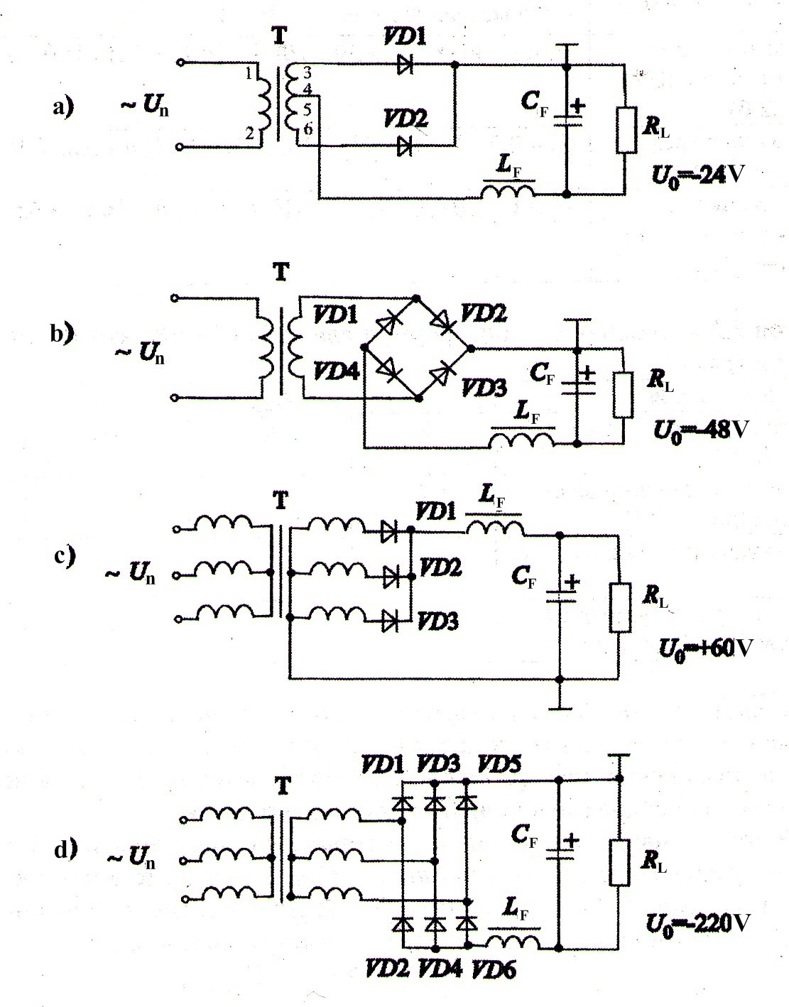
On the figure 2.2 it is shown the main schemes of rectifying installations. To choose the defined scheme of rectifying installation it is necessary to analyze the initial data Uс, U0, I0, kпо, the value of rectifier’s power load P0 = U0 ∙ I0 and the recommendations in the table 2.4 and [1.5].

Figure 2.2 – The main scheme of rectifying installations
The LC filter creates the rectangular form of current. It provides the maximum value of transformer’s activity factor and valve’s activity factor, that’s why the existence of such filter decreases the cost of rectifying installation when P0 is more than 100 W.
Table 2.1 – Technical characteristics of rectifying scheme with respect to current and voltage
Scheme of rectifying installation |
Range of usage |
Single-step double-phase (fig. 1.2, a) |
|
Double-step single-phase Gratz connection (fig. 1.2, b) |
|
Single-step three-phase (fig. 1.2, c) |
|
Double-step three-phase Larionov connection (fig. 1.2, d) |
|
For chosen scheme of rectifying installation it is possible to define the type of valve according to the table 2.2 (where m is number of phases).
Table 2.2 – Summary table for choosing type of valve (under the operation with LC-filter)
Scheme of rectifying installation |
m |
Iпр m |
Iпр ср |
Uобр |
Single-step double-phase (fig. 1.2, a) |
2 |
I0 |
I0/2 |
3,14U0 |
Double-step single-phase Gratz connection (fig. 1.2, b) |
2 |
I0 |
I0/2 |
1,57U0 |
Single-step three-phase (fig. 1.2, c) |
3 |
I0 |
I0/3 |
2,10U0 |
Double-step three-phase Larionov connection (fig. 1.2, d) |
6 |
I0 |
I0/3 |
1,05U0 |
The valve has to provide the defined the average value Iпр ср and amplitude value Iпр m of direct current.
The valve has to have the lowest reverse current, when the reverse voltage is active in the scheme.
The valve has to have the high electric strength (it is defined by the value of reverse allowed voltage Uобр доп).
It is necessary to use the valve that has the reverse voltage Uобр доп more (not lower than 20%) than the reverse voltage in the chosen scheme Uобр, and the carrying direct current Iпр доп is more (not lower than 20%) than maximum value of current Iмакс carrying through the valve, in other words Iпр доп ≥ 1,2Iмакс. It is also necessary that cutoff frequency will by fпред > 1 kHz when fc = 50 Hz.
Some times it is necessary to limit the number of part type of valves and increase their reliability. To provide the defined value of load current and increase electrical durability the valves can be connected sequentially or in parallel way with respect to each other.
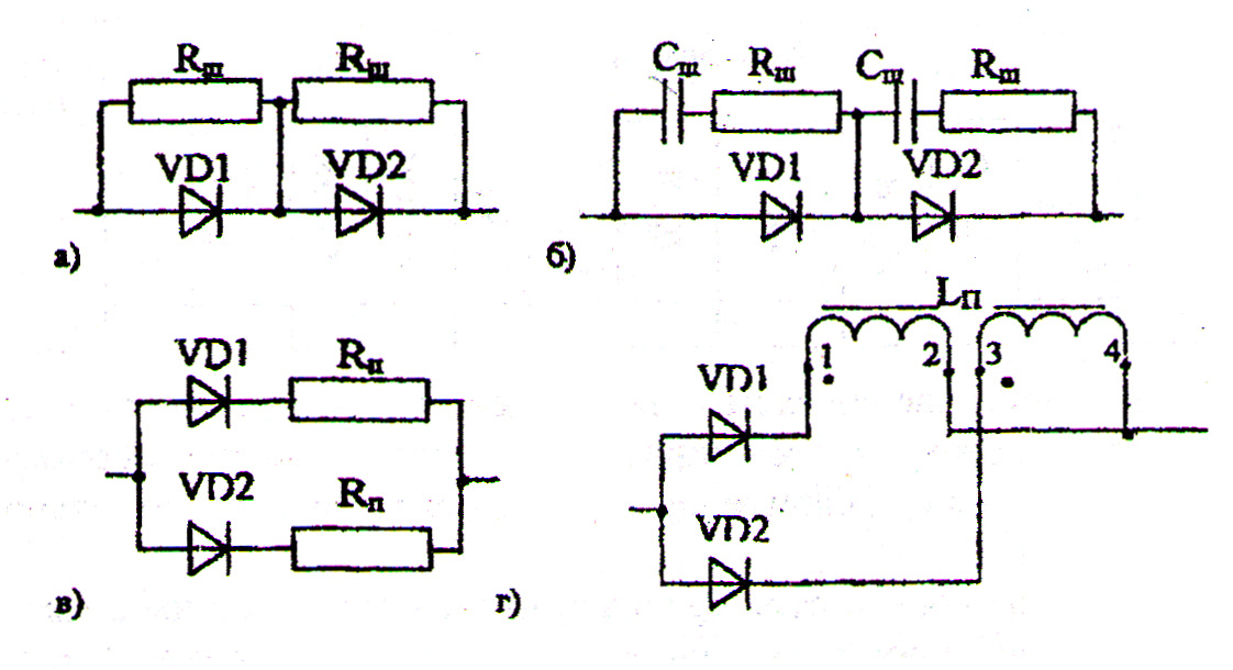
In that case when it is impossible to choose one diode according to the value of reverse voltage with Uобр доп > Uобр, then in each arm of scheme it is connected N sequential connected diodes. The number N of such diode in arm is defined by the formula
![]() .
(2.1)
.
(2.1)
For uniform distribution of reverse voltage on the diodes they have to be bridged by resistors RШ, as it is shown on the fig.1.3,a. The resistance of each such resistor is calculated by the formula:
![]() (2.2)
(2.2)
where IR = (3…5)Iобр.макс is current trough the resistor Rb,
Iобр.макс is maximum reverse current of diode.
In the rectifier of high power, when P0
> 1 kW, this way is not used because
of huge losses. That’s why for high power rectifying installations
it is used reactive potential divider (fig. 2.3, b), that has time
constant equals
![]() ,
in other words
,
in other words
![]() (2.3)
(2.3)
In the case when it is impossible to choose valve with respect to allowed value of direct current, then it is used the parallel connection of diodes as it is shown on the fig.2.3 c, d.


Figure 2.3 – Series (a, b) and parallel (c, d) connections of diodes into arms of rectifiers,
when it is absent the diode with necessary Uобр.доп and Iдоп
To provide the uniform distribution of rectified current Iвп.ср between parallel diodes switched into low power rectifying installations it is connected the resistors RП (fig.2.3, c), high power rectifiers P0 > 1kW it is connected current leveling reactor LП (fig.2.3, d). The values of each resistance of resistors RП is defined by the formula
![]() (2.4)
(2.4)
where UR ≥ (3…5)Uпр,Uпр is constant direct voltage drop of diode [12];
NП is the number parallel input diodes in each arm of rectifier defined by formula:
![]() ,
(2.5)
,
(2.5)
where Iпр.ср.макс is maximum allowed average rectified current of each diode of chosen type;
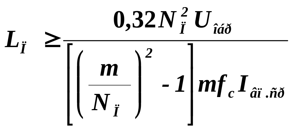
The value of inductance of current leveling electrical reactor LП placed on one diode magnetic core, is calculated by the formula
 ,
H
(2,6)
The obtained results are placed in the table 2.3.
Table 2.3 – Parameters of rectifier’s scheme
Scheme of rectifier |
Calculated parameters |
Type of valve |
Parameters of valve |
|||||||||||
m |
Iвп.ср, А |
Uобр. V |
Uпр. V |
IR, A |
UR, V |
N |
NП |
RШ, Ω |
СШ, μF |
LП, H |
|
Uобр.max, V |
I пр.ср, A |
|
|
|
|
|
|
|
|
|
|
|
|
|
|
|
|
The further calculations will be provided with respect to active resistance and reactance of transformer dispersion, because their values influence on the total internal resistance if we consider the separate phase of rectifier.
The coils resistance of transformer and leakage inductance of coils are defined according to the following formulas:
![]() (2.7)
(2.7)
![]() (2.8)
(2.8)
where kr and kt are the coefficients that depend on the scheme of rectifier, their values are shown in the table 2.8.
When the type of transformer core is chosen it is possible to define the values of the following parameters:
the maximum magnetic flux density
 (where BS
is the value of magnetic flux density of transformer magnetic
saturation);
(where BS
is the value of magnetic flux density of transformer magnetic
saturation);the number of winding bar S = 1, 2, 3;
the coefficient that defines the type of winding and placement of primary and secondary windings of transformer K0.
