


Special Operational Procedures and Hazards 10
•Dry snow: When the ambient temperature is below freezing.
•Wet snow: When the ambient temperature is near or above freezing.
De-icing is the process of removing ice from an airframe, whereas anti-icing is the process where the formation of ice on the airframe is prevented.
The effects of icing are wide-ranging, unpredictable and dependent on the individual aeroplane design. The magnitude of these effects is dependent upon many variables but the effects can be both significant and dangerous. Flight in known icing conditions is subject to the limitations laid down in OM Part B.
Basically the effects of icing are:
• |
Aerodynamic (ice alters the shape of the flying surface). Lift can be reduced by as much as |
|
|
|
30% and drag increased by up to 40%. This will significantly increase stall speed, reduce |
|
|
|
controllability and alter flight characteristics. |
|
|
|
10 |
||
|
|
||
• Weight (ice adds considerably to the mass of the aeroplane and affects the centre of gravity). |
|
||
Hazards |
|||
• |
Instruments: Ice forming on pitot tubes, static vents or angle of attack vanes can cause |
||
and |
|||
• |
errors in indications and give false attitude, airspeed, angle of attack and engine power |
||
Windscreen and canopies can become obscure, interference can be caused by ice on aerials, |
Procedures |
||
|
information for air data systems. |
|
|
|
under-carriage operation may be affected by ice in the wheel wells, and ice films can cause |
Operational |
|
|
skin friction. |
||
|
|
||
• |
Ice build-up on critical surfaces of the aeroplane may also break away during the take-off |
Special |
|
|
and be ingested into engines, possibly damaging fan and compressor blades. The formation |
||
|
|
||
of ice on an aeroplane on the ground may have a completely different effect on aircraft flight characteristics than ice formation in the air.
• Ice, frost and snow formed on the critical surfaces on the ground can have a totally different effect on aircraft flight characteristics than ice formed in flight.
Operators are to establish procedures to be followed when ground de-icing and anti-icing is required. Also, operators are not to allow aeroplanes to fly in conditions where icing is expected unless the aeroplane is certificated accordingly. Where an aeroplane is to be flown at night in icing conditions, a light is to be provided to illuminate the airframe to see if ice is accruing. The light is to be positioned and of such intensity so that it will not adversely affect the performance of any duty.
The Clean Aircraft Concept
During conditions conducive to aircraft icing take-off shall not be attempted when ice, snow, slush or frost is present, or adhering to the wings, propellers, control surfaces, engine inlets or other critical surfaces. This is known as the clean aircraft concept. Variables that can affect the formation of ice are;
•Ambient temperature.
•Aeroplane skin temperature.
•Precipitation rate and moisture content.
•De-icing/anti-icing fluid type, concentration and temperature.
147
10 Special Operational Procedures and Hazards
•Relative humidity.
•Wind.
Hazards and Procedures Operational Special 10
Where an aircraft is contaminated by ice on the ground the following methods are approved to be used for de-icing:
•The application of de-icing fluids (including ‘taxi through’ systems).
•Warming of the airframe by use of hot air blowers.
•Manually sweeping the surface where frost and light ice has accumulated.
De-icing and anti-icing on the ground can be either a one-step or a two-step procedure:
•In the case of a one-step procedure, de-icing and anti-icing are carried out at the same time using a combined de-icing and anti-icing fluid to both remove frozen deposits and to protect the de-iced surfaces for a limited period of time.
•The two-step procedure involves a process of ice removal followed by a process of anti-icing.
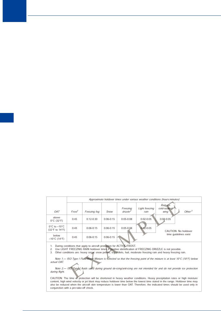
The fluids used in both processes have ‘holdover’ times quoted against the nature of the ice to be removed and/or protected against, and a range of ambient temperatures. The Holdover Time (HOT) is the estimated time during which the de-icing/anti-icing fluid will be effective. The aircraft must commence its take-off roll within the HOT, or the whole process, de-ice followed by anti-ice, must be repeated. The HOT is dependent on the OAT, temperature of the skin, type of precipitant, wind and type and concentration of fluid. An example of a HOT table is shown below, and pilots will be required to interpret the HOT. A similar table, or details of where to find a table, would be in Part A of the Ops Manual. Currently there are three types of fluid in general use for turbojet aircraft, type I, II or IV. (Type III can be diluted type II or IV cleared for use on turboprop aircraft). Aircraft must be treated symmetrically, and the pilot in command must ensure that the critical surfaces of the aeroplane are free of ice, snow, slush or frost just prior to take-off. This check shall be accomplished as close to the time of take-off as possible and is normally made from within the aeroplane by visually checking the wings.
EXAMPLE ONLY - NOT FOR OPERATIONAL USE
OAT Outside air temperature |
°C Degrees Celsius |
°F Degrees Fahrenheit |
Figure 10.1: Guideline for holdover times anticipated for ISO Type I fluid mixtures as a function of weather conditions and OAT
148

Special Operational Procedures and Hazards 10
Bird Strike Risk and Avoidance
The risk to aeroplanes from collisions with birds and the ingestion or birds or bird remains into engines will always be a hazard as long as aeroplanes share the sky with birds. Action and procedures can be put into effect to minimize the risk and the awareness of these procedures and compliance is the best means of reducing the hazard. ICAO operates IBIS, the ICAO Bird Strike Information System which is designed to collect and disseminate information on bird strikes to aircraft. Aeronautical charts are annotated with known areas where birds congregate and where wildlife sanctuaries have been established. Similarly, the well defined migratory routes of birds, together with the times of the year during which such migrations occur, are also published in AIP ENR 5.6. Providing information is supplied by pilots and ground observers concerning observed moment of concentrations of birds to air traffic units at aerodromes, i.e. position, height, quantity and direction of flight, such information can be relayed to aircraft in flight in the vicinity of aerodromes thus aiding awareness and prompting, if necessary, avoiding action. Pilots are required to report a potential bird hazard to the appropriate ground station.
Hazard to Aeroplanes
Apart from the obvious hazard of airframe damage, bird strikes can cause loss of power if air intakes to engines are clogged, cooling systems can fail if radiator cooling air intakes are clogged, hydraulic pipes exposed with lowered undercarriage can be fractured, and windows and clear vision panels can become obscured. The highest risk to aeroplanes is in close proximity to the ground where deviation from initial or final flight path is impractical, and when power settings are crucial. Aerodromes close to coastal areas and natural areas of habitat for birds are the most vulnerable. A knowledge of the heights at which birds fly, times of day when movement to and from roosting areas is likely and periods of mass migration will assist pilots, air traffic controllers and operators to minimize the risk to aeroplanes. Where birds are a continual risk to aeroplanes, airport authorities set up bird control units (BCUs) employing trained operatives and techniques to reduce the number of birds visiting an aerodrome.
Bird Strike Report
In the event of an aeroplane suffering a bird strike, the commander is to submit a written report of the incident after landing. ICAO Doc 9137 contains significant data regarding bird strikes, their effects and ways to minimize the likelihood.
Incompatible Land Use around Airports
Regulations should be placed on the use of land around airports to reduce the attractiveness to birds. Land uses which have caused specific problems at airports are:
•Fish processing.
•Agriculture.
•Cattle feed lots.
•Rubbish dumps and landfill sites.
•Factory roofs and carparks.
•Theatres and food outlets.
•Wildlife refuges.
•Lakes.
•Golf/polo courses.
•Animal farms.
•Slaughter houses.
Special Operational Procedures and Hazards 10
149

10 Special Operational Procedures and Hazards
Hazards and Procedures Operational Special 10
This does not mean that there will never be a carpark, or food outlet near an airport! But once an aerodrome is established the Authority will consider bird risk when assessing planning applications nearby.
Noise Abatement
EU-OPS requires noise abatement procedures to be established by operators for IFR operations in accordance with ICAO PANS OPS Doc 8168. Each state will detail noise abatement procedures for each aerodrome which can be found in the national Aeronautical Information Publication Section AD 2 and 3. The procedures have been designed for application to turbojet aeroplanes and comprise any one or more of the following:
•Use of noise preferential runways to direct the initial and final flight paths of aeroplanes away from noise sensitive areas.
•Use of noise preferential routes to assist aeroplanes in avoiding noise sensitive areas on departure and arrival, to direct aeroplanes away from noise sensitive areas located under or adjacent to the usual take-off and approach flight paths, and
•Use of noise abatement take-off or approach procedures, designed to minimize the overall exposure to noise on the ground and at the same time maintain the required level of flight safety.
An operator shall establish appropriate operating departure and arrival/approach procedures for each aircraft type in accordance with the following:
(a)The operator shall ensure that safety has priority over noise abatement, and
(b)These procedures shall be designed to be simple and safe to operate with no significant increase in crew workload during critical phases of flight, and
(c)For each aeroplane type two departure procedures shall be defined, in accordance with ICAO Doc. 8168 (Procedures for air navigation services, “PANS-OPS”), Volume I:
1.noise abatement departure procedure one (NADP 1), designed to meet the close-in noise abatement objective; and
2.noise abatement departure procedure two (NADP 2), designed to meet the distant noise abatement objective; and
3.in addition, each NADP climb profile can only have one sequence of actions.
Noise Preferential Runways
Preferred runway direction for take-off and landing, appropriate to the operation, are nominated for noise abatement to avoid noise-sensitive areas during the initial departure and the final approach phases of flight. Runways should not normally be selected for use for landing unless they are equipped with suitable glide path guidance, e.g. ILS or VASI (in VMC). A runway lead-in lighting system should be provided where it is desired to provide visual guidance along a specific approach path for purposes of noise abatement. Noise abatement should not be the determining factor in runway nomination under the following circumstances:
•If the runway surface conditions are adversely affected by water, snow, slush or ice etc.
•For landing in conditions when the ceiling is lower than 150 m (500 ft) above aerodrome
150

Special Operational Procedures and Hazards 10
elevation, or for take-off and landing when the horizontal visibility is less than 1.9 km (1900 m).
•When the crosswind component, including gusts, exceed 28 km/h (15 kt).
•When the tailwind component, including gusts, exceed 9 km/h (5 kt), and
•When windshear has been reported or forecast or when thunderstorms are expected to affect the approach or departure.
Noise Preferential Routes
Noise preferential routes are established to ensure that departing and arriving aeroplanes avoid over flying noise-sensitive areas in the vicinity of the aerodrome as far as practicable. In establishing noise preferential routes, turns during take-off and climb should not be required unless:
•The aeroplane has reached (and can maintain throughout the turn) a height of not less than 150 m (500 ft) above terrain and the highest obstacles under the flight path.
•The bank angle for turns after take-off is limited to 15° except where adequate provision is made for an acceleration phase permitting attainment of safe speeds for bank angles greater than 15°.
•No turns should be required coincident with a reduction of power associated with a noise abatement procedure, and
•Sufficient navigational guidance should be provided to permit aeroplanes to adhere to the designated route.
Note: PANS OPS Vol. 2 permits turns after take-off at 120 m (400 ft) and obstacle clearance of at least 90 m (300 ft) during the aeroplane turn. These are minimum requirements for noise abatement purposes.
In establishing noise preferential routes, the safety criteria of standard departure and standard arrival routes regarding obstacle clearance climb gradients and other factors should be taken into full consideration. An aeroplane shall not be diverted from its assigned route unless it has attained the altitude or height, which represents the upper limit for noise abatement, or it is necessary for the safety of the aeroplane.
Procedures
The state in which the aerodrome is located is responsible for ensuring that the aerodrome operators specify noise abatement objectives. The state of the operator is responsible for the approval of safe flight procedures developed by the aeroplane operator.
Limitations
Noise abatement procedures should not be selected if noise benefits cannot be expected. The pilot in command has the authority to decide not to execute a procedure if conditions preclude the safe execution of the procedure.
Take-off
Noise abatement procedures in the form of reduced power take-off should not be required in adverse operating conditions such as detailed in the previous paragraph under Noise Preferential Runways.
Special Operational Procedures and Hazards 10
151

10 Special Operational Procedures and Hazards
Hazards and Procedures Operational Special 10
Departure Climb
Aeroplane operating procedures for the departure climb are as follows:
•Procedures shall not be executed below a height of 240 m (800 ft) above aerodrome elevation.
•The procedure specified by an operator for any one aeroplane type should be the same for all aerodromes.
•There will be no more than two departure procedures to be used by one operator for an aeroplane type, one of which should be identified as the normal procedure and the other as the noise abatement procedure.
•Normal departure procedures typically include one of the two examples in the appendix to this chapter.
•All necessary obstacle data shall be made available to the operator and the procedure
gradient shall be observed.
•Power settings to be used after engine failure/shutdown or other reason for loss of performance during the procedure are at the discretion of the pilot, and noise abatement considerations no longer apply.
•The minimum level of thrust for the flap/slat configuration, after power reduction is the lesser of max climb power and that necessary to maintain the engine inoperative net climb gradient.
•The minimum thrust levels which vary as a function of flap setting, altitude and aeroplane mass are included in the OM. The settings are to take account of engine antiicing where applicable.
•Procedures are not to be used in conditions where windshear warning exists, or the presence of windshear or downburst activity is suspected.
•The maximum acceptable body angle specified for the aeroplane type shall not be exceeded.
Approach
In establishing noise abatement procedures the following shall be required:
•The aeroplane shall not be in any configuration other than the final landing configuration at any point after passing the outer marker or 5 NM from the threshold of the runway of intended landing (Stabilized Approach), whichever is earlier: and
•Excessive rates of descent shall not be required.
The following safety considerations should be taken into account. Glide path or approach angles should not require an approach to be made:
•Above the ILS glide path angle.
•Above the glide path of the VASI.
•Above the normal PAR final approach angle.
•Above an angle of 3° except when the ILS glide path requires higher.
The pilot should not be required to complete a turn on to final approach at distances less than will, in the case of visual operations, permit an adequate period of stabilized flight on final
152
Special Operational Procedures and Hazards 10
approach before crossing the threshold. In the case of instrument approaches, permit the aeroplane to be established on final approach prior to intercepting the glide path.
It has been found that reduced power/reduced drag approach techniques (or a combination of both) have proved to be both effective and operationally acceptable. The object of such techniques is to achieve uninterrupted descents at reduced power and drag by delaying the extension of flaps and landing gear until the final stages of the approach. These techniques result in higher than normal gear down and flap approach speeds.
Landing
Noise abatement procedures do not prevent the use of thrust reverse on landing. The use of a displaced landing runway threshold is only to be used for noise abatement if aeroplane noise is sufficiently reduced and the remaining runway distance is sufficient for all operational requirements.
Departure Climb Guidance
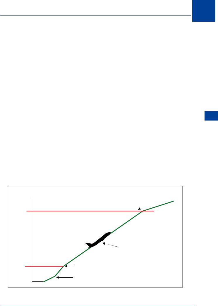
The following two examples of operating procedures for the climb have been developed as guidance and are considered safe in accordance with the conditions previously discussed under take-off. The first procedure (NADP 1) is intended to provide noise reduction in close proximity to the departure end of the runway. The second procedure (NADP 2) provides noise reduction to areas more distant from the runway end. The two procedures differ in that the acceleration segment for the flap/slat retraction is either initiated prior to reaching the maximum prescribed height or at the maximum prescribed height. To ensure optimum acceleration performance, thrust reduction may be initiated at an intermediate flap setting. The initial climbing speed to the noise abatement initiation point shall not be less than:
V2 + 20 km/h to 40 km/h (10 to 20 kt)
The noise abatement procedure is not to be initiated at less than 240 m (800 ft) above the aerodrome elevation.
Maintain positive rate of climb. Accelerate smoothly to en route climb speed. Retract flaps on schedule.
900 m
(3000 ft)
Climb at V2 + 10-20 kt. Maintain reduced power. Maintain flaps/slats in take-off position.
240 m |
Initiate power reduction at or above 240 m (800 ft) |
|
(800 ft) |
||
|
||
|
Take-off thrust V2 + 10-20 kt |
|
|
|
Figure 10.2: Noise abatement take-off climb. Example of a procedure alleviating noise close to the aerodrome (NADP 1)
Special Operational Procedures and Hazards 10
153
10 Special Operational Procedures and Hazards
Hazards and Procedures Operational Special 10
Transition smoothly to en route climb speed
900 m
(3000 ft)
|
Not before 240 m (800 ft) and whilst maintaining |
|
|
a positive rate of climb accelerate towards VZF |
|
|
and reduce power with the initiation of first |
|
|
flap/slat retraction. |
|
|
Or |
|
|
When flaps/slats are retracted and whilst |
|
240 m |
maintaining a positive rate of climb, reduce |
|
(800 ft) |
power and climb at VZF + 10-20 kt. |
|
|
|
|
|
Take-off thrust V2 + 10-20 kt |
|
|
|
|
Figure 10.3: Noise abatement take-off climb. Example of a procedure alleviating noise distant from the aerodrome (NADP 2).
Constant Descent Final Approach(CDFA) Profile
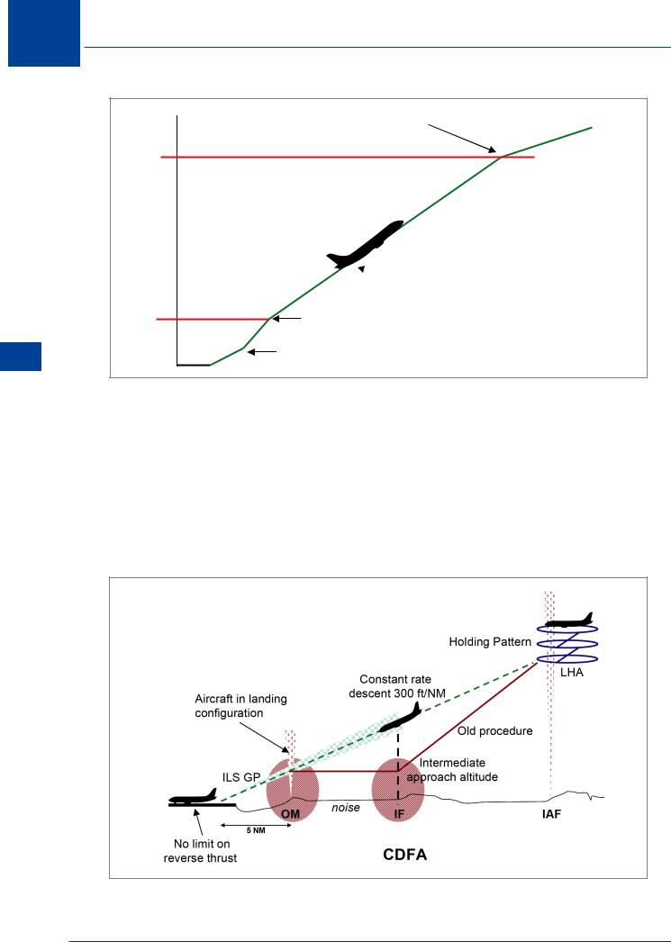
Non-precision approaches conducted by commercial air transport aeroplanes used by EU operators should be flown on CDFA profiles, to ensure that a Stabilized Approach can be conducted. In this case, the aeroplane descends from the lowest holding altitude (LHA) in the arrival stack and adopts a 300 ft/NM rate of descent that is maintained all the way to the runway threshold. This minimizes power adjustments and negates the need for the straight and level segment to intercept the glide path from below. It also reduces fuel burn and although this is not a major saving per flight, when multiplied by the annual total of approaches made in an operation, amounts to a significant economy.
Figure 10.4: CDFA
154