

326 |
Broadband Microstrip Antennas |
AR BW are slightly smaller than that of the corner-chopped cases because of its larger patch area.
8.4.4 Square MSA with a Diagonal Slot
A square MSA with a rectangular slot along its diagonal and the feed along its central axis is shown in Figure 8.17. The difference in the resonance frequencies of the orthogonal modes is caused by the rectangular slot, which makes the path lengths of the two diagonals unequal. In the ratio of length and width the slot governs the CP characteristics of the antenna for given patch and substrate specifications.
When a rectangular diagonal slot of length l = 0.75 cm and width w = 0.2 cm is cut at the center of the square MSA of L = 3 cm with a feed at y = 1.0 cm, RHCP is obtained. The AR and VSWR BWs are 23 MHz and 93 MHz, respectively, at f 0 = 2.963 GHz. These theoretical results follow the same trend as observed in the measured results [7].
In all the above cases, the ratio of the two orthogonal modes is very critical to yield CP with minimum AR at the resonance frequency. Due to the design limitations (e.g., software packages do have small error or sometimes approximations are made to reduce computation time) and fabrication error (tolerance in the patch dimensions and the substrate parameters), it is possible that the results may not be optimum and that fine-tuning of the dimensions is required. Whether to increase or decrease the dimensions can be determined by looking at the input impedance plot. If a loop is present in the plot, it implies that the separation between the two orthogonal modes is large, and hence it is to be reduced to obtain better AR. If there is only a slight bend in the impedance plot without any kink or loop, then the separation between the two modes is to be increased. In this regard, stub or notch configurations are more suitable as fine-tuning can be easily done to obtain lower AR with larger AR BW.
Figure 8.17 Square MSA with a diagonal slot.
Broadband Circularly Polarized MSAs |
327 |
8.4.5 Short or Chip Resistor-Loaded Square MSA
Instead of adding stubs or cutting slots or notches, in the square patch shorting posts or chip resistors could be used to obtain CP [15–17]. The resonance frequency of a square MSA changes when two shorting posts are placed symmetrically on either side of the center along the feed-axis as described in Section 7.2.3. When two shorting posts are placed closer to the center along the x -axis, the resonance frequency for the TM10 mode (oriented along the x -axis) changes slightly but it remains unaffected for the TM01 mode. When this configuration is fed diagonally as shown in Figure 8.18(a), it yields RHCP. When the feed is along the opposite diagonal, LHCP is obtained.
The measured resonance frequency of a square MSA of length L = 3 cm with er = 4.4 and h = 0.16 cm is 2.355 GHz. Two shorts are placed at a distance s = 0.48 cm and the patch is fed along the diagonal at (x , y ) = (−0.5, −0.5) cm to excite two orthogonal modes. The AR variation with frequency is shown in Figure 8.18(b). The BW for AR ≤ 3 dB is 22 MHz (0.9%) and the BW for VSWR ≤ 2 is 116 MHz (4.9%).
Both AR and VSWR BWs of the antenna increase when the shorting posts are replaced by chip resistors of value 4.7V, which is due to increase in the ohmic losses. The feed-point is shifted toward the corner to (−0.7, −0.7) cm and the separation between the resistors is increased to 0.78 cm. The BWs for AR ≤ 3 dB and VSWR ≤ 2 increase to 44 MHz and 164 MHz, respectively. However, the gain of the antenna decreases by 0.7 dB, when shorting posts are replaced by 4.7-V resistors. Therefore, the BW
Figure 8.18 (a) Square MSA with two shorts (or resistors) and (b) variation of AR with frequency: ( - - - ) shorts and ( —— ) resistors.
328 |
Broadband Microstrip Antennas |
increases at the expense of a decrease in the antenna gain. Comparison of shorts and resistors loaded square MSA is given in Table 8.1.
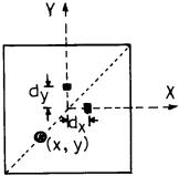
In the above chip resistor-loaded configuration, the loading affects only the mode along the x -axis. If the chip resistors are placed orthogonally, as shown in Figure 8.19, both the modes along the x - and y -axes are modified. By adjusting the spacing d x and d y of the resistors from the center, larger BW is obtained. When d x > d y , RHCP is obtained and when d x < d y , LHCP is obtained. For d x = 1.0 cm, d y = 0.5 cm and the feed at (x , y ) = (−0.65 cm, −0.65 cm), RHCP is obtained. The AR and VSWR BWs increase to 70 MHz and 237 MHz, respectively, and the center frequency also increases to 2.481 GHz. However, the gain of the antenna decreases from 4.35 dB to 2.45 dB as compared to the previous configuration.
8.4.6 Modified CMSAs and TMSAs
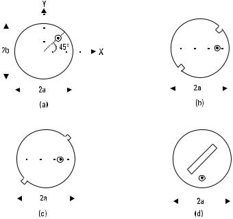
Similar to the modified square MSA, modified circular and triangular MSA configurations with a single feed also generate CP. Some of the modified circular patches are shown in Figure 8.20 [18–22]. A circular patch is modified to an elliptical patch as shown in Figure 8.20(a). CP is obtained
Table 8.1
Comparisons of Shorts or Resistors Loaded Square MSA
R |
s |
(x , y ) |
f 0 |
VSWR BW |
AR BW |
Gain |
||
(V) |
(cm) |
(cm) |
(GHz) |
(MHz) |
(%) |
(MHz) |
(%) |
(dB) |
|
|
|
|
|
|
|
|
|
0 |
0.48 |
−0.5, −0.5 |
2.375 |
116 |
4.9 |
22 |
0.9 |
5.05 |
4.7 |
0.78 |
−0.7, −0.7 |
2.404 |
164 |
6.8 |
44 |
1.8 |
4.35 |
|
|
|
|
|
|
|
|
|
Figure 8.19 Square MSA with two orthogonal chip resistors.
|
|
|
|
|
|
|
|
|
|
|
|
|
|
|
|
|
Broadband Circularly Polarized MSAs |
329 |
|||||||||||||||||||||||||||||||
|
|
|
|
|
|
|
|
|
|
|
|
|
|
|
|
|
|
|
|
|
|
|
|
|
|
|
|
|
|
|
|
|
|
|
|
|
|
|
|
|
|
|
|
|
|
|
|
|
|
|
|
|
|
|
|
|
|
|
|
|
|
|
|
|
|
|
|
|
|
|
|
|
|
|
|
|
|
|
|
|
|
|
|
|
|
|
|
|
|
|
|
|
|
|
|
|
|
|
|
|
|
|
|
|
|
|
|
|
|
|
|
|
|
|
|
|
|
|
|
|
|
|
|
|
|
|
|
|
|
|
|
|
|
|
|
|
|
|
|
|
|
|
|
|
|
|
|
|
|
|
|
|
|
|
|
|
|
|
|
|
|
|
|
|
|
|
|
|
|
|
|
|
|
|
|
|
|
|
|
|
|
|
|
|
|
|
|
|
|
|
|
|
|
|
|
|
|
|
|
|
|
|
|
|
|
|
|
|
|
|
|
|
|
|
|
|
|
|
|
|
|
|
|
|
|
|
|
|
|
|
|
|
|
|
|
|
|
|
|
|
|
|
|
|
|
|
|
|
|
|
|
|
|
|
|
|
|
|
|
|
|
|
|
|
|
|
|
|
|
|
|
|
|
|
|
|
|
|
|
|
|
|
|
|
|
|
|
|
|
|
|
|
|
|
|
|
|
|
|
|
|
|
|
|
|
|
|
|
|
|
|
|
|
|
|
|
|
|
|
|
|
|
|
|
|
|
|
|
|
|
|
|
|
|
|
|
|
|
|
|
|
|
|
|
|
|
|
|
|
|
|
|
|
|
|
|
|
|
|
|
|
|
|
|
|
|
|
|
|
|
|
|
|
|
|
|
|
|
|
|
|
|
|
|
|
|
|
|
|
|
|
|
|
|
|
|
|
|
|
|
|
|
|
|
|
|
|
|
|
|
|
|
|
|
|
|
|
|
|
|
|
|
|
|
|
|
|
|
|
|
|
|
|
|
|
|
|
|
|
|
|
|
|
|
|
|
|
|
|
|
|
|
|
|
|
|
|
|
|
|
|
|
|
|
|
|
|
|
|
|
|
|
|
|
|
|
|
|
|
|
|
|
|
|
|
|
|
|
|
|
|
|
|
|
|
|
|
|
|
|
|
|
|
|
|
|
|
|
|
|
|
|
|
|
|
|
|
|
|
|
|
|
|
|
|
|
|
|
|
|
|
|
|
|
|
|
|
|
|
|
|
|
|
|
|
|
|
|
|
|
|
|
|
|
|
|
|
|
|
|
|
|
|
|
|
|
|
|
|
|
|
|
|
|
|
|
|
|
|
|
|
|
|
|
|
|
|
|
|
|
|
|
|
|
|
|
|
|
|
|
|
|
|
|
|
|
|
|
|
|
|
|
|
|
|
|
|
|
|
|
|
|
|
|
|
|
|
|
|
|
|
|
|
|
|
|
|
|
|
|
|
|
|
|
|
|
|
|
|
|
|
|
|
|
|
|
|
|
|
|
|
|
|
|
|
|
|
|
|
|
|
|
|
|
|
|
|
|
|
|
|
|
|
|
|
|
|
|
|
|
|
|
|
|
|
|
|
|
|
|
|
|
|
|
|
|
|
|
|
|
|
|
|
|
|
|
|
|
|
|
|
|
|
|
|
|
|
|
|
|
|
|
|
|
|
|
|
|
|
|
|
|
|
|
|
|
|
|
|
|
|
|
|
|
|
|
|
|
|
|
|
|
|
|
|
|
|
|
|
|
|
|
|
|
|
|
|
|
|
|
|
|
|
|
|
|
|
|
|
|
|
|
|
|
|
|
|
|
|
|
|
|
|
|
|
|
|
|
|
|
|
|
|
|
|
|
|
|
|
|
|
|
|
|
|
|
|
|
|
|
|
|
|
|
|
|
|
|
|
|
|
|
|
|
|
|
|
|
|
|
|
|
|
|
|
|
|
|
|
|
|
|
|
|
|
|
|
|
|
|
|
|
|
|
|
|
|
|
|
|
|
|
|
|
|
|
|
|
|
|
|
|
|
|
|
|
|
|
|
Figure 8.20 Single-feed modified CMSA: (a) elliptical MSA and CMSA with (b) two notches,
(c) two stubs, and (d) a rectangular slot in the center.
when the ellipticity ratio (major axis to minor axis lengths) varies from 1.01 to 1.10 depending upon the substrate parameters. The feed is placed at an angle of 45° from the x -axis, which excites the two orthogonal modes with an equal amplitude and a 90° phase difference. In Figure 8.20(b), two notches are cut along the periphery of the circular patch at the diametrically opposite points. The feed is placed at an angle of 45° from the notch axis to excite the orthogonal modes in phase quadrature. Instead of cutting notches, two small stubs could be added as shown in Figure 8.20(c). Also, instead of cutting two notches or adding two stubs, only one notch or a stub could also be used. In Figure 8.20(d), a rectangular slot is cut at the center of the circular patch to yield CP. For all these antennas, the performance is similar to that of the modified square MSAs.
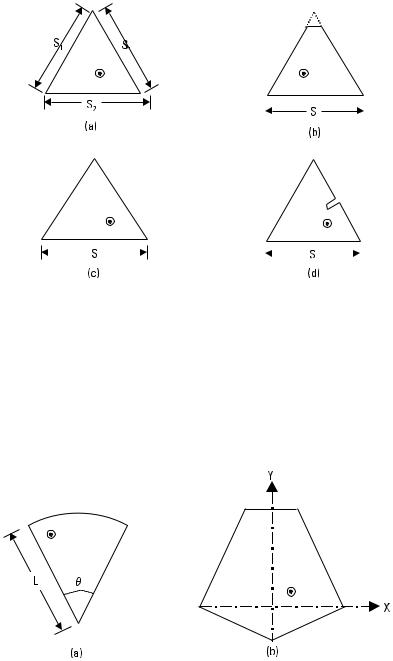
A modified ETMSA also generates CP [23–27]. Some of the modified ETMSA configurations are the nearly ETMSA (isosceles triangle with S1 /S2 = 1.01 to 1.10), tip-truncated ETMSA, ETMSA with a rectangular slot, and ETMSA with a notch (also called slit) along the periphery, as shown in Figure 8.21. Depending upon the feed-point location and dimensions, LHCP or RHCP is obtained.
330 |
|
|
|
|
|
|
|
|
|
Broadband Microstrip Antennas |
|||||||||||
|
|
|
|
|
|
|
|
|
|
|
|
|
|
|
|
|
|
|
|
|
|
|
|
|
|
|
|
|
|
|
|
|
|
|
|
|
|
|
|
|
|
|
|
|
|
|
|
|
|
|
|
|
|
|
|
|
|
|
|
|
|
|
|
|
|
|
|
|
|
|
|
|
|
|
|
|
|
|
|
|
|
|
|
|
|
|
|
|
|
|
|
|
|
|
|
|
|
|
|
|
|
|
|
|
|
|
|
|
|
|
|
|
|
|
|
|
|
|
|
|
|
|
|
|
|
|
|
|
|
|
|
|
|
|
|
|
|
|
|
|
|
|
|
|
|
|
|
|
|
|
|
|
|
|
|
|
|
|
|
|
|
|
|
|
|
|
|
|
|
|
|
|
|
|
|
|
|
|
|
|
|
|
|
|
|
|
|
|
|
|
|
|
|
|
|
|
|
|
|
|
|
|
|
|
|
|
|
|
|
|
|
|
|
|
|
|
|
|
|
|
|
|
|
|
|
|
|
|
|
|
|
|
|
|
|
|
|
|
|
|
|
|
|
|
|
|
|
|
|
|
|
|
|
|
|
|
|
|
|
|
|
|
|
|
|
|
|
|
|
|
|
|
|
|
|
|
|
|
|
|
|
|
|
|
|
|
|
|
|
|
|
|
|
|
|
|
|
|
|
|
|
|
|
|
|
|
|
|
|
|
|
|
|
|
|
|
|
|
|
|
|
|
|
|
|
|
|
|
|
Figure 8.21 Single-feed modified ETMSA: (a) nearly ETMSA, (b) tip-truncated ETMSA, (c) ETMSA with a rectangular slot, and (d) ETMSA with a notch.
8.4.7 Sectoraland Pentagon-Shaped MSAs
Sectoral MSA with a flare angle u = 65° or 70° and pentagon-shaped MSA as shown in Figure 8.22, also yield CP [1, 28]. In both cases, AR BW is on the order of 1%.
In the previous subsections, the single-feed modified MSA elements are analyzed for CP. These configurations can be designed to yield CP at
Figure 8.22 (a) Sectoraland (b) pentagon-shaped MSA.
Broadband Circularly Polarized MSAs |
331 |
other frequencies by using frequency-scaling techniques described in Section 2.2.7. Alternatively, a single-feed modified MSA can be designed using the following procedures.
8.4.8 Design Procedure for Single-Feed Circularly Polarized MSAs
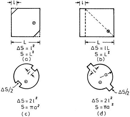
A square MSA with two corners chopped and a nearly square MSA are shown in Figure 8.23(a, b). To obtain CP with minimum AR, the dimensions of the perturbations are very critical as described earlier.
The approximate value of the total perturbation area Ds = l 2 for a two-corner-chopped square MSA can be obtained from the following relation [1, 29, 30]
Figure 8.23 (a) Square MSA with two corners chopped, (b) nearly square MSA, and CMSA with (c) notches and (d) stubs.
332 Broadband Microstrip Antennas
S S |
D |
|
2 |
|
|||
|
Ds |
|
Q 0 |
≈ |
1 |
|
(8.10) |
|
|
|
|
||||
where S = area of the square patch |
without perturbation |
= L 2, and |
|||||
Q 0 = unloaded quality factor of the patch.
For the nearly square MSA, the perturbation area Ds = l ? L is given
by
S S D |
|
|
|
Ds |
Q 0 |
≈ 1 |
(8.11) |
|
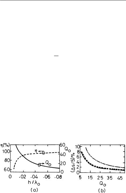
The value of Q 0 depends on the dimension of the patch and substrate parameters such as er , h, and tan d. The plot of Q 0 and efficiency h as a function of h /l0 for a square patch of L = 0.914 cm and er = 2.55 is given in Figure 8.24(a). The percentage variations of Ds /S versus Q 0 for both the configurations are shown in Figure 8.24(b). These curves are for only one value of er . For other values of er , Q 0 (er ) can be approximately calculated
as |
|
|
|
|
|
|
|
|
|
|
Q 0 |
√ |
|
|
|
|
|
Q 0 |
(er ) = |
er |
(8.12) |
|||||
|
|
|
|
|||||
|
|
|
|
|
|
|||
|
|
√2.55 |
||||||
For the given substrate parameters, the value of Q 0 is obtained first. The value of the corresponding efficiency should be higher than 90%. Next,
Figure 8.24 (a) Variation of Q 0 ( —— ) and h ( - - - ) with h /l 0 and (b) variation of Ds /S with Q 0 : ( —— ) corner-chopped square, ( - - - ) modified circular, and ( – ? – ) nearly square.
Broadband Circularly Polarized MSAs |
333 |
the percentage of perturbation Ds /S required for CP is calculated from (8.10) or (8.11), or read from the plots in Figure 8.24. Finally, the feed point is selected for the desired sense of CP polarization and input impedance matching.
Similarly, for the CMSA with two types of perturbation shown in Figure 8.23(c, d), the perturbation area Ds = 2l 2 can be obtained from [1, 29, 30]
Ds |
Q 0 |
≈ |
1 |
(8.13) |
||
|
|
|
|
|||
S S D |
|
|||||
|
|
K 11 |
||||
where K 11 = 1.84118 = first derivative of the Bessel function of order 1. The variation of Ds /S with Q 0 of CMSA is plotted in Figure 8.24. Once Ds /S is obtained, the procedure to design a single-feed CMSA for CP radiation is the same as that of the square MSA with perturbation. A similar concept can be extended to other shapes of the single-feed CP MSA.
8.5 Compact Circularly Polarized MSAs
The size of the above CP MSA configurations is large in the UHF frequency range. By combining the techniques to realize compact MSAs covered in Chapter 6 and CP MSAs discussed in previous sections, several compact CP MSA configurations are possible. Some of these are described in the following sections.
8.5.1 Modified Square Ring MSA
A nearly square ring MSA is shown in Figure 8.25(a). The outer dimensions of the ring correspond to that of a nearly square MSA, and a square slot is cut in the center of the patch, which increases the path length of the surface current thereby reducing the resonance frequency. The patch is fed along the diagonal, and the feed point is very close to the slot [29, 31]. The MNM method has been used to analyze the antenna. A nearly square MSA of lengths L 1 = 8.35 cm and L 2 = 8.2 cm, having a square slot of length l = 2.0 cm cut in the center with er = 2.5 and h = 0.159 cm, yields LHCP. The BW for AR ≤ 6 dB is 1.5% at f 0 = 1.043 GHz. The antenna can be made more compact by increasing the slot dimensions, but then impedance matching is not possible for a 50-V coaxial feed point at any location on
334 |
|
|
|
|
|
|
|
|
|
|
Broadband Microstrip Antennas |
||||||||||||||||||||||
|
|
|
|
|
|
|
|
|
|
|
|
|
|
|
|
|
|
|
|
|
|
|
|
|
|
|
|
|
|
|
|
|
|
|
|
|
|
|
|
|
|
|
|
|
|
|
|
|
|
|
|
|
|
|
|
|
|
|
|
|
|
|
|
|
|
|
|
|
|
|
|
|
|
|
|
|
|
|
|
|
|
|
|
|
|
|
|
|
|
|
|
|
|
|
|
|
|
|
|
|
|
|
|
|
|
|
|
|
|
|
|
|
|
|
|
|
|
|
|
|
|
|
|
|
|
|
|
|
|
|
|
|
|
|
|
|
|
|
|
|
|
|
|
|
|
|
|
|
|
|
|
|
|
|
|
|
|
|
|
|
|
|
|
|
|
|
|
|
|
|
|
|
|
|
|
|
|
|
|
|
|
|
|
|
|
|
|
|
|
|
|
|
|
|
|
|
|
|
|
|
|
|
|
|
|
|
|
|
|
|
|
|
|
|
|
|
|
|
|
|
|
|
|
|
|
|
|
|
|
|
|
|
|
|
|
|
|
|
|
|
|
|
|
|
|
|
|
|
|
|
|
|
|
|
|
|
|
|
|
|
|
|
|
|
|
|
|
|
|
|
|
|
|
|
|
|
|
|
|
|
|
|
|
|
|
|
|
|
|
|
|
|
|
|
|
|
|
|
|
|
|
|
|
|
|
|
|
|
|
|
|
|
|
|
|
|
|
|
|
|
|
|
|
|
|
|
|
|
|
|
|
|
|
|
|
|
|
|
|
|
|
|
|
|
|
|
|
|
|
|
|
|
|
|
|
|
|
|
|
|
|
|
|
|
|
|
|
|
|
|
|
|
|
|
|
|
|
|
|
|
|
|
|
|
|
|
|
|
|
|
|
|
|
|
|
|
|
|
|
|
|
|
|
|
|
|
|
|
|
|
|
|
|
|
|
|
|
|
|
|
|
|
|
|
|
|
|
|
|
|
|
|
|
|
|
|
|
|
|
|
|
|
|
|
|
|
|
|
|
|
|
|
|
|
|
|
|
|
|
|
|
|
|
|
|
|
|
|
|
|
|
|
|
|
|
|
|
|
|
|
|
|
|
|
|
|
|
|
|
|
|
|
|
|
|
|
|
|
|
|
|
|
|
|
|
|
|
|
|
|
|
|
|
|
|
|
|
|
|
|
|
|
|
|
|
|
|
|
|
|
|
|
|
|
|
|
|
|
|
|
|
|
|
Figure 8.25 Nearly square ring MSA with (a) coaxial feed and (b) quarter-wave transformer.
the ring. However, a quarter-wave transformer can be placed inside the ring to obtain impedance matching as shown in Figure 8.25(b).
Many variations of the nearly square ring MSA with square slot are possible yielding similar performance. Three variations are shown in Figure 8.26. These are a square ring with a nearly square slot, a corner-chopped square ring with a square slot, and a square ring with a corner-chopped square slot [31–33]. In these configurations, either the external or the internal dimensions generate orthogonal modes for CP.
Instead of a single-feed nearly square ring MSA and its variations, a square ring is fed at two orthogonal feed points with an offset polarizer inside the ring to realize compact configuration as shown in Figure 8.27. A square ring MSA of outer length L = 6 cm and inner slot length l = 4 cm
Figure 8.26 (a) Square ring MSA with a nearly square slot, (b) corner-chopped square ring MSA with a square slot, and (c) square ring MSA with a corner-chopped square slot.
|
|
Broadband Circularly Polarized MSAs |
335 |
|||||||||||||||||||
|
|
|
|
|
|
|
|
|
|
|
|
|
|
|
|
|
|
|
|
|
|
|
|
|
|
|
|
|
|
|
|
|
|
|
|
|
|
|
|
|
|
|
|
|
|
|
|
|
|
|
|
|
|
|
|
|
|
|
|
|
|
|
|
|
|
|
|
|
|
|
|
|
|
|
|
|
|
|
|
|
|
|
|
|
|
|
|
|
|
|
|
|
|
|
|
|
|
|
|
|
|
|
|
|
|
|
|
|
|
|
|
|
|
|
|
|
|
|
|
|
|
|
|
|
|
|
|
|
|
|
|
|
|
|
|
|
|
|
|
|
|
|
|
|
|
|
|
|
|
|
|
|
|
|
|
|
|
|
|
|
|
|
|
|
|
|
|
|
|
|
|
|
|
|
|
|
|
|
|
|
|
|
|
|
|
|
|
|
|
|
|
|
|
|
|
|
|
|
|
|
|
|
|
|
|
|
|
|
|
|
|
|
|
|
|
|
|
|
|
|
|
|
|
|
|
|
|
|
|
|
|
|
|
|
|
|
|
|
|
|
|
|
|
|
|
|
|
|
|
|
|
|
|
|
|
|
|
|
|
|
|
|
|
|
|
|
|
|
|
|
|
|
|
|
|
|
|
|
|
|
|
|
|
|
|
|
|
|
|
|
|
|
|
|
|
|
|
|
|
|
|
|
|
|
|
|
|
|
|
|
|
|
|
|
|
|
|
|
|
|
|
|
|
|
|
|
|
|
|
|
|
|
|
|
|
|
|
|
|
|
|
|
|
|
|
|
|
|
|
|
|
|
|
|
|
|
|
|
|
|
|
|
|
|
|
|
|
|
|
|
|
|
|
|
|
|
|
|
|
|
|
|
|
|
|
|
|
|
|
|
|
|
|
|
|
|
|
|
|
|
|
|
|
|
|
|
|
|
|
|
|
|
|
|
|
|
|
|
|
|
|
|
|
|
|
|
|
|
|
|
|
|
|
|
|
|
|
|
|
|
|
|
|
|
|
|
|
|
|
|
|
|
|
|
|
|
|
|
|
|
|
|
|
|
|
|
|
|
|
|
|
|
|
|
|
|
|
|
|
|
|
|
|
|
|
|
|
|
|
|
|
|
|
|
|
|
|
|
|
|
|
|
|
|
|
Figure 8.27 Square ring MSA with an inside offset polarizer.
is considered. The substrate parameters are er = 4.3, h = 0.16 cm, and tan d = 0.02. When a large slot is cut inside the square patch, the input impedance is large at the two orthogonal points inside the ring, so a quarter-wave transformer is used to transform this impedance to 100V. A 50-V coaxial feed point is located on the 100-V line, such that it provides equal amplitudes with a 90° phase difference to the two orthogonal points at the center of the two adjacent inner edges of the square ring patch. The measured and theoretical (obtained using IE3D) resonance frequencies are 830 MHz and 828 MHz, respectively. The BW for AR ≤ 3 dB is 8 MHz. This antenna has size reduction of 40% as compared to the square MSA for the same frequency of operation.
8.5.2 Modified Square MSA with Slits at the Edges
A compact CP MSA is also realized by cutting two pairs of slits of unequal lengths lx and ly of narrow width w (w << lx , ly ), at the four edges of the square patch as shown in Figure 8.28(a). For the feed-point location shown in Figure 8.28, RHCP is obtained when lx > ly , and LHCP is obtained when lx < ly . With an increase in lx and ly , the resonance frequency of the antenna decreases with a corresponding decrease in the BW. For L = 2.62 cm, lx = 0.97 cm, ly = 0.90 cm, w = 0.1 cm, er = 4.4 and h = 0.16 cm, RHCP is obtained at 2.272 GHz. The BW for AR ≤ 3 dB is 32 MHz (1.4%).
The gain of this compact CP MSA can be increased by placing a l/4 thick substrate of a high dielectric constant on top of the patch, which is