

276 |
Broadband Microstrip Antennas |
Figure 7.20 (a) Input impedance and (b) VSWR plots of double stub-loaded RMSA for dual-band operation.
A small loop may be noted at 2.813 GHz, but the radiation pattern at this frequency is conical. By using unequal stub lengths, the size of the smaller loop can be increased to yield triple-frequency response [29].
7.3.2.3 Single Stub-Loaded CMSA
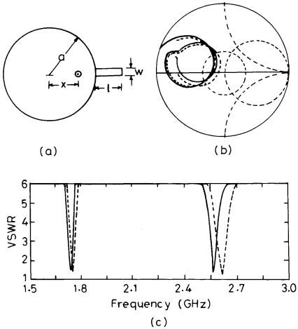
A CMSA with a single stub is shown in Figure 7.21(a). When the stub length is small, its resonance frequency is tunable as described in Section 7.2.1.4. However, when the stub length is comparable to l/4, dual-band operation is achieved [5]. For a = 3 cm, er = 2.33, h = 0.159 cm, and tan d = 0.001, the theoretical and the measured input impedance and VSWR plots for stub length l = 1.85 cm and width w = 0.4 cm are shown in Figure 7.21(b, c). The theoretical (obtained using the linear transmission line model) and the experimental dual-band resonance frequencies for different stub lengths are given in Table 7.8. The agreement between the theoretical and the experimental resonance frequencies are within 1% at the lower frequency f 1 and within 4% at the higher frequency f 2. The measured f 2 /f 1 ratio increases from 1.350 to 1.527 as l decreases from 3.40 cm to 1.60 cm.
The measured radiation pattern of the antenna in the E- and H-planes remains in the broadside direction at f 1. However, at f 2 for some cases, a dip in the broadside direction in the E-plane is noted as given in Table 7.8. It is observed that as f 2 /f 1 approaches near the ratio of 1.6588 (the ratio of the first two roots of the derivative of the Bessel function or 3.054/ 1.84118), the dip in the broadside in the E-plane becomes more pronounced.
Tunable and Dual-Band MSAs |
277 |
Figure 7.21 (a) Single stub-loaded CMSA and its (b) input impedance and (c) VSWR plots: ( - - - ) theoretical and ( —— ) measured.
This is due to the fact that higher resonance corresponds to the next higher order mode TM21, which has a conical pattern. As the frequency ratio deviates away from 1.6588, the dip reduces and finally disappears, yielding a broadside radiation pattern.
7.3.2.4 Double Stub-Loaded CMSA
A CMSA loaded by two stubs along the feed axis is shown in Figure 7.22(a). When either of the two stubs is comparable to l/4, dual-band operation is achieved. The two frequencies are varied by altering the individual stub

Table 7.8
Theoretical and Experimental Results of Single Stub-Loaded CMSA for Various Values of Stub Length l (a = 3 cm, x = 0.95 cm, er = 2.33, h = 0.159 cm, and tan d = 0.001)
Stub Length |
|
f 1 (GHz) |
|
f 2 (GHz) |
|
Measured Dip in |
l (cm) |
Theoretical |
Experimental |
Theoretical |
Experimental |
Measured f 2 /f 1 |
Broadside at f 2 (dB) |
3.40 |
1.515 |
1.507 |
2.105 |
2.034 |
1.350 |
0.0 |
2.75 |
1.595 |
1.593 |
2.190 |
2.162 |
1.357 |
1.5 |
2.50 |
1.640 |
1.635 |
2.275 |
2.242 |
1.371 |
2.0 |
2.30 |
1.680 |
1.679 |
2.385 |
2.330 |
1.388 |
2.5 |
2.20 |
1.700 |
1.695 |
2.450 |
2.385 |
1.407 |
3.1 |
2.00 |
1.732 |
1.720 |
2.600 |
2.503 |
1.455 |
4.4 |
1.85 |
1.750 |
1.744 |
2.635 |
2.565 |
1.471 |
5.6 |
1.60 |
1.777 |
1.769 |
2.765 |
2.701 |
1.527 |
9.1 |
|
|
|
|
|
|
|
278
Antennas Microstrip Broadband
Tunable and Dual-Band MSAs |
279 |
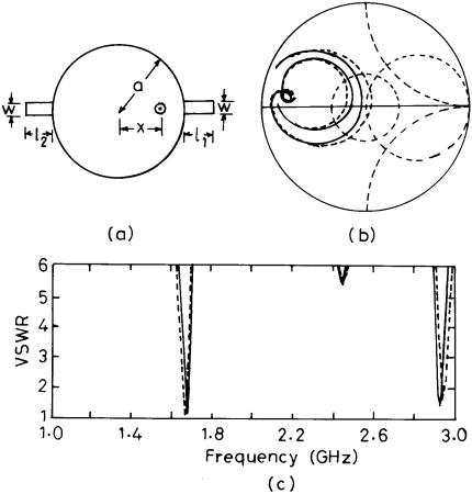
Figure 7.22 (a) Double stub–loaded CMSA and its (b) input impedance and (c) VSWR plots: ( - - - ) theoretical and ( —— ) experimental.
length. The theoretical and experimental input impedance and VSWR plots for stub lengths l1 = 1.75 cm and l2 = 2.0 cm are shown in Figure 7.22(b, c). The comparison between the theoretical and experimental dual-band resonance frequencies for various combinations of stub lengths l1 and l2 is given in Table 7.9. When the stub lengths are varied, the change in f 1 is less as compared to that in the f 2. As the stub length is increased, the BW at both the resonance frequencies decreases because of the decrease in the resonance frequency, which decreases h /l 0.
For a double stub-loaded CMSA, the radiation fields are in the broadside direction at f 1, whereas there is a dip in the broadside direction in the

Table 7.9
Theoretical and Experimental Results of Double Stub-Loaded CMSA for Various Stub Lengths (a = 3 cm, x = 0.95 cm, er = 2.33, h = 0.159 cm, and tan d = 0.001)
Stub Lengths (cm) |
|
f 1 (GHz) |
|
f 2 (GHz) |
|
Measured Dip in |
|
l1 |
l2 |
Theoretical |
Experimental |
Theoretical |
Experimental |
Measured f 2 /f 1 |
Broadside at f 2 (dB) |
2.55 |
1.50 |
1.590 |
1.582 |
2.190 |
2.142 |
1.354 |
0.0 |
2.55 |
1.20 |
1.600 |
1.590 |
2.210 |
2.168 |
1.363 |
0.0 |
2.25 |
1.00 |
1.660 |
1.647 |
2.385 |
2.294 |
1.393 |
1.8 |
2.00 |
1.00 |
1.695 |
1.685 |
2.465 |
2.431 |
1.443 |
6.0 |
2.00 |
0.50 |
1.715 |
1.705 |
2.565 |
2.468 |
1.448 |
7.0 |
2.25 |
2.25 |
1.585 |
1.598 |
2.591 |
2.583 |
1.616 |
13.5 |
1.75 |
2.00 |
1.660 |
1.679 |
2.950 |
2.935 |
1.748 |
11.0 |
1.65 |
1.75 |
1.678 |
1.685 |
2.982 |
2.973 |
1.764 |
5.0 |
|
|
|
|
|
|
|
|
280
Antennas Microstrip Broadband
Tunable and Dual-Band MSAs |
281 |
E-plane at f 2. The variation of dip in the broadside in the E-plane at f 2 is also given in Table 7.9. As the ratio f 2 /f 1 approaches 1.6588, the dip in the E-plane is more pronounced, indicating that higher resonance corresponds to the higher order TM21 mode of the CMSA. When the length of the two stubs are nearly equal, the ratio f 2 /f 1 is close to 1.6588, and hence there is a larger dip in the broadside at f 2. As f 2 /f 1 deviates from 1.6588, the amount of the dip reduces and finally disappears.
7.3.3 Notch-Loaded MSAs
Reactive loading to the patch could also be provided by cutting a notch or spur line in one of the edges of the MSA to obtain dual-band operation. It creates the same effect as the stub loading, with the advantage of reduced size [30–34].
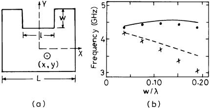
A square MSA with a rectangular notch of depth w along its nonradiating edge is shown in Figure 7.23(a). The antenna is similar to that of a C-shaped MSA, but it is fed along the diagonal, which excites orthogonal polarization at the first and second resonance frequencies. The antenna parameters are as follows: side length of the square patch L = 2.5 cm, notch length l = 1.0 cm, er = 1.79, h = 0.08 cm, and tan d = 3.2 × 10⁻⁴. The antenna is fed along the diagonal by a 50-V coaxial line at x = −y = 0.523 cm. For the square patch without the notch (w = 0), the resonance frequency is 4.3 GHz. The variation of the resonance frequencies f 1 and f 2 as a function
Figure 7.23 (a) Square MSA with a notch and (b) variation of resonance frequencies with w : ( —— ) f 2 theoretical and ( ? ? ? ) f 2 experimental, and ( - - - ) f 1 theoretical and ( x x x ) f 1 experimental.
282 |
Broadband Microstrip Antennas |
of the normalized notch width w /l is shown in Figure 7.23(b). With an increase in w, the variation of f 2 is small as compared to that of f 1, so the difference between the two resonance frequencies with orthogonal polarization increases.
7.3.4 MSAs Using Shorting Posts
In the previous two methods of reactively loaded MSAs, the frequency ratio f 2 /f 1 of dual-band operation is less than 2. For obtaining higher values of f 2 /f 1, various shorting configurations may be used. The shorting post is used in such a way that it selectively modifies the current distribution of one of the modes of the patch, thereby changing the resonance frequency of only that mode, whereas the other mode does not get perturbed significantly.
7.3.4.1 Dual-Band RMSA by Using Shorting Posts
An RMSA operating in the TM10 and TM30 modes has a broadside radiation pattern with the same polarization at the two frequencies. The ratio of their resonance frequencies is approximately three. A shorting post placed at the null position of the TM30 mode will not change its corresponding resonance frequency but will have a strong effect on the TM10 mode frequency [35].
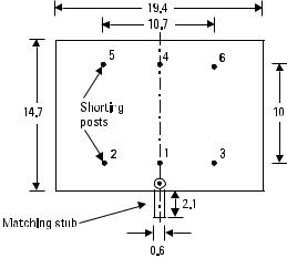
An RMSA with six shorting posts is shown in Figure 7.24. The patch is fabricated on a h = 0.3175 cm copper-cladded Rexolite 2200 substrate. The feed is chosen at the middle of the edge. A small open-circuited (capacitive) stub is attached at the feed point for neutralizing the reactance, especially
Figure 7.24 An RMSA with shorting posts for dual-band operation.
Tunable and Dual-Band MSAs |
283 |
at higher frequencies to improve the matching. The effects of successively adding more posts (each approximately 0.05 cm in diameter) at the positions indicated in Figure 7.24 are shown in Table 7.10. Since all these posts are located at the nulls of the TM30 mode, f 2 remains constant at around 1,865 MHz, while f 1 varies from 613 MHz to 891 MHz. The ratio f 2 /f 1 varies from 3.0 to 2.1, which could be lowered by using more shorting posts.
The radiation pattern remains in the broadside direction at both the frequencies with the same polarization. However, a sidelobe at f 2 appears in the E-plane pattern, which is due to the large spacing (normalized with respect to the free-space wavelength) between the two radiating edges of the patch. It can be easily reduced or even removed by using substrate with higher er .
7.3.4.2 Dual-Band RMSA Using a Single Short
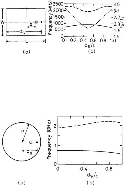
A compact dual-frequency RMSA using a single shorting post is shown in Figure 7.25(a). The patch dimensions are L = 3.73 cm and W = 2.487 cm, and the feed point is kept within a few millimeters from the shorting post. The substrate parameters are er = 4.4 and h = 0.0762 cm. The diameter of the shorting post is 0.064 cm, and the feed diameter is 0.126 cm. When the location d s of the shorting post is changed, the two resonance frequencies vary as shown in Figure 7.25(b). The lower resonance frequency f 1 varies in the range of 722–950 MHz and the higher resonance frequency f 2 varies in the range of 1,900–2,310 MHz. This yields a frequency-tuning range of 2.0–3.2. When the shorting post is near the edge of the patch, it gives a maximum separation of frequencies. The antenna has a broadside radiation pattern at both the frequencies [36, 37].
Table 7.10
Variation of Resonance Frequencies with a Number of Shorting Posts of Multiple Shorted RMSA
|
|
f 1 |
f 2 |
|
Number of Posts |
Post Position |
(MHz) |
(MHz) |
f 2 /f 1 |
0 |
— |
613 |
1861 |
3.0 |
1 |
1 |
664 |
1874 |
2.8 |
2 |
1-2 |
706 |
1865 |
2.6 |
3 |
1-3 |
792 |
1865 |
2.4 |
4 |
1-3, 5 |
813 |
1865 |
2.3 |
5 |
1-3, 5-6 |
846 |
1865 |
2.2 |
6 |
1-6 |
891 |
1865 |
2.1 |
|
|
|
|
|
284 |
Broadband Microstrip Antennas |
Figure 7.25 (a) An RMSA with a single shorting post for dual-band operation and (b) variation of the resonance frequency with the location of the shorting post: ( —— ) f 1, ( - - - ) f 2, and ( ? ? ? ) f 2 /f 1.
7.3.4.3 Dual-Band CMSA Using a Single Short
A CMSA with a single short is shown in Figure 7.26(a) [38]. For a = 2.186 cm, er = 4.4 and h = 0.159 cm, the fundamental resonance frequency (without a shorting post) is 1.9 GHz. The radius of the shorting post is 0.032 cm, and its location d s is varied from the center to the periphery of the CMSA. The feed position is kept at 0.3 cm away from the shorting
Figure 7.26 (a) CMSA with a single shorting post for dual-band operation and (b) variation of resonance frequencies with the location of the shorting post: ( —— ) f 1 and ( - - - ) f 2.
Tunable and Dual-Band MSAs |
285 |
post. The variation of the two resonance frequencies f 1 and f 2 with d s /a is shown in Figure 7.26(b). By increasing the normalized position of the shorting post from 0 to 1, f 1 decreases and f 2 increases, so the ratio of the two frequencies f 2 /f 1 varies from 2.6 to 3.8. The radiation pattern is in the broadside direction at both the resonance frequencies.
7.3.4.4 Dual-Band TMSA Using a Single Short
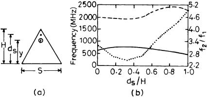
A coaxial probe-fed ETMSA with a single short is shown in Figure 7.27(a) [39]. The ETMSA of side length S = 5 cm is fabricated on the substrate having er = 4.4 and h = 0.16 cm. The resonance frequency of the ETMSA for the fundamental TM10 mode without any shorting post is 1.90 GHz. The position d s of the single shorting post of radius = 0.032 cm is varied along the line from the vertex to the base of the patch. The optimal feed position for the impedance matching is within a few millimeters of the shorting post. The variation of f 1, f 2, and f 2 /f 1 with d s /H is shown in Figure 7.27(b). When d s /H is increased from 0 to 1, the ratio f 2 /f 1 varies between 2.5 and 4.9. The frequency ratio is maximum when the shorting post is close to the tip of the triangle and is minimum when the short is at d s /H = 0.33, which corresponds to the null position for the fundamental TM10 mode of the ETMSA.
A general design guideline can be drawn from the above MSA configurations with a single shorting post. When an f 2 /f 1 ratio of 2 to 3.2 is required, then an RMSA with a single shorting post may be used. For a slightly larger ratio of 2.6 to 3.8, a CMSA with a single short is desirable. Finally, for a
Figure 7.27 (a) ETMSA with a single shorting post for dual-band operation and (b) variation of resonance frequencies with the location of the shorting post ds /H : ( —— ) f 1, ( - - - ) f 2, and ( ? ? ? ) f 2 /f 1.