


§11.2 A framework for digital signature mechanisms |
427 |
This chapter is, for the most part, concerned simply with digital signature schemes. In order to use a digital signature scheme in practice, it is necessary to have a digital signature process. Several processes related to various schemes have emerged as commercially relevant standards; two such processes, namely ISO/IEC 9796 and PKCS #1, are described in §11.3.5 and §11.3.6, respectively. Notation used in the remainder of this chapter is provided in Table 11.1. The sets and functions listed in Table 11.1 are all publicly known.
Notation |
Meaning |
|
|
M |
a set of elements called the message space. |
MS |
a set of elements called the signing space. |
S |
a set of elements called the signature space. |
R |
a 1 − 1 mapping from M to MS called the redundancy function. |
MR |
the image of R (i.e., MR = Im(R)). |
R−1 |
the inverse of R (i.e., R−1 : MR −→ M). |
R |
a set of elements called the indexing set for signing. |
h |
a one-way function with domain M. |
Mh |
the image of h (i.e., h: M −→ Mh); Mh MS called the |
|
hash value space. |
|
Table 11.1: Notation for digital signature mechanisms. |
11.1Note (comments on Table 11.1)
(i)(messages) M is the set of elements to which a signer can affix a digital signature.
(ii)(signing space) MS is the set of elements to which the signature transformations (to be described in §11.2.2 and §11.2.3) are applied. The signature transformations are not applied directly to the set M.
(iii)(signature space) S is the set of elements associated to messages in M. These elements are used to bind the signer to the message.
(iv)(indexing set) R is used to identify specific signing transformations.
A classification of digital signature schemes
§11.2.2 and §11.2.3 describe two general classes of digital signature schemes, which can be briefly summarized as follows:
1.Digital signature schemes with appendix require the original message as input to the verification algorithm. (See Definition 11.3.)
2.Digital signature schemes with message recovery do not require the original message as input to the verification algorithm. In this case, the original message is recovered from the signature itself. (See Definition 11.7.)
These classes can be further subdivided according to whether or not |R| = 1, as noted in Definition 11.2.
11.2Definition A digital signature scheme (with either message recovery or appendix) is said to be a randomized digital signature scheme if |R| > 1; otherwise, the digital signature scheme is said to be deterministic.
Figure 11.1 illustrates this classification. Deterministic digital signature mechanisms can be further subdivided into one-time signature schemes (§11.6) and multiple-use schemes.

428 |
Ch. 11 Digital Signatures |
Randomized
message recovery
Deterministic
Digital signature schemes
Randomized
appendix
Deterministic
Figure 11.1: A taxonomy of digital signature schemes.
11.2.2 Digital signature schemes with appendix
Digital signature schemes with appendix, as discussed in this section, are the most commonly used in practice. They rely on cryptographic hash functions rather than customized redundancy functions, and are less prone to existential forgery attacks (§11.2.4).
11.3Definition Digital signature schemes which require the message as input to the verification algorithm are called digital signature schemes with appendix.
Examples of mechanisms providing digital signatures with appendix are the DSA (§11.5.1), ElGamal (§11.5.2), and Schnorr (§11.5.3) signature schemes. Notation for the following discussion is given in Table 11.1.
11.4Algorithm Key generation for digital signature schemes with appendix
SUMMARY: each entity creates a private key for signing messages, and a corresponding public key to be used by other entities for verifying signatures.
1.Each entity A should select a private key which defines a set SA = {SA,k : k R} of transformations. Each SA,k is a 1-1 mapping from Mh to S and is called a signing transformation.
2.SA defines a corresponding mapping VA from Mh × S to {true, false} such that
|
true, |
|
|
if SA,k(m) = s , |
|
VA(m,s ) = false, |
otherwise, |
|
for all m Mh, s S; here, m = h(m) for m M. VA is called a verification transformation and is constructed such that it may be computed without knowledge of the signer’s private key.
3. A’s public key is VA; A’s private key is the set SA.

§11.2 A framework for digital signature mechanisms |
429 |
11.5Algorithm Signature generation and verification (digital signature schemes with appendix)
SUMMARY: entity A produces a signature s S for a message m M, which can later be verified by any entity B.
1.Signature generation. Entity A should do the following:
(a)Select an element k R.
(b)Compute m = h(m) and s = SA,k(m).
(c)A’s signature for m is s . Both m and s are made available to entities which may wish to verify the signature.
2.Verification. Entity B should do the following:
(a)Obtain A’s authentic public key VA.
(b)Compute m = h(m) and u = VA(m,s ).
(c)Accept the signature if and only if u = true.
Figure 11.2 provides a schematic overview of a digital signature scheme with appendix. The following properties are required of the signing and verification transformations:
(i)for each k R, SA,k should be efficient to compute;
(ii)VA should be efficient to compute; and
(iii)it should be computationally infeasible for an entity other than A to find an m M and an s S such that VA(m,s ) = true, where m = h(m).
M |
Mh |
S |
h |
m |
SA,k |
m |
s = SA,k(m) |
|
|
|
|
(a) The signing process
Mh ×S |
VA |
true |
|
|
|
|
|
false |
(b) The verification process
Figure 11.2: Overview of a digital signature scheme with appendix.
11.6Note (use of hash functions) Most digital signature schemes with message recovery (§11.2.3) are applied to messages of a fixed length, while digital signatures with appendix are applied to messages of arbitrary length. The one-way function h in Algorithm 11.5 is

430 |
Ch. 11 Digital Signatures |
typically selected to be a collision-free hash function (see Definition 9.3). An alternative to hashing is to break the message into blocks of a fixed length which can be individually signed using a signature scheme with message recovery. Since signature generation is relatively slow for many schemes, and since reordering of multiple signed blocks presents a security risk, the preferred method is to hash.
11.2.3 Digital signature schemes with message recovery
The digital signature schemes described in this section have the feature that the message signed can be recovered from the signature itself. In practice, this feature is of use for short messages (see §11.3.3(viii)).
11.7Definition A digital signature scheme with message recovery is a digital signature scheme for which a priori knowledge of the message is not required for the verification algorithm.
Examples of mechanisms providing digital signatures with message recovery are RSA (§11.3.1), Rabin (§11.3.4), and Nyberg-Rueppel (§11.5.4) public-key signature schemes.
11.8 Algorithm Key generation for digital signature schemes with message recovery
SUMMARY: each entity creates a private key to be used for signing messages, and a corresponding public key to be used by other entities for verifying signatures.
1. Each entity A should select a set SA = {SA,k : k R} of transformations. Each SA,k is a 1-1 mapping from MS to S and is called a signing transformation.
2. SA defines a corresponding mapping VA with the property that VA ◦SA,k is the identity map on MS for all k R. VA is called a verification transformation and is constructed such that it may be computed without knowledge of the signer’s private key.
3. A’s public key is VA; A’s private key is the set SA.
11.9 Algorithm Signature generation and verification for schemes with message recovery
SUMMARY: entity A produces a signature s S for a message m M, which can later be verified by any entity B. The message m is recovered from s.
1. Signature generation. Entity A should do the following:
(a) Select an element k R.
(b) Compute m = R(m) and s = SA,k(m). (R is a redundancy function; see Table 11.1 and Note 11.10.)
(c) A’s signature is s ; this is made available to entities which may wish to verify the signature and recover m from it.
2. Verification. Entity B should do the following:
(a) Obtain A’s authentic public key VA.
(b) Compute m = VA(s ).
(c) Verify that m M . (If m M, then reject the signature.)
R R
(d) Recover m from m by computing R−1(m).

§11.2 A framework for digital signature mechanisms |
431 |
M |
R |
MR |
S |
|
|
SA,k |
|
m |
|
m |
s = SA,k(m) |
|
|
MS |
|
Figure 11.3: Overview of a digital signature scheme with message recovery.
Figure 11.3 provides a schematic overview of a digital signature scheme with message recovery. The following properties are required of the signing and verification transformations:
(i)for each k R, SA,k should be efficient to compute;
(ii)VA should be efficient to compute; and
(iii)it should be computationally infeasible for an entity other than A to find any s S such that VA(s ) MR.
11.10Note (redundancy function) The redundancy function R and its inverse R−1 are publicly known. Selecting an appropriate R is critical to the security of the system. To illustrate
this point, suppose that MR = MS. Suppose R and SA,k are bijections from M to MR
and MS to S, respectively. This implies that M and S have the same number of elements. Then for any s S,VA(s ) MR, and it is trivial to find messages m and corresponding signatures s which will be accepted by the verification algorithm (step 2 of Algorithm 11.9)
as follows.
1.Select random k R and random s S.
2.Compute m = VA(s ).
3.Compute m = R−1(m).
The element s is a valid signature for the message m and was created without knowledge of the set of signing transformations SA.
11.11Example (redundancy function) Suppose M = {m: m {0,1}n} for some fixed positive integer n and MS = {t: t {0,1}2n}. Define R: M −→ MS by R(m) = m m, where denotes concatenation; that is, MR = {m m: m M} MS. For large val-
ues of n, the quantity |MR|/|MS| = ( 12 )n is a negligibly small fraction. This redundancy function is suitable provided that no judicious choice of s on the part of an adversary will have a non-negligible probability of yielding VA(s ) MR.
11.12Remark (selecting a redundancy function) Even though the redundancy function Ris public knowledge and R−1 is easy to compute, selection of R is critical and should not be made independently of the choice of the signing transformations in SA. Example 11.21 provides a specific example of a redundancy function which compromises the security of the signature scheme. An example of a redundancy function which has been accepted as an international standard is given in §11.3.5. This redundancy function is not appropriate for all digital signature schemes with message recovery, but does apply to the RSA (§11.3.1) and Rabin (§11.3.4) digital signature schemes.

432 |
Ch. 11 Digital Signatures |
11.13Remark (a particular class of message recovery schemes) §1.8.3 describes a class of digital signature schemes with message recovery which arise from reversible public-key encryption methods. Examples include the RSA (§8.2) and Rabin (§8.3) encryption schemes. The corresponding signature mechanisms are discussed in §11.3.1 and §11.3.4, respectively.
11.14Note (signatures with appendix from schemes providing message recovery) Any digital signature scheme with message recovery can be turned into a digital signature scheme with appendix by simply hashing the message and then signing the hash value. The message is now required as input to the verification algorithm. A schematic for this situation can be derived from Figure 11.3 and is illustrated in Figure 11.4. The redundancy function R is no longer critical to the security of the signature scheme, and can be any 1 − 1 function from Mh to MS.
M |
Mh |
R |
MR |
S |
h |
|
|
SA,k |
|
|
|
|
m |
|
m |
h(m) |
|
|
s = SA,k(m) |
|
|
|
MS |
|
Figure 11.4: Signature scheme with appendix obtained from one providing message recovery.
11.2.4 Types of attacks on signature schemes
The goal of an adversary is to forge signatures; that is, produce signatures which will be accepted as those of some other entity. The following provides a set of criteria for what it means to break a signature scheme.
1.total break. An adversary is either able to compute the private key information of the signer, or finds an efficient signing algorithm functionally equivalent to the valid signing algorithm. (For example, see §11.3.2(i).)
2.selective forgery. An adversary is able to create a valid signature for a particular message or class of messages chosen a priori. Creating the signature does not directly involve the legitimate signer. (See Example 11.21.)
3.existential forgery. An adversary is able to forge a signature for at least one message. The adversary has little or no control over the message whose signature is obtained, and the legitimate signer may be involved in the deception (for example, see Note 11.66(iii)).
There are two basic attacks against public-key digital signature schemes.
1.key-only attacks. In these attacks, an adversary knows only the signer’s public key.
2.message attacks. Here an adversary is able to examine signatures corresponding either to known or chosen messages. Message attacks can be further subdivided into three classes:
(a)known-message attack. An adversary has signatures for a set of messages which are known to the adversary but not chosen by him.

§11.3 RSA and related signature schemes |
433 |
(b)chosen-message attack. An adversary obtains valid signatures from a chosen list of messages before attempting to break the signature scheme. This attack is non-adaptive in the sense that messages are chosen before any signatures are seen. Chosen-message attacks against signature schemes are analogous to chosen-ciphertext attacks against public-key encryption schemes (see §1.13.1).
(c)adaptive chosen-message attack. An adversary is allowed to use the signer as an oracle; the adversary may request signatures of messages which depend on the signer’s public key and he may request signatures of messages which depend on previously obtained signatures or messages.
11.15Note (adaptive chosen-message attack) In principle, an adaptive chosen-message attack is the most difficult type of attack to prevent. It is conceivable that given enough messages and corresponding signatures, an adversary could deduce a pattern and then forge a signature of its choice. While an adaptive chosen-message attack may be infeasible to mount in practice, a well-designed signature scheme should nonetheless be designed to protect against the possibility.
11.16Note (security considerations) The level of security required in a digital signature scheme may vary according to the application. For example, in situations where an adversary is only capable of mounting a key-only attack, it may suffice to design the scheme to prevent the adversary from being successful at selective forgery. In situations where the adversary is capable of a message attack, it is likely necessary to guard against the possibility of existential forgery.
11.17Note (hash functions and digital signature processes) When a hash function h is used in a digital signature scheme (as is often the case), h should be a fixed part of the signature process so that an adversary is unable to take a valid signature, replace h with a weak hash function, and then mount a selective forgery attack.
11.3RSA and related signature schemes
This section describes the RSA signature scheme and other closely related methods. The security of the schemes presented here relies to a large degree on the intractability of the integer factorization problem (see §3.2). The schemes presented include both digital signatures with message recovery and appendix (see Note 11.14).
11.3.1 The RSA signature scheme
The message space and ciphertext space for the RSA public-key encryption scheme (§8.2) are both Zn = {0,1,2,... ,n − 1} where n = pq is the product of two randomly chosen distinct prime numbers. Since the encryption transformation is a bijection, digital signatures can be created by reversing the roles of encryption and decryption. The RSA signature scheme is a deterministic digital signature scheme which provides message recovery (see Definition 11.7). The signing space MS and signature space S are both Zn (see Table 11.1 for notation). A redundancy function R: M −→ Zn is chosen and is public knowledge.

434 |
Ch. 11 Digital Signatures |
11.18Algorithm Key generation for the RSA signature scheme
SUMMARY: each entity creates an RSA public key and a corresponding private key. Each entity A should do the following:
1.Generate two large distinct random primes p and q, each roughly the same size (see §11.3.2).
2.Compute n = pq and φ = (p − 1)(q − 1).
3.Select a random integer e, 1 < e < φ, such that gcd(e,φ) = 1.
4.Use the extended Euclidean algorithm (Algorithm 2.107) to compute the unique integer d, 1 < d < φ, such that ed ≡ 1 (mod φ).
5.A’s public key is (n,e); A’s private key is d.
11.19Algorithm RSA signature generation and verification
SUMMARY: entity A signs a message m M. Any entity B can verify A’s signature and recover the message m from the signature.
1.Signature generation. Entity A should do the following:
(a)Compute m = R(m), an integer in the range [0,n − 1].
(b)Compute s = md mod n.
(c)A’s signature for m is s.
2.Verification. To verify A’s signature s and recover the message m, B should:
(a)Obtain A’s authentic public key (n,e).
(b)Compute m = se mod n.
(c)Verify that m MR; if not, reject the signature.
(d)Recover m = R−1(m).
Proof that signature verification works. If s is a signature for a message m, then s ≡ md mod n where m = R(m). Since ed ≡ 1 (mod φ), se ≡ med ≡ m (mod n). Finally, R−1(m) = R−1(R(m)) = m.
11.20Example (RSA signature generation with artificially small parameters)
Key generation. Entity A selects primes p = 7927, q = 6997, and computes n = pq = 55465219 and φ = 7926 × 6996 = 55450296. A chooses e = 5 and solves ed = 5d ≡ 1 (mod 55450296), yielding d = 44360237. A’s public key is (n = 55465219,e = 5);
A’s private key is d = 44360237.
Signature generation. For the sake of simplicity (but see §11.3.3(ii)), assume that M = Zn and that the redundancy function R: M −→ Zn is the identity map R(m) = m for all m M. To sign a message m = 31229978, A computes m = R(m) = 31229978, and computes the signature s = md mod n = 3122997844360237 mod 55465219 = 30729435.
Signature verification. B computes m = se mod n = 307294355 mod 55465219 =
31229978. Finally, B accepts the signature since m has the required redundancy (i.e., m
MR), and recovers m = R−1 |
|
|
|
(m) = 31229978. |
11.3.2 Possible attacks on RSA signatures
(i) Integer factorization
If an adversary is able to factor the public modulus n of some entity A, then the adversary can compute φand then, using the extended Euclidean algorithm (Algorithm 2.107), deduce
§11.3 RSA and related signature schemes |
435 |
the private key d from φ and the public exponent e by solving ed ≡ 1 (mod φ). This constitutes a total break of the system. To guard against this, A must select p and q so that factoring n is a computationally infeasible task. For further information, see §8.2.2(i) and Note 8.8.
(ii) Multiplicative property of RSA
The RSA signature scheme (as well as the encryption method, cf. §8.2.2(v)) has the following multiplicative property, sometimes referred to as the homomorphic property. If s1 = md1 mod n and s2 = md2 mod n are signatures on messages m1 and m2, respectively (or more properly on messages with redundancy added), then s = s1s2 mod n has the property that s = (m1m2)d mod n. If m = m1m2 has the proper redundancy (i.e., m MR), then s will be a valid signature for it. Hence, it is important that the redundancy function R is not multiplicative, i.e., for essentially all pairs a,b M, R(a · b) =R(a)R(b). As Example 11.21 shows, this condition on R is necessary but not sufficient for security.
11.21Example (insecure redundancy function) Let n be an RSA modulus and d the private key.
Let k = lg n be the bitlength of n, and let t be a fixed positive integer such that t < k/2. Let w = 2t and let messages be integers m in the interval [1,n2−t − 1]. The redundancy function R is taken to be R(m) = m2t (the least significant t bits of the binary representation of R(m) are 0’s). For most choices of n, R will not have the multiplicative property.
The general existential forgery attack described in Note 11.10 would have a probability of
success of (12 )t. But for this redundancy function, a selective forgery attack (which is more serious) is possible, as is now explained.
Suppose that an adversary wishes to forge a signature on a message m. The adversary knows n but not d. The adversary can mount the following chosen-message attack to obtain the signature on m. Apply the extended Euclidean algorithm (Algorithm 2.107) to n and m = R(m) = m2t = mw. At each stage of the extended Euclidean algorithm, integers
x, y, and r are computed such that xn + ym = r. It can be shown that√at some stage there |
||||||||||
exists a y |
|
r |
|
|y| < n/w and |
|
≤ |
|
|
0 |
|
|
and |
|
such that |
|
r < n/w, provided w |
|
n. If y > |
|
, form |
|
integers m2 = rw and m3 = yw. If y < 0, form integers m2 = rw and m3 = −yw. In either case, m2 and m3 have the required redundancy. If signatures s2 = md2 mod n and
s3 |
= md mod n are obtained from the legitimate signer, then the adversary can compute a |
|||||||||||
|
3 |
|
|
|
|
|
|
|
|
|
|
|
signature for m as follows: |
|
|
|
|
|
|
|
|
|
|||
|
|
|
|
|
d |
|
|
|
|
|
|
|
|
• if y > 0, compute |
s2 = |
m2 |
= ( rw )d = ( r )d = md mod n; |
||||||||
|
d |
|||||||||||
|
|
s3 |
|
m |
|
yw |
y |
= ( r )d = md mod n. |
||||
|
|
|
|
|
3 |
|
|
|
|
|||
|
• if y < 0, compute |
s2 |
= |
|
m2d |
|
= ( rw )d |
|||||
|
−s3 |
(−m3) |
d |
|||||||||
|
|
|
|
|
|
yw |
y |
choice with the required redun- |
||||
In either case, the adversary has a signed message of its |
||||||||||||
|
||||||||||||
dancy. This attack is an example of a chosen-message attack providing selective forgery. It emphasizes the requirement for judicious choice of the redundancy function R.
11.3.3 RSA signatures in practice
(i) Reblocking problem
One suggested use of RSA is to sign a message and then encrypt the resulting signature. One must be concerned about the relative sizes of the moduli involved when implementing this procedure. Suppose that A wishes to sign and then encrypt a message for B. Suppose that (nA,eA) and (nB,eB) are A’s and B’s public keys, respectively. If nA > nB, then there is a chance that the message cannot be recovered by B, as illustrated in Example 11.22.
436 |
Ch. 11 Digital Signatures |
11.22Example (reblocking problem) Let nA = 8387 × 7499 = 62894113, eA = 5, and dA = 37726937; and nB = 55465219, eB = 5, dB = 44360237. Notice that nA > nB. Suppose m = 1368797 is a message with redundancy to be signed under A’s private key and then encrypted using B’s public key. A computes the following:
1.s = mdA mod nA = 136879737726937 mod 62894113 = 59847900.
2.c = seB mod nB = 598479005 mod 55465219 = 38842235.
To recover the message and verify the signature, B computes the following:
1.s = cdB mod nB = 3884223544360237 mod 55465219 = 4382681.
2.m = seA mod nA = 43826815 mod 62894113 = 54383568.
Observe that m =m. The reason for this is that s is larger than the modulus nB. Here, the
probability of this |
problem occurring is |
|
n |
A − |
n |
/n |
. . |
|
|
( |
|
|
B) |
A ≈ 0 12 |
There are various ways to overcome the reblocking problem.
1.reordering. The problem of incorrect decryption will never occur if the operation using the smaller modulus is performed first. That is, if nA > nB, then entity A should first encrypt the message using B’s public key, and then sign the resulting ciphertext using A’s private key. The preferred order of operations, however, is always to sign the message first and then encrypt the signature; for if A encrypts first and then signs, an adversary could remove the signature and replace it with its own signature. Even though the adversary will not know what is being signed, there may be situations where this is advantageous to the adversary. Thus, reordering is not a prudent solution.
2.two moduli per entity. Have each entity generate separate moduli for encrypting and for signing. If each user’s signing modulus is smaller than all of the possible encrypting moduli, then incorrect decryption never occurs. This can be guaranteed by requiring encrypting moduli to be (t + 1)-bit numbers and signing moduli t-bit numbers.
3.prescribing the form of the modulus. In this method, one selects the primes p and q so that the modulus n has a special form: the highest-order bit is a 1 and the k following bits are all 0’s. A t-bit modulus n of this form can be found as follows. For n to have
the required form, 2t−1 ≤ n < 2t−1 + 2t−k−1. Select a random t/2 -bit prime p, and search for a prime q in the interval between 2t−1/p and (2t−1 + 2t−k−1)/p ; then n = pq is a modulus of the required type (see Example 11.23). This choice for the modulus n does not completely prevent the incorrect decryption problem, but it can reduce the probability of its occurrence to a negligibly small number. Suppose that nA is such a modulus and s = mdA mod nA is a signature on m. Suppose further that s has a 1 in one of the high-order k + 1 bit positions, other than the highest. Then s, since it is smaller than nA, must have a 0 in the highest-order bit position and so is necessarily smaller than any other modulus of a similar form. The probability that s does not have any 1’s in the high-order k+ 1 bit positions, other than the highest, is less than (12 )k, which is negligibly small if k is selected to be around 100.
11.23 Example (prescribing the form of the modulus) Suppose one wants to construct a 12-bit modulus n such that the high order bit is a 1 and the next k = 3 bits are 0’s. Begin by selecting a 6-bit prime p = 37. Select a prime q in the interval between 211/p = 56 and(211 + 28)/p = 62. The possibilities for q are 59 and 61. If q = 59 is selected, then n = 37 × 59 = 2183, having binary representation 100010000111. If q = 61 is selected, then n = 37 × 61 = 2257, having binary representation 100011010001.


438 |
Ch. 11 Digital Signatures |
efficiency in this case is 12 . For example, with a modulus of size 1024 bits, the maximum size of a message which can be signed is 512 bits.
(vii) System-wide parameters
Each entity must have a distinct RSA modulus; it is insecure to use a system-wide modulus (see §8.2.2(vi)). The public exponent e can be a system-wide parameter, and is in many applications (see Note 8.9(ii)).
(viii) Short vs. long messages
Suppose n is a 2k-bit RSA modulus which is used in Algorithm 11.19 to sign k-bit messages (i.e., the bandwidth efficiency is 12 ). Suppose entity A wishes to sign a kt-bit message m. One approach is to partition m into k-bit blocks such that m = m1||m2||···||mt and sign each block individually (but see Note 11.6 regarding why this is not recommended). The bandwidth requirement for this is 2kt bits. Alternatively, A could hash message m to a bitstring of length l ≤ k and sign the hash value. The bandwidth requirement for this signature is kt+2k, where the term kt comes from sending the message m. Since kt+2k ≤ 2kt whenever t ≥ 2, it follows that the most bandwidth efficient method is to use RSA digital signatures with appendix. For a message of size at most k-bits, RSA with message recovery is preferred.
11.3.4 The Rabin public-key signature scheme
The Rabin public-key signature scheme is similar to RSA (Algorithm 11.19), but it uses an even public exponent e. 3 For the sake of simplicity, it will be assumed that e = 2. The signing space MS is Qn (the set of quadratic residues modulo n — see Definition 2.134) and signatures are square roots of these. A redundancy function R from the message space M to MS is selected and is public knowledge.
Algorithm 11.25 describes the basic version of the Rabin public-key signature scheme. A more detailed version (and one more useful in practice) is presented in Algorithm 11.30.
11.24Algorithm Key generation for the Rabin public-key signature scheme
SUMMARY: each entity creates a public key and corresponding private key. Each entity A should do the following:
1.Generate two large distinct random primes p and q, each roughly the same size.
2.Compute n = pq.
3.A’s public key is n; A’s private key is (p,q).
11.25Algorithm Rabin signature generation and verification
SUMMARY: entity A signs a message m M. Any entity B can verify A’s signature and recover the message m from the signature.
1.Signature generation. Entity A should do the following:
(a)Compute m = R(m).
(b)Compute a square root s of m mod n (using Algorithm 3.44).
(c)A’s signature for m is s.
3Since p and q are distinct primes in an RSA modulus, φ = (p − 1)(q − 1) is even. In RSA, the public exponent e must satisfy gcd(e,φ) = 1 and so must be odd.

§11.3 RSA and related signature schemes |
439 |
2.Verification. To verify A’s signature s and recover the message m, B should:
(a)Obtain A’s authentic public key n.
(b)Compute m = s2 mod n.
(c)Verify that m MR; if not, reject the signature.
(d)Recover m = R−1(m).
11.26Example (Rabin signature generation with artificially small parameters)
Key generation. Entity A selects primes p = 7, q = 11, and computes n = 77. A’s public key is n = 77; A’s private key is (p = 7,q = 11). The signing space is MS =
Q77 = {1,4,9,15,16,23,25,36,37,53,58,60,64,67,71}. For the sake of simplicity (but see Note 11.27), take M = MS and the redundancy function R to be the identity map (i.e., m = R(m) = m).
Signature generation. To sign a message m = 23, A computes R(m) = m = 23, and then finds a square root of m modulo 77. If s denotes such a square root, then s ≡ ±3 (mod 7) and s ≡ ±1 (mod 11), implying s = 10, 32, 45, or 67. The signature for m is chosen to be s = 45. (The signature could be any one of the four square roots.)
Signature verification. B computes m = s2 mod 77 = 23. Since m = 23 MR, B
accepts the signature and recovers m = R−1(m) = 23. |
|
11.27Note (redundancy)
(i)As with the RSA signature scheme (Example 11.21), an appropriate choice of a redundancy function R is crucial to the security of the Rabin signature scheme. For
example, suppose that M = MS = Qn and R(m) = m for all m M. If an adversary selects any integer s Zn and squares it to get m = s2 mod n, then s is a valid signature for m and is obtained without knowledge of the private key. (Here,
the adversary has little control over what the message will be.) In this situation, existential forgery is trivial.
(ii)In most practical applications of digital signature schemes with message recovery, the message space M consists of bitstrings of some fixed length. For the Rabin scheme, determining a redundancy function Ris a challenging task. For example, if a message m is a bitstring, R might assign it to the integer whose binary representation is the message. There is, however, no guarantee that the resulting integer is a quadratic residue modulo n, and so computing a square root might be impossible. One might try to append a small number of random bits to m and apply R again in the hope that R(m) Qn. On average, two such attempts would suffice, but a deterministic method would be preferable.
Modified-Rabin signature scheme
To overcome the problem discussed in Note 11.27(ii), a modified version of the basic Rabin signature scheme is provided. The technique presented is similar to that used in the ISO/IEC 9796 digital signature standard (§11.3.5). It provides a deterministic method for associating messages with elements in the signing space MS, such that computing a square root (or something close to it) is always possible. An understanding of this method will facilitate the reading of §11.3.5.
11.28Fact Let p and q be distinct primes each congruent to 3 modulo 4, and let n = pq.
(i)If gcd(x,n) = 1, then x(p−1)(q−1)/2 ≡ 1 (mod n).
(ii)If x Qn, then x(n−p−q+5)/8 mod n is a square root of x modulo n.

440 |
|
|
|
|
|
Ch. 11 Digital Signatures |
|||||||
(iii) |
Then |
|
n = 1 |
, and let d |
= ( |
− |
p |
− |
q |
+ 5) 8 |
. |
||
|
Let x be an integer having Jacobi symbol x |
|
n |
|
|
/ |
|||||||
|
|
|
|
x, if x Qn, |
|
|
|
|
|
|
|
||
|
|
x2d mod n = n − x, |
if x Qn. |
|
|
|
|
|
|
|
|||
(iv) |
If p ≡q (mod 8), then |
2 |
= −1. Hence, multiplication of any integer x by 2 or |
||||||||||
|
−1 |
|
n |
|
|
|
|
|
|
|
|
|
|
|
|
Jacobi symbol of x. (Integers of the form n |
= |
pq where |
|||||||||
|
2 mod n reverses the |
|
|
|
|
|
|
|
|
||||
p ≡ q ≡ 3 (mod 4) and p ≡q (mod 8) are sometimes called Williams integers.)
Algorithm 11.30 is a modified version of the Rabin digital signature scheme. Messages to be signed are from MS = {m Zn : m ≡ 6 (mod 16)}. Notation is given in Table 11.2. In practice, the redundancy function R should be more complex to prevent existential forgery (see §11.3.5 for an example).
Symbol |
Term |
Description |
|
|
|
M |
message space |
{m Zn : m ≤ (n − 6)/16 } |
MS |
signing space |
{m Zn : m ≡ 6 (mod 16)} |
S |
signature space |
{s Zn : (s2 mod n) MS} |
R |
redundancy function |
R(m) = 16m + 6 for all m M |
MR |
image of R |
{m Zn : m ≡ 6 (mod 16)} |
Table 11.2: Definition of sets and functions for Algorithm 11.30.
11.29Algorithm Key generation for the modified-Rabin signature scheme
SUMMARY: each entity creates a public key and corresponding private key. Each entity A should do the following:
1.Select random primes p ≡ 3 (mod 8), q ≡ 7 (mod 8) and compute n = pq.
2.A’s public key is n; A’s private key is d = (n − p − q + 5)/8.
11.30Algorithm Modified-Rabin public-key signature generation and verification
SUMMARY: entity A signs a message m M. Any entity B can verify A’s signature and recover the message m from the signature.
1.Signature generation. Entity A should do the following:
(a) Compute m = R(m) = 16m + 6.
(b) Compute the Jacobi symbol J = mn (using Algorithm 2.149).
(c)If J = 1 then compute s = md mod n.
(d)If J = −1 then compute s = (m/2)d mod n. 4
(e)A’s signature for m is s.
2.Verification. To verify A’s signature s and recover the message m, B should:
(a)Obtain A’s authentic public key n.
(b)Compute m = s2 mod n. (Note the original message m itself is not required.)
(c)If m ≡ 6 (mod 8), take m = m .
(d)If m ≡ 3 (mod 8), take m = 2m .
4If J = or1 −1 then J = 0, implying gcd(m,n) =. 1This leads to a factorization of n. In practice, the probability that this will ever occur is negligible.

§11.3 RSA and related signature schemes |
441 |
(e)If m ≡ 7 (mod 8), take m = n − m .
(f)If m ≡ 2 (mod 8), take m = 2(n − m ).
(g)Verify that m MR (see Table 11.2); if not, reject the signature.
(h)Recover m = R−1(m) = (m − 6)/16.
Proof that signature verification works. The signature generation phase signs either v = m or v = m/2 depending upon which has Jacobi symbol 1. By Fact 11.28(iv), exactly one of m, m/2 has Jacobi symbol 1. The value v that is signed is such that v ≡ 3 or 6 (mod 8). By Fact 11.28(iii), s2 mod n = v or n − v depending on whether or not v Qn. Since n ≡ 5 (mod 8), these cases can be uniquely distinguished.
11.31 Example (modified-Rabin signature scheme with artificially small parameters)
Key generation. A chooses p = 19, q = 31, and computes n = pq = 589 and d = (n − p − q + 5)/8 = 68. A’s public key is n = 589, while A’s private key is d = 68. The signing space MS is given in the following table, along with the Jacobi symbol of each element.
|
|
|
|
|
|
m |
|
6 |
|
|
22 |
54 |
70 |
|
86 |
102 |
118 |
134 |
150 |
166 |
|
|
|
|
||||
|
|
|
|
|
m |
|
|
|
−1 |
|
|
1 |
−1 |
−1 |
|
|
1 |
|
1 |
1 |
1 |
−1 |
1 |
|
|
|
|
|
|
|
|
|
|
|
|
|
|
|
|
|
|
|
|
||||||||||||||
|
|
|
|
|
589 |
|
|
|
|
|
|
|
|
|
|
|
|
|
|
|
|
|
|
|
|
|
||
|
|
|
|
|
|
m |
|
182 |
|
198 |
214 |
230 |
|
246 |
262 |
278 |
294 |
326 |
358 |
|
|
|
|
|||||
|
|
|
|
|
m |
|
|
|
−1 |
|
|
1 |
1 |
1 |
|
|
1 |
−1 |
1 |
−1 |
−1 |
−1 |
|
|
|
|
||
|
|
|
|
|
|
|
|
|
|
|
|
|
|
|
||||||||||||||
|
|
|
|
|
589 |
|
|
|
|
|
|
|
|
|
|
|
|
|
|
|
|
|
|
|
|
|
||
|
|
|
|
|
|
m |
|
374 |
|
390 |
406 |
422 |
|
438 |
454 |
470 |
486 |
502 |
518 |
|
|
|
|
|||||
|
|
|
|
|
m |
|
|
|
−1 |
|
−1 |
−1 |
1 |
|
|
1 |
|
1 |
−1 |
−1 |
1 |
−1 |
|
|
|
|
||
|
|
|
|
|
|
|
|
|
|
|
|
|
|
|
||||||||||||||
|
|
|
|
|
589 |
|
|
|
|
|
|
|
|
|
|
|
|
|
|
|
|
|
|
|
|
|
||
|
|
|
|
|
|
m |
|
534 |
|
550 |
566 |
582 |
|
|
|
|
|
|
|
|
|
|
|
|
|
|||
|
|
|
|
|
m |
|
|
|
−1 |
|
|
1 |
−1 |
1 |
|
|
|
|
|
|
|
|
|
|
|
|
|
|
|
|
|
|
|
|
|
|
|
|
|
|
|
|
|
|
|
|
|
|
|
|
|||||||
|
|
|
|
|
589 |
|
|
|
|
|
|
|
|
|
|
|
|
|
|
|
|
|
|
|
|
= |
||
|
|
|
|
|
|
|
|
|
|
|
|
|
|
|
|
|
|
|
|
|
|
|
|
|
|
|
m |
|
Signature generation. To sign a message m = 12, A computes m = R(12) = 198, n |
||||||||||||||||||||||||||||
198 |
|
= 1, and s = 198 |
68 |
mod 589 = 102 |
A2 |
|
|
|
2 = 12 |
is s |
= 102 |
. |
|
|
|
|||||||||||||
589 |
|
|
|
|
|
|
|
|
||||||||||||||||||||
|
|
|
|
|
|
|
|
|
|
|
|
|
|
|
|
. |
|
’s signature for m |
|
|
|
|
||||||
|
|
|
|
|
|
|
|
|
|
|
|
|
|
= |
s |
|
mod |
n |
= 102 |
mod 589 = 391 |
. Since |
|||||||
Signature verification. B computes m |
|
|
|
|
|
|
|
|
|
|||||||||||||||||||
m |
|
≡ 7 (mod 8), B takes m = n − m |
= 589 − 391 = 198. Finally, B computes |
|||||||||||||||||||||||||
m |
= |
R−1 |
( |
|
) = (198 |
− 6) |
|
|
|
|
|
|
|
|
|
|
|
|
|
|
|
|||||||
|
|
|
m |
|
|
|
|
/16 = 12, and accepts the signature. |
|
|
|
|
|
|
||||||||||||||
11.32Note (security of modified-Rabin signature scheme)
(i)When using Algorithm 11.30, one should never sign a value v having Jacobi symbol −1, since this leads to a factorization of n. To see this, observe that y = v2d = s2 must have Jacobi symbol 1; but y2 ≡ (v2)2d ≡ v2 (mod n) by Fact 11.28(iii). Therefore, (v−y)(v+y) ≡ 0 (mod n). Since v and y have opposite Jacobi symbols, v ≡y (mod n) and thus gcd(v − y,n) = p or q.
(ii)Existential forgery is easily accomplished for the modified-Rabin scheme as it was for the original Rabin scheme (see Note 11.27(i)). One only needs to find an s, 1 ≤ s ≤ n − 1, such that either s2 or n − s2 or 2s2 or 2(n − s2) mod n is congruent to 6 modulo 16. In any of these cases, s is a valid signature for m = s2 mod n.
11.33Note (performance characteristics of the Rabin signature scheme) Algorithm 11.25 requires a redundancy function from M to MS = Qn which typically involves computing a Jacobi symbol (Algorithm 2.149). Signature generation then involves computing at least one Jacobi symbol (see Note 11.27) and a square root modulo n. The square root computation is comparable to an exponentiation modulo n (see Algorithm 3.44). Since computing the Jacobi symbol is equivalent to a small number of modular multiplications, Rabin


444 |
Ch. 11 Digital Signatures |
5.signature production. A signature mechanism is used which maps k-bit integers to k-bit integers (and allows message recovery). IR is signed using this mechanism; let s denote the resulting signature.
11.36Note (RSA, Rabin) ISO/IEC 9796 was intended for use with the RSA (Algorithm 11.19)6 and Rabin (Algorithm 11.25)7 digital signature mechanisms. For these particular schemes, signature production is stated more explicitly. Let e be the public exponent for the RSA or Rabin algorithms, n the modulus, and d the private exponent. First form the representative element RR which is: (i) IR if e is odd, or if e is even and the Jacobi symbol of IR (treated as an integer) with respect to the modulus n is 1; (ii) IR/2 if e is even and the Jacobi symbol of IR with respect to n is −1. The signature for m is s = (RR)d mod n. ISO/IEC 9796 specifies that the signature sshould be the lesser of (RR)d mod n and n−((RR)d mod n).
(ii)Verification process for ISO/IEC 9796
The verification process for an ISO/IEC 9796 digital signature can be separated into three stages, as per Figure 11.5(b).
1.signature opening. Let s be the signature. Then the following steps are performed.
(a)Apply the public verification transformation to s to recover an integer IR .
(b)Reject the signature if IR is not a string of k bits with the most significant bit being a 1, or if the least significant nibble does not have value 0110.
2.message recovery. A string MR of 2t bytes is constructed from IR by performing the following steps.
(a)Let X be the least significant k − 1 bits of IR .
(b)If u4 u3 u2 0110 are the four least significant nibbles of X, replace the least significant byte of X by π−1(u4) u2.
(c)MR is obtained by padding X with between 0 and 15 zero bits so that the resulting string has 2t bytes.
The values z and r are computed as follows.
(a)From the 2t bytes of MR , compute the t sums MR2i S(MR2i−1), 1 ≤ i ≤ t. If all sums are 0, reject the signature.
(b)Let z be the smallest value of i for which MR2i S(MR2i−1) =. 0
(c)Let r be the least significant nibble of the sum found in step (b). Reject the signature if the hexadecimal value of r is not between 1 and 8.
From MR , the z-byte string MP is constructed as follows.
(a)MPi = MR2i−1 for 1 ≤ i ≤ z.
(b)Reject the signature if the r − 1 most significant bits of MP are not all 0’s.
(c)Let M be the 8z − r + 1 least significant bits of MP .
3.redundancy checking. The signature s is verified as follows.
(a)From M construct a string MR by applying the message padding, message extension, and message redundancy steps of the signing process.
(b)Accept the signature if and only if the k − 1 least significant bits of MR are equal to the k − 1 least significant bits of MR .
6Since steps 1 through 4 of the signature process describe the redundancy function R, m in step 1a of Algorithm 11.19 is taken to be IR.
7m is taken to be IR in step 1 of Algorithm 11.25.
§11.3 RSA and related signature schemes |
445 |
11.3.6 PKCS #1 formatting
Public-key cryptography standards (PKCS) are a suite of specifications which include techniques for RSA encryption and signatures (see §15.3.6). This subsection describes the digital signature process specified in PKCS #1 (“RSA Encryption Standard”).
The digital signature mechanism in PKCS #1 does not use the message recovery feature of the RSA signature scheme. It requires a hashing function (either MD2, or MD5 — see Algorithm 9.51) and, therefore, is a digital signature scheme with appendix. Table 11.4 lists notation used in this subsection. Capital letters refer to octet strings. If X is an octet string, then Xi is octet i counting from the left.
Symbol |
Meaning |
|
Symbol |
Meaning |
|
|
|
|
|
k |
the length of n in octets (k ≥ 11) |
|
EB |
encryption block |
n |
the modulus, 28(k−1) ≤ n < 28k |
|
ED |
encrypted data |
p, q |
the prime factors of n |
|
octet |
a bitstring of length 8 |
e |
the public exponent |
|
ab |
hexadecimal octet value |
d |
the private exponent |
|
BT |
block type |
M |
message |
|
PS |
padding string |
MD |
message digest |
|
S |
signature |
MD |
comparative message digest |
|
X |
length of X in octets |
Table 11.4: PKCS #1 notation.
(i) PKCS #1 data formatting
The data is an octet string D, where D ≤ k−11. BT is a single octet whose hexadecimal representation is either 00 or 01. PS is an octet string with PS = k−3−D . If BT = 00, then all octets in PS are 00; if BT = 01, then all octets in PS are ff. The formatted data block (called the encryption block) is EB = 00 BT PS 00 D.
11.37Note (data formatting rationale)
(i)The leading 00 block ensures that the octet string EB, when interpreted as an integer, is less than the modulus n.
(ii)If the block type is BT = 00, then either D must begin with a non-zero octet or its length must be known, in order to permit unambiguous parsing of EB.
(iii)If BT = 01, then unambiguous parsing is always possible.
(iv)For the reason given in (iii), and to thwart certain potential attacks on the signature mechanism, BT = 01 is recommended.
11.38Example (PKCS #1 data formatting for particular values) Suppose that n is a 1024-bit
modulus (so k = 128). If D = 20 octets, then PS = 105 octets, and EB = 128 octets.
(ii) Signature process for PKCS #1
The signature process involves the steps as per Figure 11.6(a).
The input to the signature process is the message M, and the signer’s private exponent d and modulus n.
1.message hashing. Hash the message M using the selected message-digest algorithm to get the octet string MD.


§11.4 Fiat-Shamir signature schemes |
447 |
(b)Convert S to an integer s as in step 4 of the signature process.
(c)Reject the signature if s > n.
2.RSA computation. Compute m = se mod n.
3.integer-to-octet-string conversion. Convert m to an octet string EB of length k octets as in step 6 of the signature process.
4.parsing. Parse EB into a block type BT, a padding string PS, and the data D.
(a)Reject the signature if EB cannot be parsed unambiguously.
(b)Reject the signature if BT is not one of 00 or 01.
(c)Reject the signature if PS consists of < 8 octets or is inconsistent with BT.
5.data decoding.
(a)BER-decode D to get a message digest MD and a hash algorithm identifier.
(b)Reject the signature if the hashing algorithm identifier does not identify one of MD2 or MD5.
6.message digesting and comparison.
(a)Hash the message M with the selected message-digest algorithm to get MD .
(b)Accept the signature S on M if and only if MD = MD.
11.4Fiat-Shamir signature schemes
As described in Note 10.30, any identification scheme involving a witness-challenge response sequence can be converted to a signature scheme by replacing the random challenge of the verifier with a one-way hash function. This section describes two signature mechanisms which arise in this way. The basis for this methodology is the Fiat-Shamir identification protocol (Protocol 10.24).
11.4.1 Feige-Fiat-Shamir signature scheme
The Feige-Fiat-Shamir signature scheme is a modification of an earlier signature scheme of Fiat and Shamir, and requires a one-way hash function h: {0,1} −→ {0,1}k for some fixed positive integer k. Here {0,1}k denotes the set of bitstrings of bitlength k, and {0,1} denotes the set of all bitstrings (of arbitrary bitlengths). The method provides a digital signature with appendix, and is a randomized mechanism.
11.39Algorithm Key generation for the Feige-Fiat-Shamir signature scheme
SUMMARY: each entity creates a public key and corresponding private key. Each entity A should do the following:
1.Generate random distinct secret primes p, q and form n = pq.
2.Select a positive integer k and distinct random integers s1,s2,... ,sk Zn.
3.Compute vj = s−j 2 mod n, 1 ≤ j ≤ k.
4.A’s public key is the k-tuple (v1,v2,... ,vk) and the modulus n; A’s private key is the k-tuple (s1,s2,... ,sk).

448 |
Ch. 11 Digital Signatures |
11.40Algorithm Feige-Fiat-Shamir signature generation and verification
SUMMARY: entity Asigns a binary message mof arbitrary length. Any entity B can verify this signature by using A’s public key.
1.Signature generation. Entity A should do the following:
(a)Select a random integer r, 1 ≤ r ≤ n − 1.
(b)Compute u = r2 mod n.
(c)Compute e = (e1,e2,... ,ek) = h(m u); each ei {0,1}.
(d)Compute s = r · kj=1 sejj mod n.
(e)A’s signature for m is (e,s).
2.Verification. To verify A’s signature (e,s) on m, B should do the following:
(a)Obtain A’s authentic public key (v1,v2,... ,vk) and n.
(b)Compute w = s2 · kj=1 vjej mod n.
(c)Compute e = h(m w).
(d)Accept the signature if and only if e = e .
Proof that signature verification works.
k |
|
k |
k |
|
k |
|
|
|
|
|
|
|
|
w ≡ s2 · vej ≡ r2 |
· |
s2ej |
vej ≡ r2 |
· |
(s2vj)ej ≡ r2 |
≡ u (mod n). |
j |
|
j |
j |
|
j |
|
j=1 |
|
j=1 |
j=1 |
|
j=1 |
|
Hence, w = u and therefore e = e .
11.41Example (Feige-Fiat-Shamir signature generation with artificially small parameters)
Key generation. Entity A generates primes p = 3571, q = 4523, and computes n = pq =
16151633. The following table displays the selection of sj (A’s private key) and integers vj (A’s public key) along with intermediate values s−j 1.
|
j |
|
1 |
2 |
3 |
4 |
5 |
|
|
|
|
|
|
|
|
|
|
|
|
|
|
|
|
|
sj |
|
42 |
73 |
85 |
101 |
150 |
s−1 |
mod n |
|
4999315 |
885021 |
6270634 |
13113207 |
11090788 |
j |
|
|
|
|
|
|
|
vj = sj−2 mod n |
|
503594 |
4879739 |
7104483 |
1409171 |
6965302 |
|
Signature generation. Suppose h: {0,1} −→ {0,1}5 is a hash function. A selects a random integer r = 23181 and computes u = r2 mod n = 4354872. To sign message m, A evaluates e = h(m u) = 10110 (the hash value has been contrived for this example). A forms s = rs1s3s4 mod n = (23181)(42)(85)(101) mod n = 7978909; the signature for m is (e = 10110,s = 7978909).
Signature verification. B computes s2 mod n = 2926875 and v1v3v4 mod n = (503594) (7104483)(1409171) mod n = 15668174. B then computes w = s2v1v3v4 mod n = 4354872. Since w = u, it follows that e = h(m w) = h(m u) = e and, hence, B accepts the signature.
11.42Note (security of Feige-Fiat-Shamir signature scheme)
(i)Unlike the RSA signature scheme (Algorithm 11.19), all entities may use the same modulus n (cf. §8.2.2(vi)). In this scenario, a trusted third party (TTP) would need to generate the primes p and q and also public and private keys for each entity.
§11.4 Fiat-Shamir signature schemes |
449 |
(ii)The security of the Feige-Fiat-Shamir scheme is based on the intractability of computing square roots modulo n (see §3.5.2). It has been proven to be secure against an adaptive chosen-message attack, provided that factoring is intractable, h is a random function, and the si’s are distinct.
11.43Note (parameter selection and key storage requirements) If n is a t-bit integer, the private
key constructed in Algorithm 11.39 is kt bits in size. This may be reduced by selecting the random values sj, 1 ≤ j ≤ k, as numbers of bitlength t < t; t , however, should not be chosen so small that guessing the sj is feasible. The public key is (k + 1)t bits in size. For example, if t = 768 and k = 128, then the private key requires 98304 bits and the public key requires 99072 bits.
11.44Note (identity-based Feige-Fiat-Shamir signatures) Suppose a TTP constructs primes p and q and modulus n; the modulus is common to all entities in the system. Algorithm 11.39 can be modified so that the scheme is identity-based. Entity A’s bitstring IA contains in-
formation which identifies A. The TTP computes vj = f(IA j), 1 ≤ j ≤ k, where f is
aone-way hash function from {0,1} to Qn and j is represented in binary, and computes
asquare root sj of vj−1 modulo n, 1 ≤ j ≤ k. A’s public key is simply the identity information IA, while A’s private key (transported securely and secretly by the TTP to A) is the k-tuple (s1,s2,... ,sk). The functions h, f, and the modulus n are system-wide quantities.
This procedure has the advantage that the public key generated in Algorithm 11.39 might be generated from a smaller quantity IA, potentially reducing the storage and transmission cost. It has the disadvantages that the private keys of entities are known to the TTP, and the modulus n is system-wide, making it a more attractive target.
11.45Note (small prime variation of Feige-Fiat-Shamir signatures) This improvement aims to reduce the size of the public key and increase the efficiency of signature verification. Unlike the modification described in Note 11.44, each entity A generates its own modulus nA and
aset of k small primes v1,v2,... ,vk Qn (each prime will require around 2 bytes to represent). Entity A selects one of the square roots sj of vj−1 modulo n for each j, 1 ≤ j ≤ k; these form the private key. The public key consists of nA and the values v1,v2,... ,vk. Verification of signatures proceeds more efficiently since computations are done with much
smaller numbers.
11.46Note (performance characteristics of Feige-Fiat-Shamir signatures) With the RSA scheme and a modulus of length t = 768, signature generation using naive techniques requires, on average, 1152 modular multiplications (more precisely, 768 squarings and 384 multiplications). Signature generation for the Feige-Fiat-Shamir scheme (Algorithm 11.40) requires, on average, k/2 modular multiplications. To sign a message with this scheme, a modulus of length t = 768 and k = 128 requires, on average, 64 modular multiplications, or less than 6% of the work required by a naive implementation of RSA. Signature verification requires only one modular multiplication for RSA if the public exponent is e = 3, and 64 modular multiplications, on average, for Feige-Fiat-Shamir. For applications where signature generation must be performed quickly and key space storage is not limited, the Feige-Fiat-Shamir scheme (or DSA-like schemes — see §11.5) may be preferable to RSA.


452 |
Ch. 11 Digital Signatures |
Gamal signature scheme in §11.5.2. All of the methods discussed in this section are randomized digital signature schemes (see Definition 11.2). All give digital signatures with appendix and can be modified to provide digital signatures with message recovery (see Note 11.14). A necessary condition for the security of all of the signature schemes described in this section is that computing logarithms in Zp be computationally infeasible. This condition, however, is not necessarily sufficient for the security of these schemes; analogously, it remains unproven that RSA signatures are secure even if factoring integers is hard.
11.5.1 The Digital Signature Algorithm (DSA)
In August of 1991, the U.S. National Institute of Standards and Technology (NIST) proposed a digital signature algorithm (DSA). The DSA has become a U.S. Federal Information Processing Standard (FIPS 186) called the Digital Signature Standard (DSS), and is the first digital signature scheme recognized by any government. The algorithm is a variant of the ElGamal scheme (§11.5.2), and is a digital signature scheme with appendix.
The signature mechanism requires a hash function h: {0,1} −→ Zq for some integer q. The DSS explicitly requires use of the Secure Hash Algorithm (SHA-1), given by Algorithm 9.53.
11.54Algorithm Key generation for the DSA
SUMMARY: each entity creates a public key and corresponding private key. Each entity A should do the following:
1.Select a prime number q such that 2159 < q < 2160.
2.Choose t so that 0 ≤ t ≤ 8, and select a prime number p where 2511+64t < p < 2512+64t, with the property that q divides (p − 1).
3.(Select a generator α of the unique cyclic group of order q in Zp.)
3.1Select an element g Zp and compute α = g(p−1)/q mod p.
3.2If α = 1 then go to step 3.1.
4.Select a random integer a such that 1 ≤ a ≤ q − 1.
5.Compute y = αa mod p.
6.A’s public key is (p,q,α,y); A’s private key is a.
11.55Note (generation of DSA primes p and q) In Algorithm 11.54 one must select the prime q first and then try to find a prime p such that q divides (p−1). The algorithm recommended by the DSS for accomplishing this is Algorithm 4.56.
11.56Algorithm DSA signature generation and verification
SUMMARY: entity Asigns a binary message mof arbitrary length. Any entity B can verify this signature by using A’s public key.
1.Signature generation. Entity A should do the following:
(a)Select a random secret integer k,0 < k < q.
(b)Compute r = (αk mod p) mod q (e.g., using Algorithm 2.143).
(c)Compute k−1 mod q (e.g., using Algorithm 2.142).
(d)Compute s = k−1{h(m) + ar} mod q.
(e)A’s signature for m is the pair (r,s).

§11.5 The DSA and related signature schemes |
453 |
2.Verification. To verify A’s signature (r,s) on m, B should do the following:
(a)Obtain A’s authentic public key (p,q,α,y).
(b)Verify that 0 < r < q and 0 < s < q; if not, then reject the signature.
(c)Compute w = s−1 mod q and h(m).
(d)Compute u1 = w · h(m) mod q and u2 = rw mod q.
(e)Compute v = (αu1 yu2 mod p) mod q.
(f)Accept the signature if and only if v = r.
Proof that signature verification works. If (r,s) is a legitimate signature of entity A on message m, then h(m) ≡ −ar + ks (mod q) must hold. Multiplying both sides of this congruence by w and rearranging gives w ·h(m) + arw ≡ k (mod q). But this is simply u1 + au2 ≡ k (mod q). Raising α to both sides of this equation yields (αu1 yu2 mod p) mod q = (αk mod p) mod q. Hence, v = r, as required.
11.57Example (DSA signature generation with artificially small parameters)
Key generation. A selects primes p = 124540019 and q = 17389 such that q divides (p −
1); here, (p − 1)/q = 7162. A selects a random element g = 110217528 Zp and computes α = g7162 mod p = 10083255. Since α =, 1α is a generator for the unique cyclic
subgroup of order q in Zp. A next selects a random integer a = 12496 satisfying 1 ≤ a ≤ q − 1, and computes y = αa mod p = 1008325512496 mod 124540019 = 119946265. A’s public key is (p = 124540019, q = 17389, α = 10083255, y = 119946265), while
A’s private key is a = 12496.
Signature generation. To sign m, A selects a random integer k = 9557, and computes r =
(αk mod p) mod q = (100832559557 mod 124540019) mod 17389 = 27039929 mod 17389 = 34. Athen computes k−1 mod q = 7631, h(m) = 5246 (the hash value has been contrived for this example), and finally s = (7631){5246+(12496)(34)}mod q = 13049.
The signature for m is the pair (r = 34,s = 13049). |
|
Signature verification. B computes w = s−1 mod q = 1799, u1 |
= w · h(m) mod |
q = (5246)(1799) mod 17389 = 12716, and u2 = rw mod q |
= (34)(1799) mod |
17389 = 8999. B then computes v = (αu1 yu2 mod p) mod q = (1008325512716 · 1199462658999 mod 124540019) mod 17389 = 27039929 mod 17389 = 34. Since v = r, B accepts the signature.
11.58Note (security of DSA) The security of the DSA relies on two distinct but related discrete logarithm problems. One is the logarithm problem in Zp where the powerful index-calculus methods apply; the other is the logarithm problem in the cyclic subgroup of order q, where the best current methods run in “square-root” time. For further discussion, see §3.6.6. Since the DSA is a special case of ElGamal signatures (§11.5.2) with respect to the equation for s, security considerations for the latter are pertinent here (see Note 11.66).
11.59Note (recommended parameter sizes) The size of q is fixed by Algorithm 11.54 (as per FIPS 186) at 160 bits, while the size of p can be any multiple of 64 between 512 and 1024 bits inclusive. A 512-bit prime p provides marginal security against a concerted attack. As of 1996, a modulus of at least 768 bits is recommended. FIPS 186 does not permit primes p larger than 1024 bits.
11.60Note (performance characteristics of the DSA) For concreteness, suppose p is a 768-bit integer. Signature generation requires one modular exponentiation, taking on average (using naive techniques for exponentiation) 240 modular multiplications, one modular inverse

454 |
Ch. 11 Digital Signatures |
with a 160-bit modulus, two 160-bit modular multiplications, and one addition. The 160-bit operations are relatively minor compared to the exponentiation. The DSA has the advantage that the exponentiation can be precomputed and need not be done at the time of signature generation. By comparison, no precomputation is possible with the RSA signature scheme. The major portion of the work for signature verification is two exponentiations modulo p, each to 160-bit exponents. On average, these each require 240 modular multiplications or 480 in total. Some savings can be realized by doing the two exponentiations simultaneously (cf. Note 14.91); the cost, on average, is then 280 modular multiplications.
11.61Note (system-wide parameters) It is not necessary for each entity to select its own primes p and q. The DSS permits p, q, and α to be system-wide parameters. This does, however, present a more attractive target for an adversary.
11.62Note (probability of failure) Verification requires the computation of s−1 mod q. If s = 0, then s−1 does not exist. To avoid this situation, the signer may check that s =; 0but if s is
assumed to be a random element in Zq, then the probability that s = 0 is ( 12 )160. In practice, this is extremely unlikely ever to occur. The signer may also check that r =. 0If the signer detects that either r = 0 or s = 0, a new value of k should be generated.
11.5.2 The ElGamal signature scheme
The ElGamal signature scheme is a randomized signature mechanism. It generates digital signatures with appendix on binary messages of arbitrary length, and requires a hash function h: {0,1} −→ Zp where p is a large prime number. The DSA (§11.5.1) is a variant of the ElGamal signature mechanism.
11.63Algorithm Key generation for the ElGamal signature scheme
SUMMARY: each entity creates a public key and corresponding private key. Each entity A should do the following:
1.Generate a large random prime p and a generator α of the multiplicative group Zp (using Algorithm 4.84).
2.Select a random integer a, 1 ≤ a ≤ p − 2.
3.Compute y = αa mod p (e.g., using Algorithm 2.143).
4.A’s public key is (p,α,y); A’s private key is a.
11.64Algorithm ElGamal signature generation and verification
SUMMARY: entity Asigns a binary message mof arbitrary length. Any entity B can verify this signature by using A’s public key.
1.Signature generation. Entity A should do the following:
(a)Select a random secret integer k, 1 ≤ k ≤ p − 2, with gcd(k,p − 1) = 1.
(b)Compute r = αk mod p (e.g., using Algorithm 2.143).
(c)Compute k−1 mod (p − 1) (e.g., using Algorithm 2.142).
(d)Compute s = k−1{h(m) − ar} mod (p − 1).
(e)A’s signature for m is the pair (r,s).
2.Verification. To verify A’s signature (r,s) on m, B should do the following:
§11.5 The DSA and related signature schemes |
455 |
(a)Obtain A’s authentic public key (p,α,y).
(b)Verify that 1 ≤ r ≤ p − 1; if not, then reject the signature.
(c)Compute v1 = yrrs mod p.
(d)Compute h(m) and v2 = αh(m) mod p.
(e)Accept the signature if and only if v1 = v2.
Proof that signature verification works. If the signature was generated by A, then s ≡ k−1
{h(m)−ar} (mod p−1). Multiplying both sides by k gives ks ≡ h(m)−ar (mod p−1), and rearranging yields h(m) ≡ ar + ks (mod p − 1). This implies αh(m) ≡ αar+ks ≡ (αa)rrs (mod p). Thus, v1 = v2, as required.
11.65Example (ElGamal signature generation with artificially small parameters)
Key generation. A selects the prime p = 2357 and a generator α = 2 of Z2357. A chooses the private key a = 1751 and computes y = αa mod p = 21751 mod 2357 = 1185. A’s public key is (p = 2357, α = 2, y = 1185).
Signature generation. For simplicity, messages will be integers from Zp and h(m) = m (i.e., for this example only, take h to be the identity function). To sign the message m =
1463, A selects a random integer k = 1529, computes r = αk mod p = 21529 mod 2357 = 1490, and k−1 mod (p − 1) = 245. Finally, A computes s = 245{1463 − 1751(1490)} mod 2356 = 1777. A’s signature for m = 1463 is the pair (r = 1490,s = 1777).
Signature verification. B computes v1 = 11851490 ·14901777 mod 2357 = 1072, h(m) = 1463, and v2 = 21463 mod 2357 = 1072. B accepts the signature since v1 = v2.
11.66Note (security of ElGamal signatures)
(i)An adversary might attempt to forge A’s signature (per Algorithm 11.64) on m by selecting a random integer k and computing r = αk mod p. The adversary must then determine s = k−1{h(m)−ar} mod (p − 1). If the discrete logarithm problem
is computationally infeasible, the adversary can do no better than to choose an s at random; the success probability is only p1 , which is negligible for large p.
(ii)A different k must be selected for each message signed; otherwise, the private key
can be determined with high probability as follows. Suppose s1 = k−1{h(m1) − ar} mod (p − 1) and s2 = k−1{h(m2) − ar} mod (p − 1). Then (s1 − s2)k ≡
(h(m1) − h(m2)) (mod p − 1). If s1 − s2 ≡0 (mod p − 1), then k = (s1 − s2)−1(h(m1) − h(m2)) mod (p − 1). Once k is known, a is easily found.
(iii)If no hash function h is used, the signing equation is s = k−1{m−ar} mod (p − 1). It is then easy for an adversary to mount an existential forgery attack as follows. Select any pair of integers (u,v) with gcd(v,p−1) = 1. Compute r = αuyv mod p = αu+av mod p and s = −rv−1 mod (p − 1). The pair (r,s) is a valid signature for the message m = su mod (p − 1), since (αmα−ar)s−1 = αuyv = r.
(iv)Step 2b in Algorithm 11.64 requires the verifier to check that 0 < r < p. If this check is not done, then an adversary can sign messages of its choice provided it has one valid
signature created by entity A, as follows. Suppose that (r,s) is a signature for message m produced by A. The adversary selects a message m of its choice and computes h(m ) and u = h(m )·[h(m)]−1 mod (p−1) (assuming [h(m)]−1 mod (p−1) exists). It then computes s = su mod (p−1) and r such that r ≡ ru (mod p−1) and r ≡ r (mod p). The latter is always possible by the Chinese Remainder Theorem (Fact 2.120). The pair (r ,s ) is a signature for message m which would be
accepted by the verification algorithm (Algorithm 11.64) if step 2b were ignored.
456 |
Ch. 11 Digital Signatures |
11.67Note (security based on parameter selection)
(i)(index-calculus attack) The prime p should be sufficiently large to prevent efficient use of the index-calculus methods (§3.6.5).
(ii)(Pohlig-Hellman attack) p − 1 should be divisible by a prime number q sufficiently large to prevent a Pohlig-Hellman discrete logarithm attack (§3.6.4).
(iii)(weak generators) Suppose that p ≡ 1 (mod 4) and the generator α satisfies the following conditions:
(a)α divides (p − 1); and
(b)computing logarithms in the subgroup S of order α in Zp can be efficiently done (for example, if a Pohlig-Hellman attack (§3.6.4) can be mounted in S).
It is then possible for an adversary to construct signatures (without knowledge of A’s private key) which will be accepted by the verification algorithm (step 2 of Algorithm 11.64). To see this, suppose that p−1 = αq. To sign a message mthe adversary does the following:
(a)Compute t = (p − 3)/2 and set r = q.
(b)Determine z such that αqz ≡ yq (mod p) where y is A’s public key. (This is possible since αq and yq are elements of S and αq is a generator of S.)
(c)Compute s = t · {h(m) − qz} mod (p − 1).
(d)(r,s) is a signature on m which will be accepted by step 2 of Algorithm 11.64.
This attack works because the verification equation rsyr ≡ αh(m) (mod p) is satisfied. To see this, first observe that αq ≡ −1 (mod p), α ≡ −q−1 (mod p), and that q(p−1)/2 ≡ −1 (mod p). (The latter congruence follows from the fact that α is a generator of Zp and q ≡ −α−1 (mod p).) From these, one deduces that qt =
q(p−1)/2q−1 ≡ −q−1 ≡ α (mod p).Now rsyr = (qt)[h(m)−qz]yq ≡ αh(m)α−qzyq
≡ αh(m)y−qyq = αh(m) (mod p). Notice in the case where α = 2 is a generator that the conditions specified in (iii) above are trivially satisfied.
The attack can be avoided if α is selected as a generator for a subgroup of Zp of prime order rather than a generator for Zp itself.
11.68Note (performance characteristics of ElGamal signatures)
(i)Signature generation by Algorithm 11.64 is relatively fast, requiring one modular exponentiation (αk mod p), the extended Euclidean algorithm (for computing k−1 mod (p − 1)), and two modular multiplications. (Modular subtraction is negligible when compared with modular multiplication.) The exponentiation and application of the extended Euclidean algorithm can be done off-line, in which case signature generation (in instances where precomputation is possible) requires only two (on-line) modular multiplications.
(ii)Signature verification is more costly, requiring three exponentiations. Each exponen-
tiation (using naive techniques) requires 32 lg p modular multiplications, on average, for a total cost of 92 lg p multiplications. The computing costs can be reduced by modifying the verification slightly. Compute v1 = α−h(m)yrrs mod p, and ac-
cept the signature as valid if and only if v1 = 1. Now, v1 can be computed more efficiently by doing the three exponentiations simultaneously (see Note 14.91); the total cost is now about 158 lg p modular multiplications, almost 2.5 times as cost efficient as before.
(iii)Signature verification calculations are all performed modulo p, while signature generation calculations are done modulo p and modulo (p − 1).
§11.5 The DSA and related signature schemes |
457 |
11.69Note (recommended parameter sizes) Given the latest progress on the discrete logarithm problem in Zp (§3.6), a 512-bit modulus p provides only marginal security from concerted attack. As of 1996, a modulus p of at least 768 bits is recommended. For long-term security,
1024-bit or larger moduli should be used.
11.70Note (system-wide parameters) All entities may elect to use the same prime number p and generator α, in which case p and α are not required to be part of the public key (cf. Note 11.61).
(i) Variations of the ElGamal scheme
Many variations of the basic ElGamal signature scheme (Algorithm 11.64) have been proposed. Most of these alter what is commonly referred to as the signing equation (given in step 1d of Algorithm 11.64). After suitable rearrangement, this signing equation can be written as u = av + kw mod (p − 1) where u = h(m), v = r, and w = s (i.e., h(m) = ar + ks mod (p − 1)). Other signing equations can be obtained by permitting u, v, and w to take on the values s, r, and h(m) in different orders. Table 11.5 lists the 6 possibilities.
|
u |
v |
w |
Signing equation |
Verification |
|
|
|
|
|
|
|
|
|
|
|
|
1 |
h(m) |
r |
s |
h(m) = ar + ks |
αh(m) = (αa)rrs |
2 |
h(m) |
s |
r |
h(m) = as + kr |
αh(m) = (αa)srr |
3 |
s |
r |
h(m) |
s = ar + kh(m) |
αs = (αa)rrh(m) |
4 |
s |
h(m) |
r |
s = ah(m) + kr |
αs = (αa)h(m)rr |
5 |
r |
s |
h(m) |
r = as + kh(m) |
αr = (αa)srh(m) |
6 |
r |
h(m) |
s |
r = ah(m) + ks |
αr = (αa)h(m)rs |
Table 11.5: Variations of the ElGamal signing equation. Signing equations are computed modulo
(p − 1); verification is done modulo p.
11.71Note (comparing variants of the ElGamal signature scheme)
(i)Some of the signing equations listed in Table 11.5 are more efficient to compute than the original ElGamal equation in Algorithm 11.64. For example, equations (3) and
(4) of Table 11.5 do not require the computation of an inverse to determine the signature s. Equations (2) and (5) require the signer to compute a−1 mod (p − 1), but
this fixed quantity need only be computed once.
(ii)Verification equations (2) and (4) involve the expression rr. Part of the security of signature schemes based on these signing equations is the intractability of finding solutions to an expression of the form xx ≡ c (mod p) for fixed c. This problem appears to be intractable for large values of p, but has not received the same attention as the discrete logarithm problem.
(ii) The generalized ElGamal signature scheme
The ElGamal digital signature scheme, originally described in the setting of the multiplicative group Zp, can be generalized in a straightforward manner to work in any finite abelian group G. The introductory remarks for §8.4.2 are pertinent to the algorithm presented in this section. Algorithm 11.73 requires a cryptographic hash function h: {0,1} −→ Zn


§11.5 The DSA and related signature schemes |
|
|
|
|
|
459 |
||||||
|
|
|
|
|
|
|
|
|
|
|
|
|
|
i |
αi |
|
i |
αi |
|
i |
αi |
|
i |
αi |
|
|
|
|
|
|
|
|
|
|
|
|
|
|
|
0 |
00001 |
|
8 |
01101 |
|
16 |
11011 |
|
24 |
11110 |
|
|
1 |
00010 |
|
9 |
11010 |
|
17 |
10011 |
|
25 |
11001 |
|
|
2 |
00100 |
|
10 |
10001 |
|
18 |
00011 |
|
26 |
10111 |
|
|
3 |
01000 |
|
11 |
00111 |
|
19 |
00110 |
|
27 |
01011 |
|
|
4 |
10000 |
|
12 |
01110 |
|
20 |
01100 |
|
28 |
10110 |
|
|
5 |
00101 |
|
13 |
11100 |
|
21 |
11000 |
|
29 |
01001 |
|
|
6 |
01010 |
|
14 |
11101 |
|
22 |
10101 |
|
30 |
10010 |
|
|
7 |
10100 |
|
15 |
11111 |
|
23 |
01111 |
|
|
|
|
|
|
|
|
|
|
|
|
|
|
|
|
|
Table 11.6: The elements of F25 as powers of a generator α.
11.75Note (security of generalized ElGamal) Much of the security of Algorithm 11.73 relies on the intractability of the discrete logarithm problem in the group G (see §3.6). Most of the security comments in Note 11.66 apply to the generalized ElGamal scheme.
11.76Note (signing and verification operations) Signature generation requires computations in the group G (i.e., r = αk) and computations in Zn. Signature verification only requires computations in the group G.
11.77Note (generalized ElGamal using elliptic curves) One of the most promising implementations of Algorithm 11.73 is the case where the finite abelian group G is constructed from the set of points on an elliptic curve over a finite field Fq. The discrete logarithm problem in groups of this type appears to be more difficult than the discrete logarithm problem in the
multiplicative group of a finite field Fq. This implies that q can be chosen smaller than for corresponding implementations in groups such as G = Fq.
11.5.3 The Schnorr signature scheme
Another well-known variant of the ElGamal scheme (Algorithm 11.64) is the Schnorr signature scheme. As with the DSA (Algorithm 11.56), this technique employs a subgroup of order q in Zp, where p is some large prime number. The method also requires a hash function h: {0,1} −→ Zq. Key generation for the Schnorr signature scheme is the same as DSA key generation (Algorithm 11.54), except that there are no constraints on the sizes of
pand q.
11.78Algorithm Schnorr signature generation and verification
SUMMARY: entity Asigns a binary message mof arbitrary length. Any entity B can verify this signature by using A’s public key.
1.Signature generation. Entity A should do the following:
(a)Select a random secret integer k, 1 ≤ k ≤ q − 1.
(b)Compute r = αk mod p, e = h(m r), and s = ae + k mod q.
(c)A’s signature for m is the pair (s,e).

460 |
Ch. 11 Digital Signatures |
2.Verification. To verify A’s signature (s,e) on m, B should do the following:
(a)Obtain A’s authentic public key (p,q,α,y).
(b)Compute v = αsy−e mod p and e = h(m v).
(c)Accept the signature if and only if e = e.
Proof that signature verification works. If the signature was created by A, then v ≡ αsy−e
≡ αsα−ae ≡ αk ≡ r (mod p). Hence, h(m v) = h(m r) and e = e.
11.79Example (Schnorr’s signature scheme with artificially small parameters)
Key generation. A selects primes p = 129841 and q = 541; here, (p − 1)/q = 240. A
then selects a random integer g = 26346 Zp and computes α = 26346240 mod p = 26. Since α =, 1α generates the unique cyclic subgroup of order 541 in Zp. A then selects the private key a = 423 and computes y = 26423 mod p = 115917. A’s public key is
(p = 129841,q = 541,α = 26,y = 115917).
Signature generation. To sign the message m = 11101101, A selects a random number k = 327 such that 1 ≤ k ≤ 540, and computes r = 26327 mod p = 49375 and e = h(m r) = 155 (the hash value has been contrived for this example). Finally, A computes
s = 423 · 155 + 327 mod 541 = 431. The signature for m is (s = 431,e = 155).
Signature verification. B computes v = 26431 · 115917−155 mod p = 49375 and e =
h(m v) = 155. B accepts the signature since e = e . |
|
11.80Note (performance characteristics of the Schnorr scheme) Signature generation in Algorithm 11.78 requires one exponentiation modulo p and one multiplication modulo q. The exponentiation modulo p could be done off-line. Depending on the hash algorithm used, the time to compute h(m r) should be relatively small. Verification requires two exponentiations modulo p. These two exponentiations can be computed by Algorithm 14.88 at a cost of about 1.17 exponentiations. Using the subgroup of order q does not significantly enhance computational efficiency over the ElGamal scheme of Algorithm 11.64, but does provide smaller signatures (for the same level of security) than those generated by the ElGamal method.
11.5.4 The ElGamal signature scheme with message recovery
The ElGamal scheme and its variants (§11.5.2) discussed so far are all randomized digital signature schemes with appendix (i.e., the message is required as input to the verification algorithm). In contrast, the signature mechanism of Algorithm 11.81 has the feature that the message can be recovered from the signature itself. Hence, this ElGamal variant provides a randomized digital signature with message recovery.
For this scheme, the signing space is MS = Zp, p a prime, and the signature space is S = Zp × Zq, q a prime, where q divides (p − 1). Let R be a redundancy function from the set of messages M to MS (see Table 11.1). Key generation for Algorithm 11.81 is the same as DSA key generation (Algorithm 11.54), except that there are no constraints on the sizes of p and q.

§11.5 The DSA and related signature schemes |
461 |
11.81 Algorithm Nyberg-Rueppel signature generation and verification
SUMMARY: entity A signs a message m M. Any entity B can verify A’s signature and recover the message m from the signature.
1. Signature generation. Entity A should do the following:
(a) Compute m = R(m).
(b) Select a random secret integer k, 1 ≤ k ≤ q−1, and compute r = α−k mod p.
(c) Compute e = mr mod p.
(d) Compute s = ae + k mod q.
(e) A’s signature for m is the pair (e,s).
2. Verification. To verify A’s signature (e,s) on m, B should do the following:
(a) Obtain A’s authentic public key (p,q,α,y).
(b) Verify that 0 < e < p; if not, reject the signature.
(c) Verify that 0 ≤ s < q; if not, reject the signature.
(d) Compute v = αsy−e mod p and m = ve mod p.
(e) Verify that m M ; if m Mthen reject the signature.
R R
(f) Recover m = R−1(m).
Proof that signature verification works. If A created the signature, then v ≡ αsy−e ≡
αs−ae ≡ αk (mod p). Thus ve ≡ αkmα−k ≡ m (mod p), as required.
11.82Example (Nyberg-Rueppel signature generation with artificially small parameters)
Key generation. Entity A selects primes p = 1256993 and q = 3571, where q divides
(p − 1); here, (p − 1)/q = 352. A then selects a random number g = 42077 Zp and computes α = 42077352 mod p = 441238. Since α =, 1α generates the unique cyclic
subgroup of order 3571 in Zp. Finally, A selects a random integer a = 2774 and computes y = αa mod p = 1013657. A’s public key is (p = 1256993,q = 3571,α = 441238,y = 1013657), while A’s private key is a = 2774.
Signature generation. To sign a message m, A computes m = R(m) = 1147892 (the value
R(m) has been contrived for this example). A then randomly selects k = 1001, computes r = α−k mod p = 441238−1001 mod p = 1188935, e = mr mod p = 138207, and s = (2774)(138207) + 1001 mod q = 1088. The signature for m is (e = 138207,s = 1088).
Signature verification. B computes v = 4412381088 · 1013657−138207 mod 1256993 =
504308, and m = v 138207 mod 1256993 = 1147892. B verifies that m |
MR |
and |
|
recovers m = R−1(m·). |
|
|
|
|
|
|
|
11.83Note (security of the Nyberg-Rueppel signature scheme)
(i)Since Algorithm 11.81 is a variant of the basic ElGamal scheme (Algorithm 11.64), the security considerations of Note 11.66 apply. Like DSA (Algorithm 11.56), this ElGamal mechanism with message recovery relies on the difficulty of two related but distinct discrete logarithm problems (see Note 11.58).
(ii)Since Algorithm 11.81 provides message recovery, a suitable redundancy function R is required (see Note 11.10) to guard against existential forgery. As is the case with RSA, the multiplicative nature of this signature scheme must be carefully considered when choosing a redundancy function R. The following possible attack should
be kept in mind. Suppose m M, m = R(m), and (e,s) is a signature for m. Then e = mα−k mod p for some integer k and s = ae + k mod q. Let m = mαl mod p for some integer l. If s = s + l mod q and m MR, then (e,s )

462 Ch. 11 Digital Signatures
is a valid signature for m = R−1(m ). To see this, consider the verification algorithm (step 2 of Algorithm 11.81). v ≡ αs y−e ≡ αs+lα−ae ≡ αk+l (mod p), and ve ≡ αk+lmα−k ≡ mαl ≡ m (mod p). Since m MR, the forged signature (e,s ) will be accepted as a valid signature for m .
(iii)The verification that 0 < e < p given in step 2b of Algorithm 11.81 is crucial. Suppose (e,s) is A’s signature for the message m. Then e = mr mod p and s =
ae+ k mod q. An adversary can use this signature to compute a signature on a message m of its choice. It determines an e such that e ≡ m r (mod p) and e ≡ e
(mod q). (This is possible by the Chinese Remainder Theorem (Fact 2.120).) The pair (e ,s) will pass the verification algorithm provided that 0 < e < p is not
checked.
11.84Note (a generalization of ElGamal signatures with message recovery) The expression e = mr mod pin step 1c of Algorithm 11.81 provides a relatively simple way to encrypt mwith
key r and could be generalized to any symmetric-key algorithm. Let E = {Er : r Zp} be a set of encryption transformations where each Er is indexed by an element r Zp
to Zp. For any m M, select a random integer k,
1 ≤ k ≤ q − 1, compute r = αk mod p, e = Er(m), and s = ae + k mod q. The pair (e,s) is a signature for m. The fundamental signature equation s = ae + k mod q is a means to bind entity A’s private key and the message m to a symmetric key which can then be used to recover the message by any other entity at some later time.
11.6 One-time digital signatures
One-time digital signature schemes are digital signature mechanisms which can be used to sign, at most, one message; otherwise, signatures can be forged. A new public key is required for each message that is signed. The public information necessary to verify onetime signatures is often referred to as validation parameters. When one-time signatures are combined with techniques for authenticating validation parameters, multiple signatures are possible (see §11.6.3 for a description of authentication trees).
Most, but not all, one-time digital signature schemes have the advantage that signature generation and verification are very efficient. One-time digital signature schemes are useful in applications such as chipcards, where low computational complexity is required.
11.6.1 The Rabin one-time signature scheme
Rabin’s one-time signature scheme was one of the first proposals for a digital signature of any kind. It permits the signing of a single message. The verification of a signature requires interaction between the signer and verifier. Unlike other digital signature schemes, verification can be done only once. While not practical, it is presented here for historical reasons. Notation used in this section is given in Table 11.7.

§11.6 One-time digital signatures |
463 |
|||
|
|
|
|
|
|
Symbol |
Meaning |
|
|
|
|
|
|
|
|
M0 |
0l = the all 0’s string of bitlength l. |
|
|
|
M0(i) |
0l−e be−1 ···b1b0 where be−1 ···b1b0 is the binary representation of i. |
|
|
|
K |
a set of l-bit strings. |
|
|
|
E |
a set of encryption transformations indexed by a key space K. |
|
|
|
Et |
an encryption transformation belonging to E with t K. Each Et |
|
|
|
|
maps l-bit strings to l-bit strings. |
|
|
|
h |
a publicly-known one-way hash function from {0,1} to {0,1}l. |
|
|
|
n |
a fixed positive integer which serves as a security parameter. |
|
|
|
|
|
|
|
Table 11.7: Notation for the Rabin one-time signature scheme.
11.85Algorithm Key generation for the Rabin one-time signature scheme
SUMMARY: each entity A selects a symmetric-key encryption scheme E, generates 2n random bitstrings, and creates a set of validation parameters.
Each entity A should do the following:
1.Select a symmetric-key encryption scheme E (e.g., DES).
2.Generate 2n random secret strings k1,k2,... ,k2n K, each of bitlength l.
3.Compute yi = Eki (M0(i)), 1 ≤ i ≤ 2n.
4.A’s public key is (y1,y2,... ,y2n); A’s private key is (k1,k2,... ,k2n).
11.86Algorithm Rabin one-time signature generation and verification
SUMMARY: entity A signs a binary message m of arbitrary length. Signature verification is interactive with A.
1.Signature generation. Entity A should do the following:
(a)Compute h(m).
(b)Compute si = Eki (h(m)), 1 ≤ i ≤ 2n.
(c)A’s signature for m is (s1,s2,... ,s2n).
2.Verification. To verify A’s signature (s1,s2,... ,s2n) on m, B should:
(a)Obtain A’s authentic public key (y1,y2,... ,y2n).
(b)Compute h(m).
(c)Select n distinct random numbers rj, 1 ≤ rj ≤ 2n, for 1 ≤ j ≤ n.
(d)Request from A the keys krj , 1 ≤ j ≤ n.
(e)Verify the authenticity of the received keys by computing zj = Ekrj (M0(rj)) and checking that zj = yrj , for each 1 ≤ j ≤ n.
(f)Verify that srj = Ekrj (h(m)), 1 ≤ j ≤ n.
11.87Note (key sizes for Rabin’s one-time signatures) Since Et outputs l bits (see Table 11.7), the public and private keys in Algorithm 11.86 each consist of 2nl bits. For n = 80 and l = 64, the keys are each 1280 bytes long.
11.88Note (resolution of disputes) To resolve potential disputes between the signer A and the verifier B using Algorithm 11.86, the following procedure is followed:
1.B provides a trusted third party (TTP) with m and the signature (s1,s2,... ,s2n).

464 |
Ch. 11 Digital Signatures |
2.The TTP obtains k1,k2,... ,k2n from A.
3.The TTP verifies the authenticity of the private key by computing zi = Eki (M0(i)) and checking that yi = zi, 1 ≤ i ≤ 2n. If this fails, the TTP rules in favor of B (i.e., the signature is deemed to be valid).
4.The TTP computes ui = Eki (h(m)), 1 ≤ i ≤ 2n. If ui = si for at most n values of i, 1 ≤ i ≤ 2n, the signature is declared a forgery and the TTP rules in favor of A (who denies having created the signature). If n+ 1 or more values of i give ui = si, the signature is deemed valid and the TTP rules in favor of B.
11.89Note (rationale for dispute resolution protocol) The rationale for adjudicating disputes in
Rabin’s one-time signature scheme, as outlined in Note 11.88, is as follows. If B has attempted to forge A’s signature on a new message m , B either needs to determine at least
one more key k so that at least n + 1 values of i give ui = si, or determine m such that h(m) = h(m ). This should be infeasible if the symmetric-key algorithm and hash function are chosen appropriately. If A attempts to create a signature which it can later disavow, A
must ensure that u = s for precisely n values of i and hope that B chooses these n values
i i
in step 2c of the verification procedure, the probability of which is only 1/ 2nn .
11.90Note (one-timeness of Algorithm 11.86) A can sign at most one message with a given private key in Rabin’s one-time scheme; otherwise, A will (with high probability) reveal n+1 or more of the private key values and enable B (and perhaps collaborators) to forge signatures on new messages (see Note 11.89). A signature can only be verified once without revealing (with high probability) more than n of the 2n private values.
11.6.2 The Merkle one-time signature scheme
Merkle’s one-time digital signature scheme (Algorithm 11.92) differs substantially from that of Rabin (Algorithm 11.86) in that signature verification is not interactive with the signer. A TTP or some other trusted means is required to authenticate the validation parameters constructed in Algorithm 11.91.
11.91Algorithm Key generation for the Merkle one-time signature scheme
SUMMARY: to sign n-bit messages, A generates t = n+ lg n +1 validation parameters. Each entity A should do the following:
1. Select t = n + lg n + 1 random secret strings k1,k2,... ,kt each of bitlength l. 2. Compute vi = h(ki), 1 ≤ i ≤ t. Here, h is a preimage-resistant hash function
h: {0,1} −→ {0,1}l (see §9.2.2).
3.A’s public key is (v1,v2,... ,vt); A’s private key is (k1,k2,... ,kt).
To sign an n-bit message m, a bitstring w = m c is formed where c is the binary representation for the number of 0’s in m. cis assumed to be a bitstring of bitlength lg n + 1 with high-order bits padded with 0’s, if necessary. Hence, w is a bitstring of bitlength t = n + lg n + 1.
§11.6 One-time digital signatures |
465 |
11.92Algorithm Merkle one-time signature generation and verification
SUMMARY: entity A signs a binary message m of bitlength n. Any entity B can verify this signature by using A’s public key.
1.Signature generation. Entity A should do the following:
(a)Compute c, the binary representation for the number of 0’s in m.
(b)Form w = m c = (a1a2 ···at).
(c)Determine the coordinate positions i1 < i2 < ··· < iu in w such that aij = 1,
1≤ j ≤ u.
(d)Let sj = kij , 1 ≤ j ≤ u.
(e)A’s signature for m is (s1,s2,... ,su).
2.Verification. To verify A’s signature (s1,s2,... ,su) on m, B should:
(a)Obtain A’s authentic public key (v1,v2,... ,vt).
(b)Compute c, the binary representation for the number of 0’s in m.
(c)Form w = m c = (a1a2 ···at).
(d)Determine the coordinate positions i1 < i2 < ··· < iu in w such that aij = 1,
1≤ j ≤ u.
(e)Accept the signature if and only if vij = h(sj) for all 1 ≤ j ≤ u.
11.93Note (security of Merkle’s one-time signature scheme) Let m be a message, w = m c the bitstring formed in step 1b of Algorithm 11.92, and (s1,s2,... ,su) a signature for m. If h is a preimage-resistant hash function, the following argument shows that no signature for a message m =m can be forged. Let w = m c where c is the ( lg n + 1)-bit string which is the binary representation for the number of 0’s in m . Since an adversary
has access to only that portion of the signer’s private key which consists of (s1,s2,... ,su), the set of coordinate positions in m having a 1 must be a subset of the coordinate positions in m having a 1 (otherwise, m will have a 1 in some position where m has a 0 and the
adversary will require an element of the private key not revealed by the signer). But this means that m has more 0’s than m and that c > c (when considered as integers). In this case, c will have a 1 in some position where chas a 0. The adversary would require a private
key element, corresponding to this position, which was not revealed by the signer.
11.94Note (storage and computational requirements of Algorithm 11.92)
(i)To sign an n-bit message m which has k ones requires l · (n + lg n + 1) bits of storage for the validation parameters (public key), and l·(n+ lg n + 1) bits for the private key. The signature requires l·(k+ k ) bits of storage, where k is the number of 1’s in the binary representation of n − k. For example, if n = 128, l = 64, and k = 72, then the public and private keys each require 8704 bits (1088 bytes). The signature requires 4800 bits (600 bytes).
(ii)The private key can be made smaller by forming the ki’s from a single seed value. For example, if k is a bitstring of bitlength at least l, then form ki = h(k i), 1 ≤ i ≤ t. Since only the seed k need be stored, the size of the private key is drastically reduced.
(iii)Signature generation is very fast, requiring no computation. Signature verification requires the evaluation of the hash function for fewer than n + lg n + 1 values.

466 Ch. 11 Digital Signatures
11.95 Note (improving efficiency of Merkle’s one-time scheme) Algorithm 11.92 requires l·(n+
lg n + 1) bits for each of the public and private keys. The public key must necessarily be this large because the signing algorithm considers individual bits of the message. The scheme can be made more efficient if the signing algorithm considers more than one bit at a time. Suppose entity A wishes to sign a kt-bit message m. Write m = m1 m2 ··· mt where each mi has bitlength k and each represents an integer between 0 and 2k−1 inclusive.
Define U = ti=1(2k − mi) ≤ t2k. U can be represented by lg U ≤ lg t + 1 + k bits. If r = ( lg t + 1 + k)/k , then U can be written in binary as U = u1 u2 ··· ur,
where each ui has bitlength k. Form the bitstring w = m1 m2 ···mt u1 u2 ··· ur. Generate t + r random bitstrings k1,k2,... ,kt+r and compute vi = h2k−1(ki), 1 ≤ i ≤ t + r. The private key for the modified scheme is (k1,k2,... ,kt+r) and the public key is (v1,v2,... ,vt+r). The signature for m is (s1,s2,... ,st+r) where si = hmi (ki), 1 ≤ i ≤ t, and si = hui (kt+i), 1 ≤ i ≤ r. Here, hc denotes the c-fold composition of h with itself. As with the original scheme (Algorithm 11.92), the bits appended to the message act as a check-sum (see Note 11.93) as follows. Given an element si = ha(kj), an adversary can easily compute ha+δ(kj) for 0 ≤ δ ≤ 2k −a, but is unable to compute ha−δ for any δ > 0 if h is a one-way hash function. To forge a signature on a new message, an adversary can only reduce the value of the check-sum, which will make it impossible for him to compute the required hash values on the appended kr bits.
11.96Example (signing more than one bit at a time) This example illustrates the modification of the Merkle scheme described in Note 11.95. Let m = m1 m2 m3 m4 where m1 = 1011, m2 = 0111, m3 = 1010, and m4 = 1101. m1, m2, m3, and m4 are the binary representations of 11, 7, 10, and 13, respectively. U = (16 − m1) + (16 − m2) + (16 − m3) + (16 −m4) = 5 + 9 + 6 + 3 = 23. In binary, U = 10111. Form w = m 0001 0111. The signature is (s1,s2,s3,s4,s5,s6) where s1 = h11(k1), s2 = h7(k2), s3 = h10(k3), s4 = h13(k4), s5 = h1(x5), and s6 = h7(x6). If an adversary tries to alter the message, he
can only apply the function h to some si |
. This causes the sum of the exponents used (i.e., |
||
|
|
|
|
|
mi) to increase and, hence, t2d − |
mi to decrease. An adversary would be unable |
|
to modify the last two blocks since h−1 |
is required to decrease the sum. But, since h is |
||
preimage-resistant, h−1 cannot be computed by the adversary. |
|
||
11.6.3 Authentication trees and one-time signatures
§13.4.1 describes the basic structure of an authentication tree and relates how such a tree could be used, among other things, to authenticate a large number of public validation parameters for a one-time signature scheme. This section describes how an authentication tree can be used in conjunction with a one-time signature scheme to provide a scheme which allows multiple signatures. A small example will serve to illustrate how this is done.
11.97Example (an authentication tree for Merkle’s one-time scheme) Consider the one-time signature scheme of Algorithm 11.92 for signing n-bit messages. Let h: {0,1} −→ {0,1}l be a preimage-resistant hash function and t = n + lg n + 1. Figure 11.7 illustrates a 5-vertex binary tree created by an entity A in the course of signing five messages m0, m1, m2, m3, m4. Each vertex in the tree is associated with one of the five messages. For the vertex associated with message mi, A has selected Xi = (x1i,x2i,... ,xti),
Ui = (u1i,u2i,... ,uti) and Wi = (w1i,w2i,... ,wti), 0 ≤ i ≤ 4, the elements of which are random bitstrings. From these lists, A has computed Yi = (h(xji): 1 ≤ j ≤ t), Vi = (h(uji): 1 ≤ j ≤ t), and Zi = (h(wji): 1 ≤ j ≤ t). Define h(Yi) =

§11.6 One-time digital signatures |
467 |
R0
R1 R2
R3 R4
Figure 11.7: An authentication tree for the Merkle one-time signature scheme (cf. Example 11.97).
h(h(x1i) h(x2i) ···h(xti)) for 0 ≤ i ≤ 4, and define h(Vi) and h(Zi) analogously. Denote the Merkle one-time signature of mi using private key Xi by SA(mi,Xi), 0 ≤ i ≤ 4. Yi is the set of validation parameters for the signature SA(mi,Xi). Finally, let Ri = h(h(Yi) h(Vi) h(Zi)), 0 ≤ i ≤ 4. Table 11.8 summarizes the parameters associated with the vertex Ri. The sets Ui and Wi are used to sign the labels of the children
message |
mi |
private parameters |
Xi, Ui, Wi |
public parameters |
Yi, Vi, Zi |
hash values |
h(Yi), h(Vi), h(Zi) |
Ri |
h(h(Yi) h(Vi) h(Zi)) |
signature |
SA(mi,Xi) |
validation parameters |
Yi |
Table 11.8: Parameters and signature associated with vertex Ri, 0 ≤ i ≤ 4 (cf. Figure 11.7).
of vertex Ri. The signature on vertex R0 is that of a trusted third party (TTP). Table 11.9 summarizes the parameters and signatures associated with each vertex label of the binary tree. To describe how the tree is used to verify signatures, consider message m4 and signa-
Message |
Vertex |
Signature on |
Authentication |
|
Label |
Vertex Label |
Parameters |
|
|
|
|
|
|
|
|
m0 |
R0 |
Signature of TTP |
— |
m1 |
R1 |
SA(R1,U0) |
V0, h(Y0), h(Z0) |
m2 |
R2 |
SA(R2,W0) |
Z0, h(Y0), h(V0) |
m3 |
R3 |
SA(R3,U1) |
V1, h(Y1), h(Z1) |
m4 |
R4 |
SA(R4,W1) |
Z1, h(Y1), h(V1) |
Table 11.9: Parameters and signatures associated with vertices of the binary tree (cf. Figure 11.7).
ture SA(m4,X4). The signer A first provides the verifier B with the validation parameters Y4. The verifier checks the Merkle one-time signature using step 2 of Algorithm 11.92. B must then be convinced that Y4 is an authentic set of validation parameters created by A. To accomplish this, A provides B with a sequence of values enumerated in the steps below:
1.h(V4), h(Z4); B computes h(Y4) and then R4 = h(h(Y4) h(V4) h(Z4)).
2.SA(R4,W1) and Z1; B verifies the signature on R4 using Algorithm 11.92.
3.h(Y1), h(V1); B computes h(Z1) and then R1 = h(h(Y1) h(V1) h(Z1)).
4.SA(R1,U0) and V0; B verifies the signature using Algorithm 11.92.

468 |
Ch. 11 Digital Signatures |
5.h(Y0), h(Z0); B computes h(V0) and then R0 = h(h(Y0) h(V0) h(Z0)).
6.the signature of the TTP for R0; B verifies the TTP’s signature using an algorithm appropriate to the signature mechanism for the TTP.
The binary tree on 5 vertices (Figure 11.7) could be extended indefinitely from any leaf as more signatures are created by A. The length of a longest authentication path (or equivalently, the depth of the tree) determines the maximum amount of information which A must provide B in order for B to verify the signature of a message associated with a vertex.
11.6.4 The GMR one-time signature scheme
The Goldwasser, Micali, and Rivest (GMR) scheme (Algorithm 11.102) is a one-time signature scheme which requires a pair of claw-free permutations (see Definition 11.98). When combined with a tree authentication procedure, it provides a mechanism for signing more than one message. The GMR scheme is noteworthy as it was the first digital signature mechanism proven to be secure against an adaptive chosen-message attack. Although the GMR scheme is not practical, variations of it have been proposed which suggest that the concept is not purely of theoretical importance.
11.98Definition Let gi : X −→ X, i = 0,1, be two permutations defined on a finite set X. g0 and g1 are said to be a claw-free pair of permutations if it is computationally infeasible
to find x,y X such that g0(x) = g1(y). A triple (x,y,z) of elements from X with g0(x) = g1(y) = z is called a claw. If both gi, i = 0, 1, have the property that given additional information it is computationally feasible to determine g0−1, g1−1, respectively, the permutations are called a trapdoor claw-free pair of permutations.
In order for g0, g1 to be a claw-free pair, computing gi−1(x), for both i = 0 and 1, must be computationally infeasible for essentially all x X. For, if g1−1 (and similarly for
g0−1) could be efficiently computed, one could select an x X, compute g0(x) = z and g1−1(z) = y, to obtain a claw (x,y,z).
11.99 Example (trapdoor claw-free permutation pair) Let n = pq where p ≡ 3 (mod 4) and |
||||||||||||||
|
|
|
|
|
= |
|
|
|
: |
|
|
|
||
q ≡ 7 (mod 8). For this choice of p and q, |
−1 |
= 1 but −1 Qn, and |
2 |
= −1. Here, |
||||||||||
|
· |
|
|
n |
|
|
|
|
|
|
|
x |
n |
|
|
denotes the Jacobi symbol (Definition 2.147). Define D |
|
|
x |
|
|
= 1 and 0 < x < |
|||||||
|
|
|
|
|
n |
|||||||||
nn}. Define g0 : Dn −→ Dn and g1 : Dn −→ Dn by |
n { |
|
|
|
|
|
|
|||||||
2 |
|
|
|
|
|
|
|
|
|
|
|
|
|
|
|
|
x2 mod n, |
if x2 mod n < n |
, |
|
|
|
|
|
|||||
|
|
g0(x) = −x2 |
|
|
|
|
2 |
|
|
|
|
|
|
|
|
|
mod n, |
if x2 mod n > n2 , |
|
|
|
|
|
||||||
|
|
4x2 |
mod n, |
if 4x2 mod n < |
|
n |
, |
|
|
|
||||
|
|
g1(x) = −4x2 |
|
|
|
|
|
|
2 |
|
|
|
|
|
|
|
mod n, |
if 4x2 mod n > n2 . |
|
|
|
||||||||
If factoring n is intractable, then g0, g1 form a trapdoor claw-free pair of permutations; this can be seen as follows.
(i) (g0 and g1 are permutations on Dn) If g0(x) = g0(y), then x2 ≡ y2 (mod n) (x2 ≡
−y2 (mod n) is not possible since −1 Qn), whence x ≡ ±y (mod n). Since 0 < x,y < n/2, then x = y, and hence g0 is a permutation on Dn. A similar argument shows that g1 is a permutation on Dn.
(ii)(g0 and g1 are claw-free) Suppose that there is an efficient method for finding x,y Dn such that g0(x) = g1(y). Then x2 ≡ 4y2 (mod n) (x2 ≡ −4y2 (mod n) is

§11.6 One-time digital signatures |
469 |
impossible since −1 Qn), whence (x−2y)(x+2y) ≡ 0 (mod n). Since |
x |
= 1 |
|
|
|
n |
|
and ±2y |
= −1, x ≡2±y (mod n) and, hence, gcd(x−2y,n) yields a non-trivial |
||
n |
|
|
|
factor of n. This contradicts the assumption that factoring n is intractable. |
|
|
|
|
|
|
|
(iii) (g0, g1 is a trapdoor claw-free pair) Knowing the factorization of n permits one to compute g0−1 and g1−1. Hence, g0, g1 is a trapdoor claw-free permutation pair.
The following example illustrates the general construction given in Example 11.99.
11.100 Example (pair of claw-free permutations for artificially small parameters) Let p = 11,
q = 7, and n = pq = 77. D77 = {x: ( nx) = 1 and 0 < x < 38} = {1,4,6,9,10,13,15,
16,17,19,23,24,25,36,37}. The following table describes g0 and g1.
|
x |
|
1 |
4 |
6 |
9 |
10 |
13 |
15 |
16 |
17 |
19 |
23 |
24 |
25 |
36 |
37 |
|
|
g0(x) |
|
1 |
16 |
36 |
4 |
23 |
15 |
6 |
25 |
19 |
24 |
10 |
37 |
9 |
13 |
17 |
|
|
g1(x) |
|
4 |
13 |
10 |
16 |
15 |
17 |
24 |
23 |
1 |
19 |
37 |
6 |
36 |
25 |
9 |
|
Notice that g0 and g1 are permutations on D77. |
|
|
|
|
|
|
|
|
||||||||||
11.101 Algorithm Key generation for the GMR one-time signature scheme
SUMMARY: each entity selects a pair of trapdoor claw-free permutations and a validation parameter.
Each entity A should do the following:
1.Select a pair g0, g1 of trapdoor claw-free permutations on some set X. (It is “trapdoor” in that A itself can compute g0−1 and g1−1.)
2.Select a random element r X. (r is called a validation parameter.)
3.A’s public key is (g0,g1,r); A’s private key is (g0−1,g1−1).
In the following, the notation for the composition of functions g0, g1 usually denoted g0 ◦g1 (see Definition 1.33) is simplified to g0g1. Also, (g0g1)(r) will be written as g0g1(r). The signing space MS consists of binary strings which are prefix-free (see Note 11.103).
11.102 Algorithm GMR one-time signature generation and verification
SUMMARY: A signs a binary string m = m1m2 ···mt. B verifies using A’s public key. 1. Signature generation. Entity A should do the following:
(a) Compute Sr(m) = t−1 g−1 (r).
i=0 mt−i
(b)A’s signature for m is Sr(m).
2.Verification. To verify A’s signature Sr(m) on m, B should do the following:
(a)Obtain A’s authentic public key (g0,g1,r).
(b)Compute r = ti=1 gmi (Sr(m)).
(c)Accept the signature if and only if r = r.
Proof that signature verification works.
t |
t |
|
|
t−1 |
|
|
|
|
|
|
|
|
|
|
|
|
|
|
|
r = gm (Sr(m)) = |
|
gm |
g−1 |
(r) |
|
|
|
|
|
i |
|
|
i |
mt−j |
|
|
|
|
|
i=1 |
i=1 |
|
|
j=0 |
|
|
|
|
|
= |
gm |
|
◦ gm ◦ ··· ◦ gm |
◦ g−1 |
◦ g−1 |
◦ ··· ◦ g−1 |
(r) = r. |
||
|
1 |
|
2 |
t |
mt |
mt−1 |
m1 |
|
|
Thus r = r, as required.

470 Ch. 11 Digital Signatures
11.103 Note (message encoding and security) The set of messages which can be signed using Algorithm 11.102 must come from a set of binary strings which are prefix-free. (For example, 101 and 10111 cannot be in the same space since 101 is a prefix of 10111.) One method to accomplish this is to encode a binary string b1b2 ···bl as b1b1b2b2 ···blbl01. To see why
the prefix-free requirement is necessary, suppose m = m1m2 ···mt is a message whose |
||||
signature is Sr(m) = |
it=0−1 gm−1t−i (r). If m = m1m2 ···mu, u < t, then an adversary |
|||
can easily find a valid |
signature for m |
|
from S |
m by computing |
|
|
|
r( ) |
|
|
t |
|
|
u−1 |
|
|
|
|
|
Sr(m ) = |
|
gmj (Sr(m)) = gm−1u−i (r). |
||
|
j=u+1 |
|
i=0 |
|
11.104 Note (one-timeness of Algorithm 11.102) To see that the GMR signature scheme is a onetime scheme, suppose that two prefix-free messages m = m1m2 ···mt and m = n1n2 ···
n |
|
are both signed with the same validation parameter r. Then S |
|
(m) = |
t−1 g−1 |
(r) |
||||||||||||||||
|
u |
|
|
u−1 |
−1 |
|
t |
|
|
|
|
|
|
r |
|
|
u |
i=0 |
mt−i |
|
|
|
and Sr(m ) = |
i=0 gnu−i (r). Therefore, |
i=1 gmi (Sr(m)) = r = |
i=1 gni (Sr(m )). |
|||||||||||||||||||
Since the message space is prefix-free, there is a smallest index h |
≥ 1 |
for which m |
n |
. |
||||||||||||||||||
|
|
|
|
|
|
|
|
|
|
|
|
|
|
|
|
h =h |
|
|||||
Since each gj is a bijection, it follows that |
|
|
|
|
|
|
|
|
|
|
|
|
|
|
|
|||||||
|
|
|
|
|
|
|
t |
|
u |
|
|
|
|
|
|
|
|
|
|
|
|
|
|
|
|
|
|
|
|
gmi (Sr(m)) = |
|
gni (Sr(m )) |
|
|
|
|
|
|
|
|
|
||||
|
|
|
|
|
|
|
i=h |
|
i=h |
|
|
|
|
|
|
|
|
|
|
|
|
|
|
|
|
|
|
|
|
|
|
|
|
|
|
|
|
|
|
|
|
|
|
|
|
or |
|
|
|
|
|
|
|
|
|
|
|
|
|
|
|
|
|
|
|
|
|
|
|
|
|
|
|
|
|
t |
|
|
u |
|
|
|
|
|
|
|
|
|
|
|
|
|
|
|
|
gmh |
|
gmi (Sr(m)) = gnh |
gni (Sr(m )). |
|
|
|
|
|
||||||||||
|
|
|
|
|
|
i=h+1 |
|
|
i=h+1 |
|
|
|
|
|
|
|
|
|
|
|
||
|
|
|
|
|
|
|
|
|
|
|
|
|
|
|
|
|
|
|
|
|
|
|
Taking x = |
|
t |
g |
mi |
(S (m)), and y = |
|
|
u |
g |
ni |
(S (m )), the adversary has a |
|||||||||||
claw (x,y,gmh |
i=h+1 |
|
r |
|
|
i=h+1 |
|
r |
|
|
|
|
|
|
|
|
|
|||||
(x)). This violates the basic premise that it is computationally infeasible |
||||||||||||||||||||||
|
|
|
|
|
|
|
|
|
|
|
|
|
|
|
|
|
|
|
|
|
|
|
to find a claw. It should be noted that this does not necessarily mean that a signature for a new message can be forged. In the particular case given in Example 11.99, finding a claw factors the modulus n and permits anyone to sign an unlimited number of new messages (i.e., a total break of the system is possible).
11.105 Example (GMR with artificially small parameters.)
Key generation. Let n, p, q, g0, g1 be those given in Example 11.100. A selects the validation parameter r = 15 D77.
Signature generation. Let m = 1011000011 be the message to be signed. Then
Sr(m) = g1−1 ◦ g1−1 ◦ g0−1 ◦ g0−1 ◦ g0−1 ◦ g0−1 ◦ g1−1 ◦ g1−1 ◦ g0−1 ◦ g1−1(15) = 23. |
|
A’s signature for message m is 23. |
|
Signature verification. To verify the signature, B computes |
|
r = g1 ◦ g0 ◦ g1 ◦ g1 ◦ g0 ◦ g0 ◦ g0 ◦ g0 ◦ g1 ◦ g1(23) = 15. |
|
Since r = r , B accepts the signature. |
|
GMR scheme with authentication trees
In order to sign multiple messages using the GMR one-time signature scheme (Algorithm 11.102), authentication trees (see §13.4.1) are required. Although conceptually similar to the method described in §11.6.3, only the leaves are used to produce the signature. Before giving details, an overview and some additional notation are necessary.
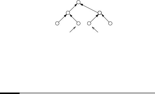

472 |
Ch. 11 Digital Signatures |
11.7.1 Arbitrated digital signatures
11.107 Definition An arbitrated digital signature scheme is a digital signature mechanism requiring an unconditionally trusted third party (TTP) as part of the signature generation and verification.
Algorithm 11.109 requires a symmetric-key encryption algorithm E = {Ek : k K} where K is the key space. Assume that the inputs and outputs of each Ek are l-bit strings, and let h: {0,1} −→ {0,1}l be a one-way hash function. The TTP selects a key kT K which it keeps secret. In order to verify a signature, an entity must share a symmetric key with the TTP.
11.108 Algorithm Key generation for arbitrated signatures
SUMMARY: each entity selects a key and transports it secretly with authenticity to the TTP. Each entity A should do the following:
1.Select a random secret key kA K.
2.Secretly and by some authentic means, make kA available to the TTP.
11.109 Algorithm Signature generation and verification for arbitrated signatures
SUMMARY: entity A generates signatures using EkA . Any entity B can verify A’s signature with the cooperation of the TTP.
1. Signature generation. To sign a message m, entity A should do the following:
(a) A computes H = h(m).
(b) A encrypts H with E to get u = EkA (H).
(c) A sends u along with some identification string IA to the TTP.
(d) The TTP computes E−1(u) to get H.
kA
(e) The TTP computes s = EkT (H||IA) and sends s to A.
(f) A’s signature for m is s.
2. Verification. Any entity B can verify A’s signature s on m by doing the following:
(a) B computes v = EkB (s).
(b) B sends v and some identification string IB to the TTP.
(c) The TTP computes E−1(v) to get s.
kB
(d) The TTP computes E−1(s) to get H IA.
kT
(e) The TTP computes w = EkB (H IA) and sends w to B.
(f) B computes E−1(w) to get H IA.
kB
B computes H
(h)B accepts the signature if and only if H = H.= h(m) from(g) m.
11.110 Note (security of arbitrated signature scheme) The security of Algorithm 11.109 is based on the symmetric-key encryption scheme chosen and the ability to distribute keys to participants in an authentic manner. §13.3 discusses techniques for distributing confidential keys.

§11.7 Other signature schemes |
473 |
11.111 Note (performance characteristics of arbitrated signatures) Since symmetric-key algorithms are typically much faster than public-key techniques, signature generation and verification by Algorithm 11.109 are (relatively) very efficient. A drawback is that interaction with the TTP is required, which places a much higher burden on the TTP and requires additional message exchanges between entities and the TTP.
11.7.2 ESIGN
ESIGN (an abbreviation for Efficient digital SIGNature) is another digital signature scheme whose security relies on the difficulty of factoring integers. It is a signature scheme with appendix and requires a one-way hash function h: {0,1} −→ Zn.
11.112 Algorithm Key generation for ESIGN
SUMMARY: each entity creates a public key and corresponding private key. Each entity A should do the following:
1.Select random primes p and q such that p ≥ q and p, q are roughly of the same bitlength.
2.Compute n = p2q.
3.Select a positive integer k ≥ 4.
4.A’s public key is (n,k); A’s private key is (p,q).
11.113 Algorithm ESIGN signature generation and verification
SUMMARY: the signing algorithm computes an integer s such that sk mod n lies in a certain interval determined by the message. Verification demonstrates that sk mod n does indeed lie in the specified interval.
1.Signature generation. To sign a message m which is a bitstring of arbitrary length, entity A should do the following:
(a)Compute v = h(m).
(b)Select a random secret integer x, 0 ≤ x < pq.
(c)Compute w = ((v − xk) mod n)/(pq) and y = w · (kxk−1)−1 mod p.
(d)Compute s = x + ypq mod n.
(e)A’s signature for m is s.
2.Verification. To verify A’s signature s on m, B should do the following:
(a)Obtain A’s authentic public key (n,k).
(b)Compute u = sk mod n and z = h(m).
(c)If z ≤ u ≤ z + 2 23 lg n , accept the signature; else reject it.
Proof that signature verification works. Note that s |
k |
|
|
|
k |
≡ |
|
|
k |
k |
k−i |
|
i |
||||||||||||||||||||
|
≡ (x+ypq) |
|
|
i=0 |
i |
x |
(ypq) |
||||||||||||||||||||||||||
≡ |
xk |
+ |
kypqxk−1 |
(mod |
n . But kxk−1y |
≡ |
w (mod p) and, thus, kxk−1y = w + lp for |
||||||||||||||||||||||||||
|
|
|
|
|
|
) |
|
|
|
|
|
|
|
|
|
|
|
|
|
|
|
|
|
|
|
||||||||
|
|
|
Z Hence, sk |
|
|
xk |
|
pq w |
|
lp |
|
|
xk |
|
|
pqw |
|
xk |
|
pq |
|
(h(m)−xk)modn |
|
||||||||||
|
|
|
|
|
|
|
|
|
|
|
|
|
|
|
|
|
|
≡ |
|||||||||||||||
some l . |
x |
k |
jn |
|
≡ |
|
|
+ |
( |
+ |
|
) ≡ |
|
+ |
|
≡ |
|
+ |
|
|
pq |
|
|||||||||||
xk + pq |
|
|
|
|
|
|
|
|
|
|
|
|
|
|
|
|
|
|
|
|
|
|
|
|
|
|
|
||||||
h(m)− |
+ |
+ |
(mod n), where = (xk − h(m)) mod pq. Therefore, sk ≡ |
||||||||||||||||||||||||||||||
pq |
|
|
|||||||||||||||||||||||||||||||
xk + h(m) − xk + ≡ h(m) + (mod n). Since 0 ≤ < pq, it follows that h(m) ≤ 23 lg n , as required.

474 Ch. 11 Digital Signatures
11.114 Example (ESIGN for artificially small parameters) In Algorithm 11.113, take messages to be integers m, 0 ≤ m < n, and the hash function h to be h(m) = m.
Key generation. A selects primes p = 17389 and q = 15401, k = 4, and computes n = p2q = 4656913120721. A’s public key is (n = 4656913120721,k = 4); A’s private key is (p = 17389,q = 15401).
Signature generation. To sign the message m = 3111527988477, A computes v = h(m)
= 3111527988477, and selects x = 14222 such that 0 ≤ x < pq. A then computes w = |
|||||
|
= ( |
) |
|
× |
|
((v − xk) mod n)/(pq) |
= 2848181921806/267807989 = 10635.16414 = 10636 |
||||
and y |
w kxk−1 |
−1 mod p = 10636(4 |
|
142223)−1 mod 17389 = 9567. Finally, A |
|
computes the signature s = x + ypq mod n = 2562119044985.
Signature verification. B obtains A’s public key (n = 4656913120721,k = 4), and computes u = sk mod n = 3111751837675. Since 3111527988477 ≤ 3111751837675 ≤ 3111527988477 + 229, B accepts the signature (here, 32 lg n = 29).
11.115 Note (security of ESIGN)
(i)The modulus n = p2q in Algorithm 11.113 differs from an RSA modulus by having a repeated factor of p. It is unknown whether or not moduli of this form are easier to factor than integers which are simply the product of two distinct primes.
(ii)Given a valid signature s for a message m, an adversary could forge a signature for
a message m if h(m ) is such that h(m ) ≤ u ≤ h(m ) + 2 23 lg n (where u = sk mod n). If an m with this property is found, then s will be a signature for it. This will occur if h(m) and h(m ) agree in the high-order (lg n)/3 bits. Assuming that h behaves like a random function, one would expect to try 2(lg n)/3 different values of m before observing this.
(iii)Another possible approach to forging is to find a pair of messages m and m such that h(m) and h(m ) agree in the high-order (lg n)/3 bits. By the birthday paradox (Fact 2.27(ii)), one can expect to find such a pair in O(2(lg n)/6) trials. If an adversary
is able to get the legitimate signer to sign m, the same signature will be a signature for m .
(iv)For the size of the integer n necessary to make the factorization of n infeasible, (ii) and (iii) above are extremely unlikely possibilities.
11.116 Note (performance characteristics of ESIGN signatures) Signature generation in Algorithm 11.113 is very efficient. For small values of k (e.g., k = 4), the most computationally intensive part is the modular inverse required in step 1c. Depending on the implementation, this corresponds to a small number of modular multiplications with modulus p. For k = 4 and a 768-bit modulus n, ESIGN signature generation may be between one and two orders of magnitude (10 to 100 times) faster than RSA signature generation with an equivalent modulus size. Signature verification is also very efficient and is comparable to RSA with a small public exponent.
11.8 Signatures with additional functionality
The mechanisms described in this section provide functionality beyond authentication and non-repudiation. In most instances, they combine a basic digital signature scheme (e.g., RSA) with a specific protocol to achieve additional features which the basic method does not provide.
§11.8 Signatures with additional functionality |
475 |
11.8.1 Blind signature schemes
Rather than signature schemes as described in §11.2, blind signature schemes are two-party protocols between a sender A and a signer B. The basic idea is the following. A sends a piece of information to B which B signs and returns to A. From this signature, A can compute B’s signature on an a priori message m of A’s choice. At the completion of the protocol, B knows neither the message m nor the signature associated with it.
The purpose of a blind signature is to prevent the signer B from observing the message it signs and the signature; hence, it is later unable to associate the signed message with the sender A.
11.117 Example (applications of blind signatures) Blind signature schemes have applications where the sender A (the customer) does not want the signer B (the bank) to be capable of associating a postiori a message m and a signature SB(m) to a specific instance of the protocol. This may be important in electronic cash applications where a message m might represent a monetary value which A can spend. When m and SB(m) are presented to B for payment, B is unable to deduce which party was originally given the signed value. This allows A to remain anonymous so that spending patterns cannot be monitored.
A blind signature protocol requires the following components:
1.A digital signature mechanism for signer B. SB(x) denotes the signature of B on x.
2.Functions f and g (known only to the sender) such that g(SB(f(m))) = SB(m). f is called a blinding function, g an unblinding function, and f(m) a blinded message.
Property 2 places many restrictions on the choice of SB and g.
11.118 Example (blinding function based on RSA) Let n = pq be the product of two large random primes. The signing algorithm SB for entity B is the RSA signature scheme (Algorithm 11.19) with public key (n,e) and private key d. Let k be some fixed integer with gcd(n,k) = 1. The blinding function f : Zn −→ Zn is defined by f(m) = m · ke mod n and the unblinding function g: Zn −→ Zn by g(m) = k−1m mod n. For this choice of f, g, and SB, g(SB(f(m))) = g(SB(mke mod n)) = g(mdk mod n) = md mod n =
SB(m), as required by property 2.
Protocol 11.119 presents a blind signature scheme which uses the digital signature mechanism and functions f and g described in Example 11.118.
11.119 Protocol Chaum’s blind signature protocol
SUMMARY: sender A receives a signature of B on a blinded message. From this, A computes B’s signature on a message m chosen a priori by A, 0 ≤ m ≤ n − 1. B has no knowledge of m nor the signature associated with m.
1.Notation. B’s RSA public and private keys are (n,e) and d, respectively. k is a random secret integer chosen by A satisfying 0 ≤ k ≤ n − 1 and gcd(n,k) = 1.
2.Protocol actions.
(a)(blinding) A computes m = mke mod n and sends this to B.
(b)(signing) B computes s = (m )d mod n which it sends to A.
(c)(unblinding) A computes s = k−1s mod n, which is B’s signature on m.

476 |
Ch. 11 Digital Signatures |
11.8.2 Undeniable signature schemes
Undeniable signature schemes are distinct from digital signatures in the sense of §11.2 in that the signature verification protocol requires the cooperation of the signer. The following example describes two scenarios where an undeniable signature could be applied.
11.120 Example (scenarios for undeniable signatures)
(i)Entity A (the customer) wishes to gain access to a secured area controlled by entity B (the bank). The secured area might, for example, be a safety-deposit box room. B requires A to sign a time and date document before access is granted. If A uses an undeniable signature, then B is unable to prove (at some later date) to anyone that A used the facility without A’s direct involvement in the signature verification process.
(ii)Suppose some large corporation A creates a software package. A signs the package and sells it to entity B, who decides to make copies of this package and resell it to a third party C. C is unable to verify the authenticity of the software without the cooperation of A. Of course, this scenario does not prevent B from re-signing the package
with its own signature but the marketing advantage associated with corporation A’s name is lost to B. It will also be easier to trace the fraudulent activity of B.
11.121 Algorithm Key generation for Algorithm 11.122
SUMMARY: each entity selects a private key and corresponding public key. Each entity A should do the following:
1.Select a random prime p = 2q + 1 where q is also a prime.
2.(Select a generator α for the subgroup of order q in Zp.)
2.1Select a random element β Zp and compute α = β(p−1)/q mod p.
2.2If α = 1 then go to step 2.1.
3.Select a random integer a {1,2,... ,q − 1} and compute y = αa mod p.
4.A’s public key is (p,α,y); A’s private key is a.
11.122 Algorithm Chaum-van Antwerpen undeniable signature scheme
SUMMARY: A signs a message m belonging to the subgroup of order q in Zp. Any entity
Bcan verify this signature with the cooperation of A.
1.Signature generation. Entity A should do the following:
(a)Compute s = ma mod p.
(b)A’s signature on message m is s.
2.Verification. The protocol for B to verify A’s signature s on m is the following:
(a)B obtains A’s authentic public key (p,α,y).
(b)B selects random secret integers x1,x2 {1,2,... ,q − 1}.
(c)B computes z = sx1 yx2 mod p and sends z to A.
(d)A computes w=(z)a−1 mod p (where aa−1 ≡ 1 (mod q)) and sends w to B.
(e)B computes w = mx1 αx2 mod p and accepts the signature if and only if w = w .

§11.8 Signatures with additional functionality |
477 |
Proof that signature verification works.
w ≡ (z)a−1 ≡ (sx1 yx2 )a−1 ≡ (max1 αax2 )a−1 ≡ mx1 αx2 ≡ w mod p,
as required.
Fact 11.123 states that, with high probability, an adversary is unable to cause B to accept a fraudulent signature.
11.123 Fact (detecting forgeries of undeniable signatures) Suppose that s is a forgery of A’s signature for a message m, i.e., s =ma mod p. Then the probability of B accepting the signature in Algorithm 11.122 is only 1/q; this probability is independent of the adversary’s computational resources.
11.124 Note (disavowing signatures) The signer A could attempt to disavow a (valid) signature constructed by Algorithm 11.122 in one of three ways:
(i)refuse to participate in the verification protocol of Algorithm 11.122;
(ii)perform the verification protocol incorrectly; or
(iii)claim a signature a forgery even though the verification protocol is successful.
Disavowing a signature by following (i) would be considered as an obvious attempt at (wrongful) repudiation. (ii) and (iii) are more difficult to guard against, and require a disavowal protocol (Protocol 11.125).
Protocol 11.125 essentially applies the verification protocol of Algorithm 11.122 twice and then performs a check to verify that A has performed the protocol correctly.
11.125 Protocol Disavowal protocol for Chaum-van Antwerpen undeniable signature scheme
SUMMARY: this protocol determines whether the signer Ais attempting to disavow a valid signature s using Algorithm 11.122, or whether the signature is a forgery.
1.B obtains A’s authentic public key (p,α,y).
2.B selects random secret integers x1,x2 {1,2,... ,q − 1}, and computes z = sx1 yx2 mod p, and sends z to A.
3.A computes w = (z)a−1 mod p (where aa−1 ≡ 1 (mod q)) and sends w to B.
4.If w = mx1 αx2 mod p, B accepts the signature s and the protocol halts.
5.B selects random secret integers x1,x2 {1,2,... ,q − 1}, and computes z = sx1 yx2 mod p, and sends z to A.
6.A computes w = (z )a−1 mod p and sends w to B.
7.If w = mx1 αx2 mod p, B accepts the signature s and the protocol halts.
8.B computes c = (wα−x2 )x1 mod p and c = (w α−x2 )x1 mod p. If c = c , then B concludes that s is a forgery; otherwise, B concludes that the signature is valid and A is attempting to disavow the signature s.
Fact 11.126 states that Protocol 11.125 achieves its desired objectives.
11.126 Fact Let m be a message and suppose that s is A’s (purported) signature on m.
(i)If sis a forgery, i.e., s =ma mod p, and if Aand B follow Protocol 11.125 correctly, then w = w (and hence, B’s conclusion that s is a forgery is correct).
(ii)Suppose that s is indeed A’s signature for m, i.e., s = ma mod p. Suppose that
B follows Protocol 11.125 correctly, but that A does not. Then the probability that w = w (and hence A succeeds in disavowing the signature) is only 1/q.

478 |
Ch. 11 Digital Signatures |
11.127 Note (security of undeniable signatures)
(i)The security of Algorithm 11.122 is dependent on the intractability of the discrete logarithm problem in the cyclic subgroup of order q in Zp (see §3.6.6).
(ii)Suppose verifier B records the messages exchanged in step 2 of Algorithm 11.122, and also the random values x1, x2 used in the protocol. A third party C should never accept this transcript from B as a verification of signature s. To see why this is the case, it suffices to show how B could contrive a successful transcript of step 2 of Al-
gorithm 11.122 without the signer A’s participation. B chooses a message m, inte- gers x1, x2 and l in the interval [1,q−1], and computes s = ((mx1 αx2 )l−1 y−x2 )x−1 1 mod p. The protocol message from B to A would be z = sx1 yx2 mod p, and from A to B would be w = zl mod p. Algorithm 11.122 will accept s as a valid signature of A for message m. This argument demonstrates that signatures can only be verified
by interacting directly with the signer.
11.8.3Fail-stop signature schemes
Fail-stop digital signatures are digital signatures which permit an entity A to prove that a signature purportedly (but not actually) signed by A is a forgery. This is done by showing that the underlying assumption on which the signature mechanism is based has been compromised. The ability to prove a forgery does not rely on any cryptographic assumption, but may fail with some small probability; this failure probability is independent of the computing power of the forger. Fail-stop signature schemes have the advantage that even if a very powerful adversary can forge a single signature, the forgery can be detected and the signing mechanism no longer used. Hence, the term fail-then-stop is also appropriate. A fail-stop signature scheme should have the following properties:
1.If a signer signs a message according to the mechanism, then a verifier upon checking the signature should accept it.
2.A forger cannot construct signatures that pass the verification algorithm without doing an exponential amount of work.
3.If a forger succeeds in constructing a signature which passes the verification test then, with high probability, the true signer can produce a proof of forgery.
4.A signer cannot construct signatures which are at some later time claimed to be forgeries.
Algorithm 11.130 is an example of a fail-stop mechanism. As described, it is a one-time signature scheme, but there are ways to generalize it to allow multiple signings; using authentication trees is one possibility (see §11.6.3). The proof-of-forgery algorithm is presented in Algorithm 11.134.
11.128 Algorithm Key generation for Algorithm 11.130
SUMMARY: key generation is divided between entity A and a trusted third party (TTP).
1.The TTP should do the following:
(a)Select primes p and q such that q divides (p − 1) and the discrete logarithm problem in Zq is intractable.
(b)(Select a generator α for the cyclic subgroup G of Zp having order q.)
(i)Select a random element g Zp and compute α = g(p−1)/q mod p.
(ii)If α = 1 then go to step (i).

§11.8 Signatures with additional functionality |
479 |
(c)Select a random integer a, 1 ≤ a ≤ q − 1, and compute β = αa mod p. The integer a is kept secret by the TTP.
(d)Send (p,q,α,β) in the clear to entity A.
2.Entity A should do the following:
(a)Select random secret integers x1,x2,y1,y2 in the interval [0,q − 1].
(b)Compute β1 = αx1 βx2 and β2 = αy1 βy2 mod p.
(c) A’s public key is (β1,β2,p,q,α,β); A’s private key is the quadruple x = (x1,x2,y1,y2).
11.129 Note (TTP’s secret information) Assuming that the discrete logarithm problem in the subgroup of order q in Zp is intractable in Algorithm 11.128, the only entity which knows a, the discrete logarithm of β to the base α, is the TTP.
11.130 Algorithm Fail-stop signature scheme (van Heijst-Pedersen)
SUMMARY: this is a one-time digital signature scheme whose security is based on the discrete logarithm problem in the subgroup of order q in Zp.
1.Signature generation. To sign a message m [0,q −1], A should do the following:
(a)Compute s1,m = x1 + my1 mod q and s2,m = x2 + my2 mod q.
(b)A’s signature for m is (s1,m,s2,m).
2.Verification. To verify A’s signature (s1,m,s2,m) on m, B should do the following:
(a)Obtain A’s authentic public key (β1,β2,p,q,α,β).
(b)Compute v1 = β1β2m mod p and v2 = αs1,m βs2,m mod p.
(c)Accept the signature if and only if v1 = v2.
Proof that signature verification works.
v1 ≡ |
β1 |
βm ≡ (αx1 |
βx2 )(αy1 βy2 )m ≡ αx1+my1 |
βx2+my2 |
|
|
2 |
|
|
≡ |
αs1,m βs2,m ≡ v2 (mod p). |
|
||
Algorithm 11.130 is a one-time signature scheme since A’s private key x can be computed if two messages are signed using x. Before describing the algorithm for proof of forgery (Algorithm 11.134), a number of facts are needed. These are given in Fact 11.131 and illustrated in Example 11.132.
11.131 Fact (number of distinct quadruples representing a public key and a signature) Suppose that A’s public key in Algorithm 11.130 is (β1,β2,p,q,α,β) and private key is the quadruple x = (x1,x2,y1,y2).
(i)There are exactly q2 quadruples x = (x1,x2,y1,y2) with x1,x2,y1,y2 Zq which yield the same portion (β1,β2) of the public key.
(ii)Let T be the set of q2 quadruples which yield the same portion of the public key (β1,β2). For each m Zq, there are exactly q quadruples in T which give the same
signature (s1,m,s2,m) for m (where a signature is as described in Algorithm 11.130). Hence, the q2 quadruples in T give exactly q different signatures for m.
(iii)Let m Zq be a message different from m. Then the q quadruples in T which yield A’s signature (s1,m,s2,m) for m, yield q different signatures for m .

480 Ch. 11 Digital Signatures
11.132 Example (illustration of Fact 11.131) Let p = 29 and q = 7. α = 16 is a generator of the subgroup of order q in Zp. Take β = α5 mod 29 = 23. Suppose A’s private key is
|
= (2,3,5,2); A’s public key is β1 = α2β3 mod 29 = 7, β2 |
= α5β2 mod 29 = 16. |
||||||||
x |
||||||||||
The following table lists the q2 = 49 quadruples which give the same public key. |
||||||||||
|
|
|
|
|
|
|
|
|
|
|
|
1603 |
2303 |
3003 |
4403 |
5103 |
6503 |
|
0203 |
|
|
|
1610 |
2310 |
3010 |
4410 |
5110 |
6510 |
|
0210 |
|
|
|
1624 |
2324 |
3024 |
4424 |
5124 |
6524 |
|
0224 |
|
|
|
1631 |
2331 |
3031 |
4431 |
5131 |
6531 |
|
0231 |
|
|
|
1645 |
2345 |
3045 |
4445 |
5145 |
6545 |
|
0245 |
|
|
|
1652 |
2352 |
3052 |
4452 |
5152 |
6552 |
|
0252 |
|
|
|
1666 |
2366 |
3066 |
4466 |
5166 |
6566 |
|
0266 |
|
|
If the 49 quadruples of this table are used to sign the message m = 1, exactly q = 7 signature pairs (s1,m,s2,m) arise. The next table lists the possibilities and those quadruples which generate each signature.
signature pair |
|
(2,6) |
(3,3) |
(4,0) |
(5,4) |
(6,1) |
(0,5) |
(1,2) |
|
|
|
|
|
|
|
|
|
quadruples |
|
1610 |
1624 |
1631 |
1645 |
1652 |
1666 |
1603 |
|
|
2303 |
2310 |
2324 |
2331 |
2345 |
2352 |
2366 |
|
|
3066 |
3003 |
3010 |
3024 |
3031 |
3045 |
3052 |
|
|
4452 |
4466 |
4403 |
4410 |
4424 |
4431 |
4445 |
|
|
5145 |
5152 |
5166 |
5103 |
5110 |
5124 |
5131 |
|
|
6531 |
6545 |
6552 |
6566 |
6503 |
6510 |
6524 |
|
|
0224 |
0231 |
0245 |
0252 |
0266 |
0203 |
0210 |
|
|
|
|
|
|
|
|
|
The next table lists, for each message m Z7, all signature pairs for the 7 quadruples which yield A’s signature (0,5) for m = 1.
|
|
|
|
|
m |
|
|
|
quadruple |
|
0 |
1 |
2 |
3 |
4 |
5 |
6 |
|
|
|
|
|
|
|
|
|
1666 |
|
16 |
05 |
64 |
53 |
42 |
31 |
20 |
2352 |
|
23 |
05 |
50 |
32 |
14 |
66 |
41 |
3045 |
|
30 |
05 |
43 |
11 |
56 |
24 |
62 |
4431 |
|
44 |
05 |
36 |
60 |
21 |
52 |
13 |
5124 |
|
51 |
05 |
22 |
46 |
63 |
10 |
34 |
6510 |
|
65 |
05 |
15 |
25 |
35 |
45 |
55 |
0203 |
|
02 |
05 |
01 |
04 |
00 |
03 |
06 |
|
|
|
|
|
|
|
|
|
11.133 Note (probability of successful forgery in Algorithm 11.130) Suppose that an adversary (the forger) wishes to derive A’s signature on some message m . There are two possibilities to consider.
(i)The forger has access only to the signer’s public key (i.e., the forger is not in pos-
session of a message and valid signature). By Fact 11.131(ii), the probability that the signature created by the adversary is the same as A’s signature for m is only q/q2 = 1/q; this probability is independent of the adversary’s computational resources.
(ii)The forger has access to a message m and a signature (s1,m,s2,m) created by the signer. By Fact 11.131(iii), the probability that the signature created by the adversary is the same as A’s signature for m is only 1/q; again, this probability is independent
of the adversary’s computational resources.

§11.9 Notes and further references |
481 |
Suppose now that an adversary has forged A’s signature on a message, and the signature passed the verification stage in Algorithm 11.130. The objective is that A should be able to prove that this signature is a forgery. The following algorithm shows how A can, with high probability, use the forged signature to derive the secret a. Since a was supposed to have been known only to the TTP (Note 11.129), it serves as proof of forgery.
11.134 Algorithm Proof-of-forgery algorithm for Algorithm 11.130
SUMMARY: to prove that a signature s = (s1,m,s2,m) on a message m is a forgery, the signer derives the integer a = logα β which serves as proof of forgery.
The signer (entity A) should do the following:
1.Compute a signature pair s = (s1,m,s2,m) for message m using its private key x (see Algorithm 11.128).
2.If s = s return to step 1.
3.Compute a = (s1,m − s1,m) · (s2,m − s2,m)−1 mod q.
Proof that Algorithm 11.134 works. By Fact 11.131(iii), the probability that s = s in
step 1 of Algorithm 11.134 is 1/q. From the verification algorithm (Algorithm 11.130),
αs1,m βs2,m ≡ αs1,m βs2,m (mod p) or αs1,m−s1,m ≡ αa(s2,m−s2,m) (mod p) or s1,m −
s1,m ≡ a(s2,m − s2,m) (mod q). Hence, a = (s1,m − s1,m) · (s2,m − s2,m)−1 mod q.
11.135 Remark (disavowing signatures) In order for a signer to disavow a signature that it created with Algorithm 11.134, an efficient method for computing logarithms is required.
11.9 Notes and further references
§11.1
The concept of a digital signature was introduced in 1976 by Diffie and Hellman [344, 345]. Although the idea of a digital signature was clearly articulated, no practical realization emerged until the 1978 paper by Rivest, Shamir, and Adleman [1060]. Digital signatures appear to have been independently discovered by Merkle [849, 850] but not published until 1978. One of Merkle’s contributions is discussed in §11.6.2. Other early research was due to Lamport [738], Rabin [1022, 1023], and Matyas [801].
A detailed survey on digital signatures is given by Mitchell, Piper, and Wild [882]. A thorough discussion of a selected subset of topics in the area is provided by Stinson [1178]. Other sources which provide a good overview are Meyer and Matyas [859], Goldwasser, Micali, and Rivest [484], Rivest [1054], and Schneier [1094].
§11.2
The original proposal for a digital signature scheme by Diffie and Hellman [344] considered only digital signatures with message recovery. The first discussion of digital signature schemes with appendix (although the term was not used per se) appears to be in the patent by Merkle and Hellman [553]. Davies and Price [308] and Denning [326] give brief introductions to digital signatures but restrict the discussion to digital signature schemes with message recovery and one-time digital signature schemes. Mitchell, Piper, and Wild [882] and Stinson [1178] give abstract definitions of digital signature schemes somewhat less general than those given in §11.2.

482 |
Ch. 11 Digital Signatures |
Excellent discussions on attacks against signature schemes are provided by Goldwasser, Micali, and Rivest [484] and Rivest [1054]. The former refers to the discovery of a functionally equivalent signing algorithm as universal forgery, and separates chosen-message attacks into generic chosen-message attacks and directed chosen-message attacks.
Many proposed digital signature schemes have been shown to be insecure. Among the most prominent of these are the Merkle-Hellman knapsack scheme proposed by Merkle and Hellman [857], shown to be totally breakable by Shamir [1114]; the Shamir fast signature scheme [1109], shown to be totally breakable by Odlyzko [939]; and the Ong-Schnorr-Shamir (OSS) scheme [958], shown to be totally breakable by Pollard (see Pollard and Schnorr [988]). Naccache [914] proposed a modification of the Ong-Schnorr-Shamir scheme to avoid the earlier attacks.
§11.3
The RSA signature scheme (Algorithm 11.19), discovered by Rivest, Shamir, and Adleman [1060], was the first practical signature scheme based on public-key techniques.
The multiplicative property of RSA (§11.3.2(ii)) was first exploited by Davida [302]. Denning [327] reports and expands on Davida’s attack and credits Moore with a simplification. Gordon [515] uses the multiplicative property of RSA to show how to create public-key parameters and associated (forged) certificates if the signing authority does not take adequate precautions. The existential attack on RSA signatures having certain types of redundancy (Example 11.21) is due to de Jonge and Chaum [313]. Evertse and van Heijst [381] consider other types of attacks on RSA signatures which also rely on the multiplicative property.
The reblocking problem (§11.3.3(i)) is discussed by Davies and Price [308], who attribute the method of prescribing the form of the modulus to Guillou. An alternate way of constructing an (even) t-bit modulus n = pq having a 1 in the high-order position followed by k 0’s is the following. Construct an integer u = 2t + w2t/2 for some randomly selected (t/2 − k)-bit integer w. Select a (t/2)-bit prime p, and divide p into u to get a quotient q and a remainder r (i.e., u = pq + r). If q is a prime number, then n = pq is an RSA modulus of the required type. For example, if t = 14 and k = 3, let u = 214 + w27 where w = 11. If p = 89, then q = 199 and n = pq = 17711. The binary representation of n is
100010100101111.
The Rabin public-key signature scheme (Algorithm 11.25) is due to Rabin [1023]. Verification of signatures using the Rabin scheme is efficient since only one modular multiplication is required (cf. Note 11.33). Beller and Yacobi [101] take advantage of this aspect in their authenticated key transport protocol (see §12.5.3).
The modified-Rabin signature scheme (Algorithm 11.30) is derived from the RSA variant proposed by Williams [1246] (see also page 315). The purpose of the modification is to provide a deterministic procedure for signing. A similar methodology is incorporated in ISO/IEC 9796 (§11.3.5). The modified scheme can be generalized to other even public exponents besides e = 2. If gcd(e,(p − 1)(q − 1)/4) = 1, then exponentiation by e is a permutation of Qn.
ISO/IEC 9796 [596] became an international standard in October of 1991. This standard provides examples based on both the RSA and Rabin digital signature mechanisms. Although the standard permits the use of any digital signature scheme with message recovery which provides a t-bit signature for a 2t -bit message, the design was specifically tailored for the RSA and Rabin mechanisms. For design motivation, see Guillou et al. [525]. At the time of publication of ISO/IEC 9796, no other digital signature schemes providing message recovery were known, but since then several have been found; see Koyama et al. [708].
§11.9 Notes and further references |
483 |
ISO/IEC 9796 is effective for signing messages which do not exceed a length determined by the signature process. Quisquater [1015] proposed a method for extending the utility of ISO/IEC 9796 to longer messages. Briefly, the modified scheme is as follows. Select a oneway hash function h which maps bitstrings of arbitrary length to k-bitstrings. If the signing capability of ISO/IEC 9796 is t bits and m is an n-bit message where n > t, then m is partitioned into two bitstrings mc and ms, where mc is (n−t+ k) bits long. Compute d = h(m) and form m = ms d; m is a string of bitlength t. Sign m using ISO/IEC 9796 to get J. The signature on message m is mc J. This provides a randomized digital signature mechanism with message recovery, where the hash function provides the randomization.
§11.3.6 is from PKCS #1 [1072]. This document describes formatting for both encryption and digital signatures but only those details pertinent to digital signatures are mentioned here. The specification does not include message recovery as ISO/IEC 9796 does. It also does not specify the size of the primes, how they should be generated, nor the size of public and private keys. It is suggested that e = 3 or e = 216 + 1 are widely used. The only attacks mentioned in PKCS #1 (which the formatting attempts to prevent) are those by den Boer and Bosselaers [324], and Desmedt and Odlyzko [341].
§11.4
The Feige-Fiat-Shamir digital signature scheme (Algorithm 11.40), proposed by Feige, Fiat, and Shamir [383], is a minor improvement of the Fiat-Shamir signature scheme [395], requiring less computation and providing a smaller signature. Fiat and Shamir [395] prove that their scheme is secure against existential forgery provided that factoring is intractable and that h is a truly random function. Feige, Fiat, and Shamir [383] prove that their modification has the same property.
Note 11.44 was suggested by Fiat and Shamir [395]. Note 11.45 is due to Micali and Shamir [868], who suggest that only the modulus nA of entity A needs to be public if v1,v2,... ,vk are system-wide parameters. Since all entities have distinct moduli, it is unlikely that vj Qn, 1 ≤ j ≤ k, for many different values of n. To overcome this problem, Micali and Shamir claim that some perturbation of k public values is possible to ensure that the resulting values are quadratic residues with respect to a particular modulus, but do not specify any method which provides the necessary perturbation.
The GQ signature scheme (Algorithm 11.48) is due to Guillou and Quisquater [524].
§11.5
The DSA (Algorithm 11.56) is due to Kravitz [711] and was proposed as a Federal Information Processing Standard in August of 1991 by the U.S. National Institute for Science and Technology. It became the Digital Signature Standard (DSS) in May 1994, as specified in FIPS 186 [406]. Smid and Branstad [1157] comment that the DSA was selected based on a number of important factors: the level of security provided, the applicability of patents, the ease of export from the U.S., the impact on national security and law enforcement, and the efficiency in a number of government and commercial applications. They provide a comparison of the computational efficiencies of DSA and RSA and address a number of negative responses received during the FIPS public comment period.
Naccache et al. [916] describe a number of techniques for improving the efficiency of the DSA. For example, the computation of k−1 mod q in step 1c of Algorithm 11.56 can be replaced by the random generation of an integer b, the computation of u = bk mod q and s = b · {h(m) + ar} mod q. The signature is (r,s,u). The verifier computes u−1 mod q and u−1s mod q = s. Verification of the signature (r,s) now proceeds as in Algorithm 11.56. This variant might be useful for signature generation in chipcard applications where computing power is limited. Naccache et al. also propose the idea of use and throw coupons
484 |
Ch. 11 Digital Signatures |
which eliminate the need to compute r = (αk mod p) mod q. Since this exponentiation is the most computationally intensive portion of DSA signature generation, use and throw coupons greatly improve efficiency. Coupons require storage, and only one signature can be created for each coupon. If storage is limited (as is often the case), only a fixed number of DSA signatures can be created with this method.
B´eguin and Quisquater [82] show how to use an insecure server to aid in computations associated with DSA signature generation and verification. The method accelerates the computation of modular multiplication and exponentiation by using an untrusted auxiliary device to provide the majority of the computing. As such, it also applies to schemes other than DSA. Arazi [54] shows how to integrate a Diffie-Hellman key exchange into the DSA.
The ElGamal digital signature scheme (Algorithm 11.64) was proposed in 1984 by ElGamal [368]. ElGamal [368], Mitchell, Piper, and Wild [882], and Stinson [1178] comment further on its security.
Note 11.66(iv) is due to Bleichenbacher [153], as is Note 11.67(iii), which is a special case of the following more general result. Suppose p is a prime, α is a generator of Zp, and y is the public key of entity A for an instance of the ElGamal signature scheme. Suppose p − 1 = bq and logarithms in the subgroup of order b in Zp can be efficiently computed. Finally, suppose that a generator β = cq for some c,0 < c < b, and an integer t are known such that βt ≡ α (mod p). For message m, the pair (r,s) with r = β and s = t·{h(m) − cqz} mod (p−1) where z satisfies αqz ≡ yq (mod p) is a signature for message m which will be accepted by Algorithm 11.64. Bleichenbacher also describes how a trapdoor could be constructed for the ElGamal signature scheme when system-wide parameters p and α are selected by a fraudulent trusted third party.
Variations of the ElGamal signing equation described in §11.5.2 were proposed by ElGamal [366], Agnew, Mullin, and Vanstone [19], Kravitz [711], Schnorr [1098], and Yen and Laih [1259]. Nyberg and Rueppel [938] and, independently, Horster and Petersen [564], placed these variations in a much more general framework and compared their various properties.
ElGamal signatures based on elliptic curves over finite fields were first proposed by Koblitz [695] and independently by Miller [878] in 1985. A variation of the DSA based on elliptic curves and referred to as the ECDSA is currently being drafted for an IEEE standard.
The Schnorr signature scheme (Algorithm 11.78), due to Schnorr [1098], is derived from an identification protocol given in the same paper (see §10.4.4). Schnorr proposed a preprocessing method to improve the efficiency of the signature generation in Algorithm 11.78. Instead of generating a random integer k and computing αk mod p for each signature, a small number of integers ki and αki mod p, 1 ≤ i ≤ t, are precomputed and stored, and subsequently combined and refreshed for each signature. De Rooij [315] showed that this preprocessing is insecure if t is small.
Brickell and McCurley [207] proposed a variant of the Schnorr scheme. Their method uses a prime p such that p−1 is hard to factor, a prime divisor q of p−1, and an element αof order q in Zp. The signing equation is s = ae+k mod (p − 1) as opposed to the Schnorr equation s = ae+k mod q. While computationally less efficient than Schnorr’s, this variant has the advantage that its security is based on the difficulty of two hard problems: (i) computing logarithms in the cyclic subgroup of order q in Zp; and (ii) factoring p−1. If either of these problems is hard, then the problem of computing logarithms in Zp is also hard.
Okamoto [949] describes a variant of the Schnorr scheme which he proves to be secure, provided that the discrete logarithm problem in Zp is intractable and that correlation-free hash functions exist (no instance of a correlation-free hash function is yet known). Signa-
§11.9 Notes and further references |
485 |
ture generation and verification are not significantly more computationally intensive than in the Schnorr scheme; however, the public key is larger.
The Nyberg-Rueppel scheme (Algorithm 11.81) is due to Nyberg and Rueppel [936]. For an extensive treatment including variants, see Nyberg and Rueppel [938]. They note that unlike RSA, this signature scheme cannot be used for encryption since the signing transformation S has a left inverse, namely, the verification transformation V , but S is not the left inverse of V ; in other words, V (S(m)) = m for all m Zp, but S(V (m)) =m for most m Zp. The second paper also defines the notion of strong equivalence between signature schemes (two signature schemes are called strongly equivalent if the signature on a message m in one scheme can be transformed into the corresponding signature in the other scheme, without knowledge of the private key), and discusses how to modify DSA to provide message recovery.
Some digital signature schemes make it easy to conceal information in the signature which can only be recovered by entities privy to the concealment method. Information communicated this way is said to be subliminal and the conveying mechanism is called a subliminal channel. Among the papers on this subject are those of Simmons [1139, 1140, 1147, 1149]. Simmons [1139] shows that if a signature requires l1 bits to convey and provides l2 bits of security, then l1 −l2 bits are available for the subliminal channel. This does not imply that all l1 −l2 bits can, in fact, be used by the channel; this depends on the signature mechanism. If a large proportion of these bits are available, the subliminal channel is said to be broadband; otherwise, it is narrowband. Simmons [1149] points out that ElGamal-like signature schemes provide a broadband subliminal channel. For example, if the signing equation is s = k−1 · {h(m) − ar} mod (p − 1) where a is the private key known to both the signer and the recipient of the signature, then k can be used to carry the subliminal message. This has the disadvantage that the signer must provide the recipient with the private key, allowing the recipient to sign messages that will be accepted as having originated with the signer. Simmons [1147] describes narrowband channels for the DSA.
§11.6
Rabin [1022] proposed the first one-time signature scheme (Algorithm 11.86) in 1978. Lamport [738] proposed a similar mechanism, popularized by Diffie and Hellman [347], which does not require interaction with the signer for verification. Diffie suggested the use of a one-way hash function to improve the efficiency of the method. For this reason, the mechanism is often referred to as the Diffie-Lamport scheme. Lamport [738] also describes a more efficient method for one-time digital signatures, which was rediscovered by Bos and Chaum [172]. Bos and Chaum provide more substantial modifications which lead to a scheme that can be proven to be existentially unforgeable under adaptive chosen-message attack, provided RSA is secure.
Merkle’s one-time signature scheme (Algorithm 11.92) is due to Merkle [853]; see also §15.2.3(vi). The modification described in Note 11.95 is attributed by Merkle [853] to Winternitz. Bleichenbacher and Maurer [155] generalize the methods of Lamport, Merkle, and Winternitz through directed acyclic graphs and one-way functions.
Authentication trees were introduced by Merkle [850, 852, 853] at the time when publickey cryptography was in its infancy. Since public-key cryptography and, in particular, digital signatures had not yet been carefully scrutinized, it seemed prudent to devise alternate methods for providing authentication over insecure channels. Merkle [853] suggests that authentication trees provide as much versatility as public-key techniques and can be quite practical. An authentication tree, constructed by a single user to authenticate a large number of public values, requires the user to either regenerate the authentication path values
486 |
Ch. 11 Digital Signatures |
at the time of use or to store all authentication paths and values in advance. Merkle [853] describes a method to minimize the storage requirements if public values are used in a prescribed order.
The GMR scheme (Algorithm 11.102) is due to Goldwasser, Micali, and Rivest [484], who introduced the notion of a claw-free pair of permutations, and described the construction of a claw-free pair of permutations (Example 11.99) based on the integer factorization problem. Combining the one-time signature scheme with tree authentication gives a digital signature mechanism which Goldwasser, Micali and Rivest prove existentially unforgeable under an adaptive chosen-message attack. In order to make their scheme more practical, the tree authentication structure is constructed in such a way that the system must retain some information about preceding signatures (i.e., memory history is required). Goldreich [465] suggested modifications to both the general scheme and the example based on integer factorization (Example 11.99), removing the memory constraint and, in the latter, improving the efficiency of the signing procedure. Bellare and Micali [92] generalized the GMR scheme by replacing the claw-free pair of permutations by any trapdoor one-way permutation (the latter requiring a weaker cryptographic assumption). Naor and Yung [920] further generalized the scheme by requiring only the existence of a one-way permutation. The most general result is due to Rompel [1068], who proved that digital signature schemes which are secure against an adaptive chosen-message attack exist if and only if one-way functions exist. Although attractive in theory (due to the fact that secure digital signatures can be reduced to the study of a single structure), none of these methods seem to provide techniques as efficient as RSA and other methods which, although their security has yet to be proven rigorously, have withstood all attacks to date.
On-line/off-line digital signatures (see also §15.2.3(ix)) were introduced by Even, Goldreich, and Micali [377, 378] as a means to speed up the signing process in applications where computing resources are limited and time to sign is critical (e.g., chipcard applications). The method uses both one-time digital signatures and digital signatures arising from public-key techniques (e.g., RSA, Rabin, DSA). The off-line portion of the signature generation is to create a set of validation parameters for a one-time signature scheme such as the Merkle scheme (Algorithm 11.92), and to hash this set and sign the resulting hash value using a publickey signature scheme. Since the public-key signature scheme is computationally more intensive, it is done off-line. The off-line computations are independent of the message to be signed. The on-line portion is to sign the message using the one-time signature scheme and the validation parameters which were constructed off-line; this part of the signature process is very efficient. Signatures are much longer than would be the case if only the public-key signature mechanism were used to sign the message directly and, consequently, bandwidth requirements are a disadvantage of this procedure.
§11.7
The arbitrated digital signature scheme of Algorithm 11.109 is from Davies and Price [308], based on work by Needham and Schroeder [923].
ESIGN (Algorithm 11.113; see also §15.2.2(i)), proposed by Okamoto and Shiraishi [953], was motivated by the signature mechanism OSS devised earlier by Ong, Schnorr, and Shamir [958]. The OSS scheme was shown to be insecure by Pollard in a private communication. Ong, Schnorr, and Shamir [958] modified their original scheme but this too was shown insecure by Estes et al. [374]. ESIGN bases its security on the integer factorization problem and the problem of solving polynomial inequalities. The original version [953] proposed k = 2 as the appropriate value for the public key. Brickell and DeLaurentis [202] demonstrated that this choice was insecure. Their attack also extends to the case k = 3; see Brickell and Odlyzko [209, p.516]. Okamoto [948] revised the method by requiring
§11.9 Notes and further references |
487 |
k ≥ 4. No weaknesses for these values of k have been reported in the literature. Fujioka, Okamoto, and Miyaguchi [428] describe an implementation of ESIGN which suggests that it is twenty times faster than RSA signatures with comparable key and signature lengths.
§11.8
Blind signatures (§11.8.1) were introduced by Chaum [242], who described the concept, desired properties, and a protocol for untraceable payments. The first concrete realization of the protocol (Protocol 11.119) was by Chaum [243]. Chaum and Pedersen [251] provide a digital signature scheme which is a variant of the ElGamal signature mechanism (§11.5.2), using a signing equation similar to the Schnorr scheme (§11.5.3), but computationally more intensive for both signing and verification. This signature technique is then used to provide a blind signature scheme.
The concept of a blind signature was extended by Chaum [245] to blinding for unanticipated signatures. Camenisch, Piveteau, and Stadler [228] describe a blind signature protocol based on the DSA (Algorithm 11.56) and one based on the Nyberg-Rueppel scheme (Algorithm 11.81). Horster, Petersen, and Michels [563] consider a number of variants of these protocols. Stadler, Piveteau, and Camenisch [1166] extend the idea of a blind signature to a fair blind signature where the signer in cooperation with a trusted third party can link the message and signature, and trace the sender.
Chaum, Fiat, and Naor [250] propose a scheme for untraceable electronic cash, which allows a participant A to receive an electronic cash token from a bank. A can subsequently spend the token at a shop B, which need not be on-line with the bank to accept and verify the authenticity of the token. When the token is cashed at the bank by B, the bank is unable to associate it with A. If, however, A attempts to spend the token twice (double-spending), A’s identity is revealed. Okamoto [951] proposes a divisible electronic cash scheme. A divisible electronic coin is an element which has some monetary value associated with it, and which can be used to make electronic purchases many times, provided the total value of all transactions does not exceed the value of the coin.
Undeniable signatures (§11.8.2) were first introduced by Chaum and van Antwerpen [252], along with a disavowal protocol (Protocol 11.125). Chaum [246] shows how to modify the verification protocol for undeniable signatures (step 2 of Algorithm 11.122) to obtain a zero-knowledge verification.
One shortcoming of undeniable signature schemes is the possibility that the signer is unavailable or refuses to co-operate so that the signature cannot be verified by a recipient. Chaum [247] proposed the idea of a designated confirmer signature where the signer designates some entity as a confirmer of its signature. If the signer is unavailable or refuses to co-operate, the confirmer has the ability to interact with a recipient of a signature in order to verify it. The confirmer is unable to create signatures for the signer. Chaum [247] describes an example of designated confirmer signatures based on RSA encryption. Okamoto [950] provides a more indepth analysis of this technique and gives other realizations.
A convertible undeniable digital signature, introduced by Boyar et al. [181], is an undeniable signature (§11.8.2) with the property that the signer A can reveal a secret piece of information, causing all undeniable signatures signed by A to become ordinary digital signatures. These ordinary digital signatures can be verified by anyone using only the public key of A and requiring no interaction with A in the verification process; i.e., the signatures become self-authenticating. This secret information which is made available should not permit anyone to create new signatures which will be accepted as originating from A. As an application of this type of signature, consider the following scenario. Entity A signs all documents during her lifetime with convertible undeniable signatures. The secret piece of
488 |
Ch. 11 Digital Signatures |
information needed to convert these signatures to self-authenticating signatures is placed in trust with her lawyer B. After the death of A, the lawyer can make the secret information public knowledge and all signatures can be verified. B does not have the ability to alter or create new signatures on behalf of A. Boyar et al. [181] give a realization of the concept of convertible undeniable signatures using ElGamal signatures (§11.5.2) and describe how one can reveal information selectively to convert some, but not all, previously created signatures to self-authenticating ones.
Chaum, van Heijst, and Pfitzmann [254] provide a method for constructing undeniable signatures which are unconditionally secure for the signer.
Fail-stop signatures were introduced by Waidner and Pfitzmann [1227] and formally defined by Pfitzmann and Waidner [971]. The first constructions for fail-stop signatures used claw-free pairs of permutations (Definition 11.98) and one-time signature methods (see Pfitzmann and Waidner [972]). More efficient techniques were provided by van Heijst and Pedersen [1201], whose construction is the basis for Algorithm 11.130; they describe three methods for extending the one-time nature of the scheme to multiple signings. Van Heijst, Pedersen, and Pfitzmann [1202] extended the idea of van Heijst and Pedersen to fail-stop signatures based on the integer factorization problem.
Damg˚ard [298] proposed a signature scheme in which the signer can gradually and verifiably release the signature to a verifier.
Chaum and van Heijst [253] introduced the concept of a group signature. A group signature has the following properties: (i) only members of a predefined group can sign messages; (ii) anyone can verify the validity of a signature but no one is able to identify which member of the group signed; and (iii) in case of disputes, the signature can be opened (with or without the help of group members) to reveal the identity of the group member who signed it. Chen and Pedersen [255] extended this idea to provide group signatures with additional functionality.


490 |
Ch. 12 Key Establishment Protocols |
objectives. §12.3 and §12.4 discuss key transport and agreement protocols, respectively, based on symmetric techniques; the former includes several protocols involving an on-line trusted third party. §12.5 and §12.6 discuss key transport and agreement protocols, respectively, based on asymmetric techniques; the former includes protocols based on public-key encryption, some of which also employ digital signatures, while the latter includes selected variations of Diffie-Hellman key agreement. §12.7 and §12.8 consider secret sharing and conference keying, respectively. §12.9 addresses the analysis of key establishment protocols and standard attacks which must be countered. §12.10 contains chapter notes with references.
The particular protocols discussed provide a representative subset of the large number of practical key establishment protocols proposed to date, selected according to a number of criteria including historical significance, distinguishing merits, and practical utility, with particular emphasis on the latter.
12.2 Classification and framework
12.2.1 General classification and fundamental concepts
12.1Definition A protocol is a multi-party algorithm, defined by a sequence of steps precisely specifying the actions required of two or more parties in order to achieve a specified objective.
12.2Definition Key establishment is a process or protocol whereby a shared secret becomes available to two or more parties, for subsequent cryptographic use.
Key establishment may be broadly subdivided into key transport and key agreement, as defined below and illustrated in Figure 12.1.
12.3Definition A key transport protocol or mechanism is a key establishment technique where one party creates or otherwise obtains a secret value, and securely transfers it to the other(s).
12.4Definition A key agreement protocol or mechanism is a key establishment technique in which a shared secret is derived by two (or more) parties as a function of information contributed by, or associated with, each of these, (ideally) such that no party can predetermine the resulting value.
Additional variations beyond key transport and key agreement exist, including various forms of key update, such as key derivation in §12.3.1.
Key establishment protocols involving authentication typically require a set-up phase whereby authentic and possibly secret initial keying material is distributed. Most protocols have as an objective the creation of distinct keys on each protocol execution. In some cases, the initial keying material pre-defines a fixed key which will result every time the protocol is executed by a given pair or group of users. Systems involving such static keys are insecure under known-key attacks (Definition 12.17).
12.5Definition Key pre-distribution schemes are key establishment protocols whereby the resulting established keys are completely determined a priori by initial keying material. In

§12.2 Classification and framework |
491 |
contrast, dynamic key establishment schemes are those whereby the key established by a fixed pair (or group) of users varies on subsequent executions.
Dynamic key establishment is also referred to as session key establishment. In this case the session keys are dynamic, and it is usually intended that the protocols are immune to known-key attacks.
key establishment
key transport |
key agreement |
symmetric techniques
asymmetric techniques
dynamic key pre-distribution
key establishment
Figure 12.1: Simplified classification of key establishment techniques.
Use of trusted servers
Many key establishment protocols involve a centralized or trusted party, for either or both initial system setup and on-line actions (i.e., involving real-time participation). This party is referred to by a variety of names depending on the role played, including: trusted third party, trusted server, authentication server, key distribution center (KDC), key translation center (KTC), and certification authority (CA). The various roles and functions of such trusted parties are discussed in greater detail in Chapter 13. In the present chapter, discussion is limited to the actions required of such parties in specific key establishment protocols.
Entity authentication, key authentication, and key confirmation
It is generally desired that each party in a key establishment protocol be able to determine the true identity of the other(s) which could possibly gain access to the resulting key, implying preclusion of any unauthorized additional parties from deducing the same key. In this case, the technique is said (informally) to provide secure key establishment. This requires both secrecy of the key, and identification of those parties with access to it. Furthermore, the identification requirement differs subtly, but in a very important manner, from that of entity authentication – here the requirement is knowledge of the identity of parties which may gain access to the key, rather than corroboration that actual communication has been established with such parties. Table 12.1 distinguishes various such related concepts, which are highlighted by the definitions which follow.
While authentication may be informally defined as the process of verifying that an identity is as claimed, there are many aspects to consider, including who, what, and when. Entity authentication is defined in Chapter 10 (Definition 10.1), which presents protocols providing entity authentication alone. Data origin authentication is defined in Chapter 9 (Definition 9.76), and is quite distinct.
492 |
|
Ch. 12 Key Establishment Protocols |
||
|
|
|
|
|
|
Authentication term |
Central focus |
|
|
|
|
|
|
|
|
authentication |
depends on context of usage |
|
|
|
entity authentication |
identity of a party, and aliveness at a given instant |
|
|
|
data origin authentication |
identity of the source of data |
|
|
|
(implicit) key authentication |
identity of party which may possibly share a key |
|
|
|
key confirmation |
evidence that a key is possessed by some party |
|
|
|
explicit key authentication |
evidence an identified party possesses a given key |
|
|
|
|
|
|
|
Table 12.1: Authentication summary – various terms and related concepts.
12.6Definition Key authentication is the property whereby one party is assured that no other party aside from a specifically identified second party (and possibly additional identified trusted parties) may gain access to a particular secret key.
Key authentication is independent of the actual possession of such key by the second party, or knowledge of such actual possession by the first party; in fact, it need not involve any action whatsoever by the second party. For this reason, it is sometimes referred to more precisely as (implicit) key authentication.
12.7Definition Key confirmation is the property whereby one party is assured that a second (possibly unidentified) party actually has possession of a particular secret key.
12.8Definition Explicit key authentication is the property obtained when both (implicit) key authentication and key confirmation hold.
In the case of explicit key authentication, an identified party is known to actually possess a specified key, a conclusion which cannot otherwise be drawn. Encryption applications utilizing key establishment protocols which offer only implicit key authentication often begin encryption with an initial known data unit serving as an integrity check-word, thus moving the burden of key confirmation from the establishment mechanism to the application.
The focus in key authentication is the identity of the second party rather than the value of the key, whereas in key confirmation the opposite is true. Key confirmation typically involves one party receiving a message from a second containing evidence demonstrating the latter’s possession of the key. In practice, possession of a key may be demonstrated by various means, including producing a one-way hash of the key itself, use of the key in a (keyed) hash function, and encryption of a known quantity using the key. These techniques may reveal some information (albeit possibly of no practical consequence) about the value of the key itself; in contrast, methods using zero-knowledge techniques (cf. §10.4.1) allow demonstration of possession of a key while providing no additional information (beyond that previously known) regarding its value.
Entity authentication is not a requirement in all protocols. Some key establishment protocols (such as unauthenticated Diffie-Hellman key agreement) provide none of entity authentication, key authentication, and key confirmation. Unilateral key confirmation may always be added e.g., by including a one-way hash of the derived key in a final message.
12.9Definition An authenticated key establishment protocol is a key establishment protocol (Definition 12.2) which provides key authentication (Definition 12.6).

§12.2 Classification and framework |
493 |
12.10Remark (combining entity authentication and key establishment) In a key establishment protocol which involves entity authentication, it is critical that the protocol be constructed to guarantee that the party whose identity is thereby corroborated is the same party with which the key is established. When this is not so, an adversary may enlist the aid of an unsuspecting authorized party to carry out the authentication aspect, and then impersonate that party in key establishment (and subsequent communications).
Identity-based and non-interactive protocols
Motivation for identity-based systems is provided in §13.4.3.
12.11Definition A key establishment protocol is said to be identity-based if identity information (e.g., name and address, or an identifying index) of the party involved is used as the party’s public key. A related idea (see §13.4.4) involves use of identity information as an input to the function which determines the established key.
Identity-based authentication protocols may be defined similarly.
12.12Definition A two-party key establishment protocol is said to be message-independent if the messages sent by each party are independent of any per-session time-variant data (dynamic data) received from other parties.
Message-independent protocols which furthermore involve no dynamic data in the key computation are simply key pre-distribution schemes (Definition 12.5). In general, dynamic data (e.g., that received from another party) is involved in the key computation, even in message-independent protocols.
12.13Remark (message-independent vs. non-interactive) Message-independent protocols include non-interactive protocols (zero-pass and one-pass protocols, i.e., those involving zero or one message but no reply), as well as some two-pass protocols. Regarding inter-party communications, some specification (explicit or otherwise) of the parties involved in key establishment is necessary even in zero-pass protocols. More subtlely, in protocols involving t users identified by a vector (i1,... ,it), the ordering of indices may determine distinct keys. In other protocols (e.g., basic Diffie-Hellman key agreement or Protocol 12.53), the cryptographic data in one party’s message is independent of both dynamic data in other parties’ messages and of all party-specific data including public keys and identity information.
12.2.2 Objectives and properties
Cryptographic protocols involving message exchanges require precise definition of both the messages to be exchanged and the actions to be taken by each party. The following types of protocols may be distinguished, based on objectives as indicated:
1.authentication protocol – to provide to one party some degree of assurance regarding the identity of another with which it is purportedly communicating;
2.key establishment protocol – to establish a shared secret;
3.authenticated key establishment protocol – to establish a shared secret with a party whose identity has been (or can be) corroborated.
494 |
Ch. 12 Key Establishment Protocols |
Motivation for use of session keys
Key establishment protocols result in shared secrets which are typically called, or used to derive, session keys. Ideally, a session key is an ephemeral secret, i.e., one whose use is restricted to a short time period such as a single telecommunications connection (or session), after which all trace of it is eliminated. Motivation for ephemeral keys includes the following:
1.to limit available ciphertext (under a fixed key) for cryptanalytic attack;
2.to limit exposure, with respect to both time period and quantity of data, in the event of (session) key compromise;
3.to avoid long-term storage of a large number of distinct secret keys (in the case where one terminal communicates with a large number of others), by creating keys only when actually required;
4.to create independence across communications sessions or applications.
It is also desirable in practice to avoid the requirement of maintaining state information across sessions.
Types of assurances and distinguishing protocol characteristics
When designing or selecting a key establishment technique for use, it is important to consider what assurances and properties an intended application requires. Distinction should be made between functionality provided to a user, and technical characteristics which distinguish mechanisms at the implementation level. (The latter are typically of little interest to the user, aside from cost and performance implications.) Characteristics which differentiate key establishment techniques include:
1.nature of the authentication. Any combination of the following may be provided: entity authentication, key authentication, and key confirmation.
2.reciprocity of authentication. When provided, each of entity authentication, key authentication, and key confirmation may be unilateral or mutual (provided to one or both parties, respectively).
3.key freshness. A key is fresh (from the viewpoint of one party) if it can be guaranteed to be new, as opposed to possibly an old key being reused through actions of either an adversary or authorized party. This is related to key control (below).
4.key control. In some protocols (key transport), one party chooses a key value. In others (key agreement), the key is derived from joint information, and it may be desirable that neither party be able to control or predict the value of the key.
5.efficiency. Considerations include:
(a)number of message exchanges (passes) required between parties;
(b)bandwidth required by messages (total number of bits transmitted);
(c)complexity of computations by each party (as it affects execution time); and
(d)possibility of precomputation to reduce on-line computational complexity.
6.third party requirements. Considerations include (see §13.2.4):
(a)requirement of an on-line (real-time), off-line, or no third party;
(b)degree of trust required in a third party (e.g., trusted to certify public keys vs. trusted not to disclose long-term secret keys).
7.type of certificate used, if any. More generally, one may consider the manner by which initial keying material is distributed, which may be related to third party requirements. (This is often not of direct concern to a user, being an implementation detail typically providing no additional functionality.)
§12.2 Classification and framework |
495 |
8.non-repudiation. A protocol may provide some type of receipt that keying material has been exchanged.
12.14Remark (efficiency vs. security) The efficiency and security of cryptographic techniques are often related. For example, in some protocols a basic step is executed repeatedly, and security increases with the number of repetitions; in this case, the level of security attainable given a fixed amount of time depends on the efficiency of the basic step.
In the description of protocol messages, it is assumed that when the claimed source identity or source network address of a message is not explicitly included as a message field, these are known by context or otherwise available to the recipient, possibly by (unspecified) additional cleartext fields.
12.2.3Assumptions and adversaries in key establishment protocols
To clarify the threats protocols may be subject to, and to motivate the need for specific protocol characteristics, one requires (as a minimum) an informal model for key establishment protocols, including an understanding of underlying assumptions. Attention here is restricted to two-party protocols, although the definitions and models may be generalized.
Adversaries in key establishment protocols
Communicating parties or entities in key establishment protocols are formally called principals, and assumed to have unique names. In addition to legitimate parties, the presence of an unauthorized “third” party is hypothesized, which is given many names under various circumstances, including: adversary, intruder, opponent, enemy, attacker, eavesdropper, and impersonator.
When examining the security of protocols, it is assumed that the underlying cryptographic mechanisms used, such as encryption algorithms and digital signatures schemes, are secure. If otherwise, then there is no hope of a secure protocol. An adversary is hypothesized to be not a cryptanalyst attacking the underlying mechanisms directly, but rather one attempting to subvert the protocol objectives by defeating the manner in which such mechanisms are combined, i.e., attacking the protocol itself.
12.15Definition A passive attack involves an adversary who attempts to defeat a cryptographic technique by simply recording data and thereafter analyzing it (e.g., in key establishment, to determine the session key). An active attack involves an adversary who modifies or injects messages.
It is typically assumed that protocol messages are transmitted over unprotected (open) networks, modeled by an adversary able to completely control the data therein, with the ability to record, alter, delete, insert, redirect, reorder, and reuse past or current messages, and inject new messages. To emphasize this, legitimate parties are modeled as receiving messages exclusively via intervening adversaries (on every communication path, or on some subset of t of n paths), which have the option of either relaying messages unaltered to the intended recipients, or carrying out (with no noticeable delay) any of the above actions. An adversary may also be assumed capable of engaging unsuspecting authorized parties by initiating new protocol executions.
An adversary in a key establishment protocol may pursue many strategies, including attempting to:
496 |
Ch. 12 Key Establishment Protocols |
1.deduce a session key using information gained by eavesdropping;
2.participate covertly in a protocol initiated by one party with another, and influence it, e.g., by altering messages so as to be able to deduce the key;
3.initiate one or more protocol executions (possibly simultaneously), and combine (interleave) messages from one with another, so as to masquerade as some party or carry out one of the above attacks;
4.without being able to deduce the session key itself, deceive a legitimate party regarding the identity of the party with which it shares a key. A protocol susceptible to such an attack is not resilient (see Definition 12.82).
In unauthenticated key establishment, impersonation is (by definition) possible. In entity authentication, where there is no session key to attack, an adversary’s objective is to arrange that one party receives messages which satisfy that party that the protocol has been run successfully with a party other than the adversary.
Distinction is sometimes made between adversaries based on the type of information available to them. An outsider is an adversary with no special knowledge beyond that generally available, e.g., by eavesdropping on protocol messages over open channels. An insider is an adversary with access to additional information (e.g., session keys or secret partial information), obtained by some privileged means (e.g., physical access to private computer resources, conspiracy, etc.). A one-time insider obtains such information at one point in time for use at a subsequent time; a permanent insider has continual access to privileged information.
Perfect forward secrecy and known-key attacks
In analyzing key establishment protocols, the potential impact of compromise of various types of keying material should be considered, even if such compromise is not normally expected. In particular, the effect of the following is often considered:
1.compromise of long-term secret (symmetric or asymmetric) keys, if any;
2.compromise of past session keys.
12.16Definition A protocol is said to have perfect forward secrecy if compromise of long-term keys does not compromise past session keys.
The idea of perfect forward secrecy (sometimes called break-backward protection) is that previous traffic is locked securely in the past. It may be provided by generating session keys by Diffie-Hellman key agreement (e.g., Protocol 12.57), wherein the Diffie-Hellman exponentials are based on short-term keys. If long-term secret keys are compromised, future sessions are nonetheless subject to impersonation by an active adversary.
12.17Definition A protocol is said to be vulnerable to a known-key attack if compromise of past session keys allows either a passive adversary to compromise future session keys, or impersonation by an active adversary in the future.
Known-key attacks on key establishment protocols are analogous to known-plaintext attacks on encryption algorithms. One motivation for their consideration is that in some environments (e.g., due to implementation and engineering decisions), the probability of compromise of session keys may be greater than that of long-term keys. A second motivation is that when using cryptographic techniques of only moderate strength, the possibility exists that over time extensive cryptanalytic effort may uncover past session keys. Finally, in some systems, past session keys may be deliberately uncovered for various reasons (e.g.,

§12.3 Key transport based on symmetric encryption |
497 |
after authentication, to possibly detect use of the authentication channel as a covert or hidden channel).
12.3 Key transport based on symmetric encryption
This section presents a selection of key establishment protocols based on key transport (i.e., transfer of a specific key chosen a priori by one party) using symmetric encryption. Related techniques involving non-reversible functions are also presented. Discussion is subdivided into protocols with and without the use of a trusted server, as summarized in Table 12.2. Some of these use time-variant parameters (timestamps, sequence numbers, or random numbers) or nonces as discussed in §10.3.1.
→ Properties |
server type |
use of |
number of |
↓ Protocol |
|
timestamps |
messages |
|
|
|
|
point-to-point key update |
none |
optional |
1-3 |
Shamir’s no-key protocol |
none |
no |
3 |
Kerberos |
KDC |
yes |
4 |
Needham-Schroeder shared-key |
KDC |
no |
5 |
Otway-Rees |
KDC |
no |
4 |
Protocol 13.12 |
KTC |
no |
3 |
|
|
|
|
Table 12.2: Key transport protocols based on symmetric encryption.
12.3.1 Symmetric key transport and derivation without a server
Server-less key transport based on symmetric techniques may either require that the two parties in the protocol initially share a long-term pairwise secret or not, respectively illustrated below by point-to-point key update techniques and Shamir’s no-key algorithm. Other illustrative techniques are also given.
(i) Point-to-point key update using symmetric encryption
Point-to-point key update techniques based on symmetric encryption make use of a longterm symmetric key K shared a priori by two parties Aand B. This key, initially distributed over a secure channel or resulting from a key pre-distribution scheme (e.g., see Note 12.48), is used repeatedly to establish new session keys W. Representative examples of point-to- point key transport techniques follow.
Notation: rA, tA, and nA, respectively, denote a random number, timestamp, and sequence number generated by A (see §10.3.1). E denotes a symmetric encryption algorithm (see Remark 12.19). Optional message fields are denoted by an asterisk (*).
1. key transport with one pass:
A → B : EK(rA) (1)
The session key used is W = rA, and both A and B obtain implicit key authentication. Additional optional fields which might be transferred in the encrypted portion include: a timestamp or sequence number to provide a freshness guarantee to B (see Remark 12.18); a field containing redundancy, to provide explicit key authentication
498 |
Ch. 12 Key Establishment Protocols |
to B or facilitate message modification detection (see Remark 12.19); and a target identifier to prevent undetectable message replay back on A immediately. Thus:
A → B : EK (rA,tA ,B ) (1 )
If it is desired that both parties contribute to the session key, B may send A an analogous message, with the session key computed as f(rA,rB). Choosing f to be a oneway function precludes control of the final key value by either party, or an adversary who acquires one of rA, rB.
2. key transport with challenge-response:
A ← B : nB |
(1) |
A → B : EK(rA,nB,B ) |
(2) |
If a freshness guarantee is desired but reliance on timestamps is not, a random number or sequence number, denoted nB here, may be used to replace the timestamp in the one-pass technique; the cost is an additional message. The session key is again W = rA.
If it is required that the session key W be a function of inputs from both parties, A may insert a nonce nA preceding nB in (2), and a third message may be added as below. (Here rA, rB are random numbers serving as keying material, while nA, nB are nonces for freshness.)
A ← B : nB |
(1) |
A→ B : EK(rA,nA,nB,B ) (2)
A← B : EK(rB,nB,nA,A ) (3)
12.18Remark (key update vulnerabilities) The key update techniques above do not offer perfect forward secrecy, and fail completely if the long-term key K is compromised. For this reason they may be inappropriate for many applications. The one-pass protocol is also subject to replay unless a timestamp is used.
12.19Remark (integrity guarantees within encryption) Many authentication protocols which employ encryption, including the above key update protocols and Protocols 12.24, 12.26, and 12.29, require for security reasons that the encryption function has a built-in data integrity mechanism (see Figure 9.8(b) for an example, and Definition §9.75) to detect message modification.
(ii)Point-to-point key update by key derivation and non-reversible functions
Key update may be achieved by key transport as above, or by key derivation wherein the derived session key is based on per-session random input provided by one party. In this case, there is also a single message:
A → B : rA (1)
The session key is computed as W = EK(rA). The technique provides to both A and B implicit key authentication. It is, however, susceptible to known-key attacks; Remark 12.18 similarly applies. The random number rA here may be replaced by other time-variant parameters; for example, a timestamp tA validated by the recipient by comparison to its local clock provides an implicit key freshness property, provided the long-term key is not compromised.

§12.3 Key transport based on symmetric encryption |
499 |
Here A could control the value of W, forcing it to be x by choosing rA = DK(x). Since the technique itself does not require decryption, E may be replaced by an appropriate keyed pseudorandom function hK, in which case the session key may be computed as W = hK(rA), with rA a time-variant parameter as noted above.
In the other techniques of §12.3.1(i) employing an encryption function E, the confidentiality itself of the encrypted fields other than the session key W is not critical. A key derivation protocol which entirely avoids the use of an encryption function may offer potential advantages with respect to export restrictions. Protocol 12.20 is such a technique, which also provides authentication guarantees as stated. It uses two distinct functions h and h (generating outputs of different bitlengths), respectively, for message authentication and key derivation.
12.20Protocol Authenticated Key Exchange Protocol 2 (AKEP2)
SUMMARY: A and B exchange 3 messages to derive a session key W. RESULT: mutual entity authentication, and implicit key authentication of W.
1.Setup: A and B share long-term symmetric keys K, K (these should differ but need
not be independent). hK is a MAC (keyed hash function) used for entity authentication. hK is a pseudorandom permutation or keyed one-way function used for key derivation.
2.Protocol messages. Define T = (B,A,rA,rB).
A → B : |
rA |
(1) |
A ← B : |
T, hK(T) |
(2) |
A → B : |
(A,rB), hK(A,rB) |
(3) |
W= hK (rB)
3.Protocol actions. Perform the following steps for each shared key required.
(a)A selects and sends to B a random number rA.
(b)B selects a random number rB and sends to A the values (B,A,rA,rB), along with a MAC over these quantities generated using h with key K.
(c)Upon receiving message (2), A checks the identities are proper, that the rA received matches that in (1), and verifies the MAC.
(d)A then sends to B the values (A,rB), along with a MAC thereon.
(e)Upon receiving (3), B verifies that the MAC is correct, and that the received value rB matches that sent earlier.
(f)Both A and B compute the session key as W = hK (rB).
12.21Note (AKEP1 variant of Protocol 12.20) The following modification of AKEP2 results in
AKEP1 (Authenticated Key Exchange Protocol 1). B explicitly generates a random session key W and probabilistically encrypts it using h under K and random number r. The quantity (r,W hK (r)) is now included as a final extra field within T and hK(T) in (2), and from which A may recover W. As an optimization, r = rB.
(iii)Key transport without a priori shared keys
Shamir’s no-key algorithm (Protocol 12.22) is a key transport protocol which, using only symmetric techniques (although involving modular exponentiation), allows key establishment over an open channel without requiring either shared or public keys. Each party has only its own local symmetric key. The protocol provides protection from passive adversaries only; it does not provide authentication. It thus solves the same problem as basic

500 |
Ch. 12 Key Establishment Protocols |
Diffie-Hellman (Protocol 12.47) – two parties sharing no a priori keying material end up with a shared secret key, secure against passive adversaries – although differences include that it uses three messages rather than two, and provides key transport.
12.22Protocol Shamir’s no-key protocol
SUMMARY: users A and B exchange 3 messages over a public channel. RESULT: secret K is transferred with privacy (but no authentication) from A to B.
1.One-time setup (definition and publication of system parameters).
(a)Select and publish for common use a prime p chosen such that computation of discrete logarithms modulo p is infeasible (see Chapter 3).
(b)A and B choose respective secret random numbers a, b, with 1 ≤ a,b ≤ p−2, each coprime to p − 1. They respectively compute a−1 and b−1 mod p − 1.
2.Protocol messages.
A → B : Ka mod p |
(1) |
A ← B : (Ka)b mod p |
(2) |
A → B : (Kab)a−1 mod p |
(3) |
3.Protocol actions. Perform the following steps for each shared key required.
(a)A chooses a random key K for transport to B, 1 ≤ K ≤ p − 1. A computes Ka mod p and sends B message (1).
(b)B exponentiates (mod p) the received value by b, and sends A message (2).
(c)Aexponentiates (mod p) the received value by a−1 mod p − 1, effectively “undoing” its previous exponentiation and yielding Kb mod p. A sends the result to B as message (3).
(d)B exponentiates (mod p) the received value by b−1 mod p − 1, yielding the newly shared key K mod p.
Use of ElGamal encryption for key transport (as per §12.5.1) with an uncertified public key sent in a first message (which would by definition be safe from passive attack) achieves in two passes the same goals as the above three-pass algorithm. In this case, the key is transported from the recipient of the first message to the originator.
12.23Remark (choice of cipher in Protocol 12.22) While it might appear that any commutative cipher (i.e., cipher wherein the order of encryption and decryption is interchangeable) would suffice in place of modular exponentiation in Protocol 12.22, caution is advised. For example, use of the Vernam cipher (§1.5.4) would be totally insecure here, as the XOR of the three exchanged messages would equal the key itself.
12.3.2 Kerberos and related server-based protocols
The key transport protocols discussed in this section are based on symmetric encryption, and involve two communicating parties, A and B, and a trusted server with which they share long-term pairwise secret keys a priori. In such protocols, the server either plays the role of a key distribution center (KDC) and itself supplies the session key, or serves as a key translation center (KTC), and makes a key chosen by one party available to the other, by re-encrypting (translating) it under a key shared with the latter. KDCs and KTCs are discussed further in §13.2.3.


502 |
Ch. 12 Key Establishment Protocols |
(c)A decrypts the non-ticket part of message (2) using KAT to recover: k, NA, lifetime L, and the identifier of the party for which the ticket was actually created. A verifies that this identifier and NA match those sent in message (1), and saves L for reference. A takes its own identifier and fresh timestamp TA, optionally generates a secret Asubkey, and encrypts these using k to form the authenticator. A sends to B message (3).
(d)B receives message (3), decrypts the ticket using KBT yielding k to allow decryption of the authenticator. B checks that:
i.the identifier fields (A) in the ticket and authenticator match;
ii.the timestamp TA in the authenticator is valid (see §10.3.1); and
iii.B’s local time is within the lifetime L specified in the ticket.
If all checks pass, B declares authentication of A successful, and saves Asubkey (if present) as required.
(e)(Optionally for mutual entity authentication:) B constructs and sends to A message (4) containing A’s timestamp from the authenticator (specifically excluding the identifier A, to distinguish it from the authenticator), encrypted using k. B optionally includes a subkey to allow negotiation of a subsession key.
(f)(Optionally for mutual entity authentication:) A decrypts message (4). If the timestamp within matches that sent in message (3), A declares authentication of B successful and saves Bsubkey (if present) as required.
12.25Note (security and options in Kerberos protocol)
(i)Since timestamps are used, the hosts on which this protocol runs must provide both secure and synchronized clocks (see §10.3.1).
(ii)If, as is the case in actual implementations, the initial shared keys are password-deriv- ed, then the protocol is no more secure than the secrecy of such passwords or their resistance to password-guessing attacks.
(iii)Optional parameters Asubkey and Bsubkey allow transfer of a key (other than k) from A to B or vice-versa, or the computation of a combined key using some function
f(Asubkey,Bsubkey).
(iv)The lifetime within the ticket is intended to allow A to re-use the ticket over a limited time period for multiple authentications to B without additional interaction with T, thus eliminating messages (1) and (2). For each such re-use, A creates a new authenticator with a fresh timestamp and the same session key k; the optional subkey field is of greater use in this case.
(ii)Needham-Schroeder shared-key protocol
The Needham-Schroeder shared-key protocol is important primarily for historical reasons. It is the basis for many of the server-based authentication and key distribution protocols proposed since 1978, including Kerberos and Otway-Rees. It is an example of a protocol independent of timestamps, providing both entity authentication assurances and key establishment with key confirmation. However, it is no longer recommended (see Remark 12.28).

§12.3 Key transport based on symmetric encryption |
503 |
12.26Protocol Needham-Schroeder shared-key protocol
SUMMARY: A interacts with trusted server T and party B.
RESULT: entity authentication (A with B); key establishment with key confirmation.
1.Notation. E is a symmetric encryption algorithm (see Remark 12.19). NA and NB are nonces chosen by A and B, respectively.
k is a session key chosen by the trusted server T for A and B to share.
2.One-time setup. A and T share a symmetric key KAT ; B and T share KBT .
3.Protocol messages.
A → T : |
A,B,NA |
(1) |
A ← T : |
EKAT (NA,B,k,EKBT (k,A)) |
(2) |
A → B : |
EKBT (k,A) |
(3) |
A ← B : |
Ek(NB) |
(4) |
A → B : |
Ek(NB − 1) |
(5) |
4.Protocol actions. Aside from verification of nonces, actions are essentially analogous to those in Kerberos (Protocol 12.24), and are not detailed here.
12.27Note (functionality and options in Needham-Schroeder shared-key protocol)
(i)The protocol provides A and B with a shared key k with key authentication (due to the trusted server).
(ii)Messages (4) and (5) provide entity authentication of A to B; entity authentication of B to A can be obtained provided A can carry out some redundancy check on NB upon decrypting message (4).
(iii)If it is acceptable for Ato re-use a key k with B, Amay securely cache the data sent in
message (3) along with k. Upon subsequent re-use, messages (1) and (2) may then be
omitted, but now to prevent replay of old messages (4), an encrypted nonce Ek(NA ) should be appended to message (3), and message (4) should be replaced by Ek(NA − 1,NB) allowing A to verify B’s current knowledge of k (thereby providing entity authentication).
12.28Remark (Needham-Schroeder weakness vs. Kerberos) The essential differences between Protocol 12.26 and Kerberos (Protocol 12.24) are as follows: the Kerberos lifetime parameter is not present; the data of message (3), which corresponds to the Kerberos ticket, is unnecessarily double-encrypted in message (2) here; and authentication here employs nonces rather than timestamps. A weakness of the Needham-Schroeder protocol is that since B has no way of knowing if the key k is fresh, should a session key k ever be compromised, any party knowing it may both resend message (3) and compute a correct message (5) to impersonate A to B. This situation is ameliorated in Kerberos by the lifetime parameter which limits exposure to a fixed time interval.
(iii)Otway-Rees protocol
The Otway-Rees protocol is a server-based protocol providing authenticated key transport (with key authentication and key freshness assurances) in only 4 messages – the same as Kerberos, but here without the requirement of timestamps. It does not, however, provide entity authentication or key confirmation.

§12.4 Key agreement based on symmetric techniques |
505 |
12.4 Key agreement based on symmetric techniques
This section presents ideas related to key agreement based on symmetric techniques. It also presents a key pre-distribution system which is in some ways a symmetric-key analogue to Diffie-Hellman key agreement with fixed exponentials (Note 12.48).
12.32Definition A key distribution system (KDS) is a method whereby, during an initialization stage, a trusted server generates and distributes secret data values (pieces) to users, such that any pair of users may subsequently compute a shared key unknown to all others (aside from the server).
For fixed pairwise keys, a KDS is a key pre-distribution scheme. A trivial KDS is as follows: the trusted server chooses distinct keys for each pair among the n users, and by some secure means initially distributes to each user its n − 1 keys appropriately labeled. This provides unconditional security (perfect security in the information-theoretic sense); an outside adversary can do no better than guess the key. However, due to the large amount of storage required, alternate methods are sought, at the price of losing unconditional security against arbitrarily large groups of colluding users.
12.33Definition A KDS is said to be j-secure if, given a specified pair of users, any coalition of j or fewer users (disjoint from the two), pooling their pieces, can do no better at computing the key shared by the two than a party which guesses the key without any pieces whatsoever.
A j-secure KDS is thus unconditionally secure against coalitions of size j or smaller.
12.34Fact (Blom’s KDS bound) In any j-secure KDS providing m-bit pairwise session keys, the secret data stored by each user must be at least m · (j + 1) bits.
The trivial KDS described above is optimal with respect to the number of secret key bits stored, assuming collusion by all parties other than the two directly involved. This corresponds to meeting the lower bound of Fact 12.34 for j = n − 2.
Blom’s symmetric key pre-distribution system
Blom’s scheme (Mechanism 12.35) is a KDS which can be used to meet the bound of Fact 12.34 for values j < n − 2. It is non-interactive; each party requires only an index i, 1 ≤ i ≤ n, which uniquely identifies the party with which it is to form a joint key (the scheme is identity-based in this regard). Each user is assigned a secret vector of initial keying material (base key) from which it is then able to compute a pairwise secret (derived key) with each other user.
As outlined in Remark 12.37, the scheme may be engineered to provide unconditional security against coalitions of a specified maximum size. The initial keying material assigned to each user (a row of S, corresponding to k keys) allows computation of a larger number of derived keys (a row of K, providing n keys), one per each other user. Storage savings results from choosing k less than n. The derived keys of different user pairs, however, are not statistically independent.


§12.5 Key transport based on public-key encryption |
507 |
authentication to the originator (only the intended recipient has the private key allowing decryption), but the originator itself obtains neither entity authentication nor key confirmation. The second party receives no source authentication. Such additional assurances may be obtained through use of further techniques including: additional messages (§12.5.1); digital signatures (§12.5.2); and symmetric encryption in addition to signatures (§12.5.3).
Authentication assurances can be provided with or without the use of digital signatures, as follows:
1.entity authentication via public-key decryption (§12.5.1). The intended recipient authenticates itself by returning some time-variant value which it alone may produce or recover. This may allow authentication of both the entity and a transferred key.
2.data origin authentication via digital signatures (§12.5.2). Public-key encryption is combined with a digital signature, providing key transport with source identity assurances.
The distinction between entity authentication and data origin authentication is that the former provides a timeliness assurance, whereas the latter need not. Table 12.3 summarizes the protocols presented.
→ Properties |
signatures |
entity |
number of |
↓ Protocol |
required‡ |
authentication |
messages |
|
|
|
|
basic PK encryption (1-pass) |
no |
no |
1 |
Needham-Schroeder PK |
no |
mutual |
3 |
|
|
|
|
encrypting signed keys |
yes |
data origin only† |
1 |
separate signing, encrypting |
yes |
data origin only† |
1 |
signing encrypted keys |
yes |
data origin only† |
1 |
X.509 (2-pass) – timestamps |
yes |
mutual |
2 |
X.509 (3-pass) – random #’s |
yes |
mutual |
3 |
|
|
|
|
Beller-Yacobi (4-pass) |
yes |
mutual |
4 |
Beller-Yacobi (2-pass) |
yes |
unilateral |
2 |
|
|
|
|
Table 12.3: Selected key transport protocols based on public-key encryption.
†Unilateral entity authentication may be achieved if timestamps are included.
‡Schemes using public keys transported by certificates require signatures for verification thereof, but signatures are not required within protocol messages.
12.5.1 Key transport using PK encryption without signatures
One-pass key transport by public-key encryption
One-pass protocols are appropriate for one-way communications and store-and-forward applications such as electronic mail and fax. Basic key transport using public-key encryption can be achieved in a one-pass protocol, assuming the originator A possesses a priori an authentic copy of the encryption public key of the intended recipient B. Using B’s public encryption key, A encrypts a randomly generated key k, and sends the result PB(k) to
B. Public-key encryption schemes PB of practical interest here include RSA encryption, Rabin encryption, and ElGamal encryption (see Chapter 8).
The originator A obtains no entity authentication of the intended recipient B (and indeed, does not know if B even receives the message), but is assured of implicit key authentication – no one aside from B could possibly recover the key. On the other hand,
Bhas no assurances regarding the source of the key, which remains true even in the case

508 |
Ch. 12 Key Establishment Protocols |
A → B : PB(k,A). A timeliness guarantee may be provided using timestamps, for example, A → B : PB(k,TA). This is necessary if security against known-key attacks is required, as this technique is otherwise vulnerable to message replay (cf. Remark 12.18).
Maintaining the restriction of using public-key encryption alone (i.e., without signatures), assurances in addition to unilateral key authentication, namely, mutual entity authentication, and mutual key authentication, may be obtained through additional messages as illustrated by Protocol 12.38 below.
Needham-Schroeder public-key protocol
The Needham-Schroeder public-key protocol provides mutual entity authentication and mutual key transport (A and B each transfer a symmetric key to the other). The transported keys may serve both as nonces for entity authentication and secret keys for further use. Combination of the resulting shared keys allows computation of a joint key to which both parties contribute.
12.38Protocol Needham-Schroeder public-key protocol
SUMMARY: A and B exchange 3 messages.
RESULT: entity authentication, key authentication, and key transport (all mutual).
1.Notation. PX(Y ) denotes public-key encryption (e.g., RSA) of data Y using party X’s public key; PX(Y1,Y2) denotes the encryption of the concatenation of Y1 and Y2. k1, k2 are secret symmetric session keys chosen by A, B, respectively.
2.One-time setup. Assume A, B possess each other’s authentic public-key. (If this is not the case, but each party has a certificate carrying its own public key, then one additional message is required for certificate transport.)
3.Protocol messages.
A → B : |
PB(k1,A) |
(1) |
A ← B : |
PA(k1,k2) |
(2) |
A → B : |
PB(k2) |
(3) |
4.Protocol actions.
(a)A sends B message (1).
(b)B recovers k1 upon receiving message (1), and returns to A message (2).
(c)Upon decrypting message (2), A checks the key k1 recovered agrees with that sent in message (1). (Provided k1 has never been previously used, this gives A both entity authentication of B and assurance that B knows this key.) A sends B message (3).
(d)Upon decrypting message (3), B checks the key k2 recovered agrees with that sent in message (2). The session key may be computed as f(k1,k2) using an appropriate publicly known non-reversible function f.
12.39Note (modification of Needham-Schroeder protocol) Protocol 12.38 may be modified to eliminate encryption in the third message. Let r1 and r2 be random numbers generated respectively by A and B. Then, with checks analogous to those in the basic protocol, the messages in the modified protocol are:
A → B : PB(k1,A,r1) |
(1 ) |
|
A ← B : |
PA(k2,r1,r2) (2 ) |
|
A → B : |
r2 |
(3 ) |

§12.5 Key transport based on public-key encryption |
509 |
12.5.2 Protocols combining PK encryption and signatures
While privacy of keying material is a requirement in key transport protocols, source authentication is also typically needed. Encryption and signature primitives may respectively be used to provide these properties. Key transport protocols involving both public-key encryption and signatures include:
1.those which sign the key, then public-key encrypt the signed key;
2.those which sign the key, and separately public-key encrypt the (unsigned) key;
3.those which public-key encrypt the key, then sign the encrypted key; and
4.those using symmetric encryption in addition to public-key encryption and signatures.
The first three types are discussed in this subsection (as noted in §12.5.2(ii), the second is secure only in certain circumstances); the fourth is discussed in §12.5.3. The signature schemes SA of greatest practical interest are RSA, Rabin signatures, and ElGamal-family signatures (see Chapter 11). The public-key encryption schemes PB of greatest practical interest are RSA, Rabin encryption, and ElGamal encryption (see Chapter 8).
Notation. For data input y, in what follows, SA(y) and PB(y) denote the data values resulting, respectively, from the signature operation on y using A’s signature private key, and the encryption operation on y using B’s encryption public key. As a default, it is assumed that the signature scheme does not provide message recovery, i.e., the input y cannot be recovered from the signature SA(y), and y must be sent explicitly in addition to SA(y) to allow signature verification. (This is the case for DSA, or RSA following input hashing; see Chapter 11. However, in the case of encrypting and signing separately, any secret data y must remain confidential.) If y consists of multiple data values y = (y1,... ,yn), then the input is taken to be the bitwise concatenation of these multiple values.
(i) Encrypting signed keys
One option for combining signatures and public-key encryption is to encrypt signed blocks:
A → B : PB(k, tA , SA(B,k,tA ))
The asterisk denotes that the timestamp tA of A is optional; inclusion facilitates entity authentication of A to B and provides a freshness property. The identifier B within the scope of the signature prevents B from sending the signed key on to another party and impersonating A. A disadvantage of this method over the “signing encrypted keys” alternative (§12.5.2(iii)) is that here the data to be public-key encrypted is larger, implying the possible requirement of adjusting the block size of the public-key encryption scheme, or the use of techniques such as cipher-block-chaining. In the case of signature schemes with message recovery (e.g., ordinary RSA), the above can be simplified to:
A → B : PB(SA(B,k,tA ))
(ii) Encrypting and signing separately
For signature schemes without message recovery, a variation of the above option is to sign the key and encrypt the key, but not to encrypt the signature itself. This is acceptable only if the signature scheme is such that no information regarding plaintext data can be deduced from the signature itself on that data (e.g., when the signature operation involves preliminary one-way hashing). This is critical because, in general, data may be recovered from a signature on it (e.g., RSA without hashing). A summary of this case is then as follows:
A → B : PB(k, tA ), SA(B,k,tA )
510 |
Ch. 12 Key Establishment Protocols |
If the key k is used solely to encrypt a data file y, then the signature SA may be over y instead of k. This is suitable in store-and-forward environments. The encrypted file may then be transferred along with the key establishment information, in which case y is first recovered by using k to decrypt the file, and then the signature on y is verified.
(iii) Signing encrypted keys
In contrast to encrypting signed keys, one may sign encrypted keys:
A → B : tA , PB(A,k), SA(B,tA ,PB(A,k))
The asterisk denotes that the timestamp tA of A is optional; inclusion facilitates entity authentication of A to B. The parameter A within the scope of the public-key encryption prevents signature stripping – simply signing a publicly-encrypted key, e.g., SA(PB(k)) is vulnerable to a third party C extracting the encrypted quantity PB(k) and then oversigning with its own key, thus defeating authentication (cf. Note 12.42). Furthermore, the encryption mechanism must ensure that an adversary C without access to k, cannot change PB(A,k) to PB(C,k); see Remark 12.19. It is desirable and assumed that the combined length of the parameters A and k not exceed the blocklength of the public-key encryption scheme, to limit computation to a single block encryption.
Mutual entity authentication using timestamps. The message format given above can be used for key establishment in a one-pass protocol, although this provides no entity authentication of the recipient to the originator. For mutual entity authentication, two messages of this form may be used, yielding essentially X.509 strong two-way authentication (Protocol 12.40).
Mutual entity authentication using challenge-response. The 2-pass key transport protocol discussed in the previous paragraph requires the use of timestamps, in which case security relies on the assumption of secure, synchronized clocks. This requirement can be eliminated by using a 3-pass protocol with random numbers for challenge-response (essentially the X.509 strong three-way authentication protocol; cf. Protocol 12.43):
A → B : rA
A← B : rB, PA(B,k1), SB(rB,rA,A,PA(B,k1))
A→ B : PB(A,k2), SA(rA,rB,B,PB(A,k2))
A and B may compute a joint key k as some function of k1 and k2; alternately, one of PA(B,k1) and PB(A,k2) may be omitted from the second or third message. The identifiers within the scope of the encryption blocks remain necessary as above; the identifiers within the scope of (only) the signature are, however, redundant, both here and in the case of signing encrypted keys above – it may be assumed they must match those corresponding to the public-key encryption.
(iv) X.509 strong authentication protocols
This subsection considers in greater detail a fully-specified protocol involving public-key transport using the general technique of §12.5.2(iii), namely, signing encrypted keys.
The X.509 recommendation defines both “strong two-way” and “strong three-way” authentication protocols, providing mutual entity authentication with optional key transport. Here strong distinguishes these from simpler password-based methods, and two- and threeway refers to protocols with two and three passes (message exchanges), using timestamps and challenge-response based on random numbers, respectively.
Both protocols were designed to provide the assurances listed below to the responder B (and reciprocal assurances intended for the originator A); here token refers to cryptographically protected data:

§12.5 Key transport based on public-key encryption |
511 |
1.the identity of A, and that the token received by B was constructed by A (and not thereafter altered);
2.that the token received by B was specifically intended for B;
3.that the token received by B has “freshness” (has not been used previously, and originated within an acceptably recent timeframe);
4.the mutual secrecy of the transferred key.
12.40Protocol X.509 strong two-way authentication (two-pass)
SUMMARY: A sends B one message, and B responds with one message. RESULT: mutual entity authentication and key transport with key authentication.
1.Notation.
PX (y) denotes the result of applying X’s encryption public key to data y. SX(y) denotes the result of applying X’s signature private key to y.
rA, rB are never re-used numbers (to detect replay and impersonation).
certX is a certificate binding party X to a public key suitable for both encryption and signature verification (see Remark 12.41).
2.System setup.
(a)Each party has its public key pair for signatures and encryption.
(b)Amust acquire (and authenticate) the encryption public key of B a priori. (This may require additional messages and computation.)
3.Protocol messages. (An asterisk denotes items are optional.)
Let DA = (tA,rA,B,data1 ,PB(k1) ), DB = (tB,rB,A,rA,data2 ,PA(k2) ).
A → B : |
certA,DA,SA(DA) |
(1) |
A ← B : |
certB,DB,SB(DB) |
(2) |
4.Protocol actions.
(a)A obtains a timestamp tA indicating an expiry time, generates rA, optionally obtains a symmetric key k1 and sends to B message (1). (data1 is optional data for which data origin authentication is desired.)
(b)B verifies the authenticity of certA (checking the signature thereon, expiry date, etc.), extracts A’s signature public key, and verifies A’s signature on the data block DA. B then checks that the identifier in message (1) specifies itself as intended recipient, that the timestamp is valid, and checks that rA has not been replayed. (rA includes a sequential component which B checks, against locally maintained state information, for uniqueness within the validity period defined by tA.)
(c)If all checks succeed, B declares the authentication of A successful, decrypts k1 using its private decryption key, and saves this now-shared key. (This terminates the protocol if only unilateral authentication is desired.) B then obtains timestamp tB, generates rB, and sends A message (2). (data2 is optional data, and k2 is an optional symmetric key provided for A.)
(d)A carries out actions analogous to those carried out by B. If all checks succeed, A declares the authentication of B successful, and saves key k2 for subsequent use. A and B share mutual secrets k1 and k2.
12.41Remark (separate keys in X.509) The X.509 standard assumes a public-key scheme such as RSA, whereby the same key pair may be used for both encryption and signature functionality. The protocol, however, is easily adapted for separate signature and encryption keys, and, indeed, it is prudent to use separate keys. See also Remark 13.32.

512 |
Ch. 12 Key Establishment Protocols |
12.42Note (criticism of X.509 protocol) Since Protocol 12.40 does not specify inclusion of an identifier (e.g., A) within the scope of the encryption PB within DA, one cannot guarantee that the signing party actually knows (or was the source of) the plaintext key.
12.43Protocol X.509 strong three-way authentication (three-pass)
SUMMARY: A and B exchange 3 messages.
RESULT: as in Protocol 12.40, without requiring timestamps. The protocol differs from Protocol 12.40 as follows:
1.Timestamps tA and tB may be set to zero, and need not be checked.
2.Upon receiving (2), A checks the received rA matches that in message (1).
3.A third message is sent from A to B:
A → B : (rB,B), SA(rB,B) (3)
4.Upon receiving (3), B verifies the signature matches the received plaintext, that plaintext identifier B is correct, and that plaintext rB received matches that in (2).
12.5.3Hybrid key transport protocols using PK encryption
In contrast to the preceding key transport protocols, the Beller-Yacobi protocol uses symmetric encryption in addition to both PK encryption and digital signatures. Such protocols using both asymmetric and symmetric techniques are called hybrid protocols.
Beller-Yacobi protocol (4-pass)
The key transport protocol of Beller and Yacobi, which provides mutual entity authentication and explicit key authentication, was designed specifically for applications where there is an imbalance in processing power between two parties; the goal is to minimize the computational requirements of the weaker party. (Candidate applications include transactions involving chipcards, and wireless communications involving a low-power telephone handset.) Another feature of the protocol is that the identity of one of the parties (the weaker, here A) remains concealed from eavesdroppers.
Essentially, A authenticates itself to B by signing a random challenge m, while B authenticates itself to A by demonstrating knowledge of a key K only B itself could recover. For simplicity of exposition, the protocol is described using RSA with public exponent 3, although Rabin’s scheme is more efficient and recommended in practice (but see Note 8.13 regarding chosen-ciphertext attack).

§12.5 Key transport based on public-key encryption |
513 |
12.44Protocol Beller-Yacobi key transport (4-pass)
SUMMARY: A transfers key K to B in a 4-pass protocol.
RESULT: mutual entity authentication and mutual explicit key authentication.
1.Notation.
EK (y) denotes symmetric encryption of y using key K and algorithm E. PX (y) denotes the result of applying X’s public-key function to y.
SX(y) denotes the result of applying X’s private-key function to y. IX denotes an identifying string for party X.
h(y) denotes the hash of y, used in association with the signature scheme. If y = (y1,... ,yn), the input is the concatenation of these multiple values.
2.System setup.
(a)Selection of system parameters. An appropriate prime nS and generator α for the multiplicative group of integers modulo nS are fixed as ElGamal system parameters. A trusted server T chooses appropriate primes p and q yielding
public modulus nT = pq for RSA signatures, then for public exponent eT = 3 computes a private key dT satisfying: eT dT ≡ 1 mod (p − 1)(q − 1).
(b)Distribution of system parameters. Each party (A and B) is given an authentic copy of T’s public key and the system parameters: nT , (nS,α). T assigns to each party X a unique distinguished name or identifying string IX (e.g., X’s name and address).
(c)Initialization of terminal. Each party playing the role of A (terminal) selects
a random integer a, 1 < a ≤ nS − 2, and computes its ElGamal signature public key uA = αa mod nS. A keeps its corresponding private key a secret, and transfers an authentic copy of uA to T, identifying itself to T by out-of- band means (e.g., in person). T constructs and returns to A the public-key certificate: certA = (IA, uA, GA). (The certificate contains A’s identity and
ElGamal signature public key, plus T’s RSA signature GA over these: GA =
ST (IA, uA) = (h(IA, uA))dT mod nT .)
(d)Initialization of server. Each party playing the role of B (server) creates an encryption private key and corresponding public key based on RSA with public exponent eB = 3. B chooses a public-key modulus nB as the product of two appropriate secret primes, and itself computes the corresponding RSA private key dB. B transfers nB to T, identifying itself to T by out-of-band
means. T then constructs and returns to B the public-key certificate: certB = (IB, nB, GB). (The certificate contains B’s identity and RSA encryption public key nB, plus T’s RSA signature over these: GB = ST (IB, nB) = (h(IB, nB))dT mod nT .)
3. Protocol messages.
A ← B : |
certB = (IB, nB, GB) |
(1) |
A → B : PB(K) = K3 mod nB |
(2) |
|
A ← B : |
EK (m, {0}t) |
(3) |
A → B : |
EK ((v,w), certA) |
(4) |
4.Protocol actions. The following steps are performed each time a shared key is required. The protocol is aborted (with result of failure) if any check fails.
(a)Precomputation by terminal. A selects a random x, 1 ≤ x ≤ nS − 2, and computes three values: v = αx mod nS; x−1 mod (nS − 1); and av mod
(nS − 1). (For the security of ElGamal signatures, x must be new for each signature, and be co-prime to nS − 1 to ensure x−1 exists.)

514 |
Ch. 12 Key Establishment Protocols |
(b)B sends to A message (1).
(c)A checks the authenticity of nB by confirming: h(IB, nB) = GB3 mod nT . A chooses a random key 1 < K < nB − 1 and sends B message (2), where
Y = PB(K).
(d)B recovers K = SB(Y ) = Y dB mod nB. (The final two messages will be encrypted using K.) B chooses a random integer m as a challenge, extends it with t (say t ≈ 50) least significant zeros, symmetrically encrypts this using key K, and sends A message (3).
(e)A decrypts the received message, and checks it has t trailing zeros; if so, A accepts that it originated from B and that B knows key K. A takes the decrypted challenge m, concatenates it to the identity IB of the party whose public key it used to share K in message (2), forming the concatenated quantity M = (m, IB), then computes w satisfying: w ≡ (M − av) · x−1 mod (nS − 1), and sends B message (4). (Here (v,w) is A’s ElGamal signature on M, and
certA = (IA, uA, GA). The identity IB in M is essential to preclude an intruder-in-the-middle attack – see §12.9.)
(f)B decrypts the received message, and verifies the authenticity of uA by checking that: h(IA, uA) = GA3 mod nT . Finally, B constructs the concatenated quantity M = (m, IB) from the challenge m remembered from message (3) and its own identity, then verifies A’s signature on the challenge by checking that: αM ≡ uAv · vw mod nS. If all checks succeed, B accepts the party A associated with identity IA as the source of key K.
12.45Note (on Beller-Yacobi key transport protocol)
(i)To achieve mutual authentication here requires that each party carry out at least one private-key operation (showing knowledge of its private key), and one or two publickey operations (related to verifying the other’s identity, and its public key if not known a priori).
(ii)The novelty here is careful selection of two separate public-key schemes, each requiring only an inexpensive computation by the computationally limited party, in this case A. Choosing RSA with exponent 3 or Rabin with exponent 2 results in an inexpensive public-key operation (2 or 1 modular multiplications, respectively), for encryption and signature verification. Choosing ElGamal-family signatures, the private-key operation is inexpensive (a single modular multiplication, assuming precomputation).
(iii)DSA signatures (Chapter 11) or others with similar properties could be used in place of ElGamal signatures.
12.46Remark (signature scheme used to certify public keys) Protocol 12.44 requires an ElGamal public key be certified using an RSA signature. This is done for reasons of efficiency, and highlights an advantage of allowing signature public keys from one system to be certified using signatures of a different type.
Beller-Yacobi protocol (2-pass)
Protocol 12.44 can be modified to yield a 2-pass protocol as illustrated in Figure 12.2. The modified protocol is obtained by essentially combining the pair of messages each party sends into a single message, as now described using notation as in Protocol 12.44.
B generates a random challenge mand sends to A: m, certB. A computes its ElGamal signature (v,w) on the concatenation M = (m, IB), and using part v of the signature as the

516 |
|
|
Ch. 12 Key Establishment Protocols |
|||
|
|
|
|
|
|
|
|
→ Properties |
key |
entity |
number of |
||
|
↓ Protocol |
authentication |
authentication |
messages |
|
|
|
|
|
|
|
|
|
|
Diffie-Hellman |
none |
none |
2 |
|
|
|
ElGamal key agreement |
unilateral |
none |
1 |
|
|
|
MTI/A0 |
|
mutual – implicit |
none |
2 |
|
|
Gunther¨ |
(see Remark 12.63) |
mutual – implicit |
none |
2 |
|
|
STS |
|
mutual – explicit |
mutual |
3 |
|
|
|
|
|
|
|
|
Table 12.4: Selected key agreement protocols.
active adversaries capable of intercepting, modifying, or injecting messages. Neither party has assurances of the source identity of the incoming message or the identity of the party which may know the resulting key, i.e., entity authentication or key authentication.
12.47Protocol Diffie-Hellman key agreement (basic version)
SUMMARY: A and B each send the other one message over an open channel. RESULT: shared secret K known to both parties A and B.
1.One-time setup. An appropriate prime p and generator α of Zp (2 ≤ α ≤ p −2) are selected and published.
2.Protocol messages.
A → B : αx mod p |
(1) |
A ← B : αy mod p |
(2) |
3.Protocol actions. Perform the following steps each time a shared key is required.
(a)A chooses a random secret x, 1 ≤ x ≤ p − 2, and sends B message (1).
(b)B chooses a random secret y, 1 ≤ y ≤ p − 2, and sends A message (2).
(c)B receives αx and computes the shared key as K = (αx)y mod p.
(d)A receives αy and computes the shared key as K = (αy)x mod p.
12.48Note (Diffie-Hellman with fixed exponentials) A variation of Protocol 12.47 provides mutual key authentication. Fix αx and αy mod p as long-term public keys of the respective
parties, and distribute these using signed certificates, thus fixing the long-term shared key for this user pair to K = αxy. If such certificates are available a priori, this becomes a zero-
pass key agreement (no cryptographic messages need be exchanged). The time-invariant nature of this key K, however, is a drawback; Protocol 12.53 provides one resolution. A second solution involves use of key update techniques as in §12.3.1(ii).
12.49Remark (Diffie-Hellman in other groups) The Diffie-Hellman protocol, and those based on it, can be carried out in any group in which both the discrete logarithm problem is hard
and exponentiation is efficient. The most common examples of such groups used in practice are the multiplicative group Zp of Zp, the analogous multiplicative group of F2m , and the group of points defined by an elliptic curve over a finite field.
12.50Note (control over Diffie-Hellman key) While it may appear as though Diffie-Hellman key agreement allows each party to guarantee key freshness and preclude key control, use of an exponential with small multiplicative order restricts the order (and thereby value) of the overall key. The most degenerate case for Zp would be selection of 0 as private exponent,

§12.6 Key agreement based on asymmetric techniques |
517 |
yielding an exponential with order 1 and the multiplicative identity itself as the resulting key. Thus, either participant may force the resulting key into a subset of the original (naively assumed) range set. Relatedly, some variants of Diffie-Hellman involving unauthenticated exponentials are vulnerable to the following active attack. Assume α generates Zp where p = Rq + 1 (consider R = 2 and q prime). Then β = αq = α(p−1)/R has order R (β = −1 for R = 2). If A and B exchange unauthenticated short-term exponentials αx
and αy, an adversary may replace these by (αx)q and (αy)q, forcing the shared key to be K = αxyq = βxy, which takes one of only R values (+1 or −1 for R = 2). K may thus be found by exhaustive trial of R values. A more direct attack involves simply replacing the exchanged exponentials by +1 or p − 1 = −1. This general class of attacks may be prevented by authenticating the exchanged exponentials, e.g., by a digital signature.
(ii) ElGamal key agreement in one-pass
ElGamal key agreement is a Diffie-Hellman variant providing a one-pass protocol with unilateral key authentication (of the intended recipient to the originator), provided the public key of the recipient is known to the originator a priori. While related to ElGamal encryption (§8.4), the protocol is more simply Diffie-Hellman key agreement wherein the public exponential of the recipient is fixed and has verifiable authenticity (e.g., is embedded in a certificate).
12.51Protocol ElGamal key agreement (half-certified Diffie-Hellman)
SUMMARY: A sends to B a single message allowing one-pass key agreement. RESULT: shared secret K known to both parties A and B.
1.One-time setup (key generation and publication). Each user B does the following: Pick an appropriate prime p and generator α of Zp.
Select a random integer b, 1 ≤ b ≤ p − 2, and compute αb mod p. B publishes its public key (p,α,αb), keeping private key b secret.
2.Protocol messages.
A → B : αx mod p (1)
3.Protocol actions. Perform the following steps each time a shared key is required.
(a)A obtains an authentic copy of B’s public key (p,α,αb).
A chooses a random integer x, 1 ≤ x ≤ p − 2, and sends B message (1). A computes the key as K = (αb)x mod p.
(b)B computes the same key on receipt of message (1) as K = (αx)b mod p.
12.52Remark (assurances in one-pass ElGamal) The recipient in Protocol 12.51 has no corroboration of whom it shares the secret key with, nor any key freshness assurances. Neither party obtains entity authentication or key confirmation.
(iii)MTI two-pass key agreement protocols
The MTI/A0 variant (Protocol 12.53) of Diffie-Hellman key agreement yields, in two messages (neither requiring signatures), time-variant session keys with mutual (implicit) key authentication against passive attacks. As in ElGamal key agreement (Protocol 12.51), A sends to B a single message, resulting in the shared key K. B independently initiates an analogous protocol with A, resulting in the shared key K . Each of A and B then computes k = KK mod p (p and α are global parameters now). Neither entity authentication nor key confirmation is provided. Although appropriate for applications where only passive attacks are possible, this protocol is vulnerable to certain active attacks (see Note 12.54).

518 |
Ch. 12 Key Establishment Protocols |
12.53Protocol MTI/A0 key agreement
SUMMARY: two-pass Diffie-Hellman key agreement secure against passive attacks. RESULT: shared secret K known to both parties A and B.
1.One-time setup. Select and publish (in a manner guaranteeing authenticity) an appropriate system prime p and generator α of Zp, 2 ≤ α ≤ p − 2. A selects as a long-term private key a random integer a, 1 ≤ a ≤ p−2, and computes a long-term public key zA = αa mod p. (B has analogous keys b, zB.) A and B have access to authenticated copies of each other’s long-term public key.
2.Protocol messages.
A → B : |
αx mod p |
(1) |
A ← B : |
αy mod p |
(2) |
3.Protocol actions. Perform the following steps each time a shared key is required.
(a)A chooses a random secret x, 1 ≤ x ≤ p − 2, and sends B message (1).
(b)B chooses a random secret y, 1 ≤ y ≤ p − 2, and sends A message (2).
(c)A computes the key k = (αy)azBx mod p.
(d)B computes the key k = (αx)bzAy mod p. (Both parties now share the key k = αbx+ay mod p.)
Table 12.5 summarizes Protocol 12.53 and three related two-pass protocols. All four of these MTI protocols provide mutual key authentication without key confirmation or entity authentication, and are role-symmetric: each party executes directly analogous operations. The protocols are also message-independent per Definition 12.12 (neither party requires receipt of the other’s message before sending its own), although three of the four require a priori access to the other party’s authentic public key. The remaining protocol – MTI/A0 – does not, and requires no additional passes (or communications delays) if this is not true; public keys may be exchanged e.g., via certificates included with the existing protocol messages. Thus in MTI/A0, the content of both messages sent is also independent (e.g., of the identity and public key) of the intended recipient.
↓Protocol |
mAB |
mBA |
KA |
KB |
key K |
|
|
|
|
|
|
|
|
MTI/A0 |
αx |
αy |
mBAazBx |
mABbzAy |
αbx+ay |
|
MTI/B0 |
zBx |
zAy |
mBAa−1 αx |
mABb−1 αy |
αx+y |
|
MTI/C0 |
zBx |
zAy |
mBAa−1x |
mABb−1y |
αxy |
|
MTI/C1 |
zBxa |
zAyb |
mBAx |
mABy |
αabxy |
|
Table 12.5: Selected MTI key agreement protocols. A and B have long-term secrets a and b, respectively, verifiably authentic corresponding long-term public keys zA = αa, zB = αb mod p, and random per-session secrets x and y, respectively. mAB denotes the message A sends to B; mBA is analogous. KA and KB are the final key K as computed by A and B.
12.54Note (source-substitution attack on MTI/A0) As a general rule in all public-key protocols (including Table 12.5), prior to accepting the authenticated public key of a party A, a party B should have assurance (either direct or through a trusted third party) that A actually knows the corresponding private key. Otherwise, an adversary C may claim A’s public key as its own, allowing possible attacks, such as that on MTI/A0 as follows. Assume that

§12.6 Key agreement based on asymmetric techniques |
519 |
in a particular implementation, Asends to B its certified public key in a certificate appended to message (1). C registers A’s public key as its own (legitimately proving its own identity to the certificate-creating party). When A sends B message (1), C replaces A’s certificate with its own, effectively changing the source indication (but leaving the exponential αx sent by A to B unchanged). C forwards B’s response αy to A. B concludes that subsequently received messages encrypted by the key k = α originated from C, whereas, in fact, it is only A who knows k and can originate such messages.
A more complicated attack achieves the same, with C’s public key differing from A’s public key zA. C selects an integer e, computes (zA)e = αae, and registers the public key αae. C then modifies αy sent by B in message (2) to (αy)e. A and B each compute the key k = αaeyαxb, which A believes is shared with B (and is), while B believes it is shared with C.
In both variations, C is not actually able to compute k itself, but rather causes B to have false beliefs. Such attacks may be prevented by modifying the protocol such that the exponentials are authenticated (cf. Note 12.50), and binding key confirmation evidence to an authenticated source indication, e.g., through a digital signature (cf. Remark 12.58). The MTI protocols are, however, also subject to certain theoretical known-key attacks (see p.538).
12.55Remark (implications of message independence) Protocols such as MTI/A0 “leak” no information about long-term secrets, since the exchanged messages are independent thereof. However, such protocols in which each party’s message is independent of the other’s, and yet the session key depends on fresh input from each, cannot provide mutual explicit key authentication.
12.56Remark (computational complexity of MTI protocols) The A0 and B0 protocols require 3 exponentiations by each party, whereas the C0 and C1 protocols require only 2. C1 has the additional advantage over B0 and C0 that no inverses are needed; however, these fixed long-term values may be precomputed.
(iv) Station-to-Station protocol (STS)
The following three-pass variation of the basic Diffie-Hellman protocol allows the establishment of a shared secret key between two parties with mutual entity authentication and mutual explicit key authentication. The protocol also facilitates anonymity – the identities of A and B may be protected from eavesdroppers. The method employs digital signatures; the description below is for the specific case of RSA signatures.
12.57Protocol Station-to-Station protocol (STS)
SUMMARY: parties A and B exchange 3 messages.
RESULT: key agreement, mutual entity authentication, explicit key authentication.
1.Notation. E is a symmetric encryption algorithm.
SA(m) denotes A’s signature on m, defined as: SA(m) = (H(m))dA mod nA (i.e., RSA preceded by an appropriate one-way hash function H, H(m) < nA).
2.One-time setup (definition and publication of system parameters).
(a)Select and publish an appropriate system prime p and generator α of Zp, 2 ≤ α ≤ p − 2. (For additional security, each party may have its own unique such
parameters as part of its public key.)
(b)Each user A selects RSA public and private signature keys (eA,nA) and dA, respectively (B has analogous keys). Assume each party has access to authentic

520 |
Ch. 12 Key Establishment Protocols |
copies of the other’s public key (if not, certificates can be included in existing messages (2) and (3)).
3. Protocol messages. |
|
|
A → B : |
αx mod p |
(1) |
A ← B : |
αy mod p, Ek(SB(αy, αx)) |
(2) |
A → B : |
Ek(SA(αx, αy)) |
(3) |
4.Protocol actions. Perform the following steps each time a shared key is required. The protocol is aborted (with failure) immediately upon any signature failure.
(a)A generates a secret random x, 1 ≤ x ≤ p − 2, and sends B message (1).
(b)B generates a secret random y, 1 ≤ y ≤ p − 2, and computes the shared key k = (αx)y mod p. B signs the concatenation of both exponentials ordered as in (2), encrypts this using the computed key, and sends A message (2).
(c)A computes the shared key k = (αy)x mod p, decrypts the encrypted data, and uses B’s public key to verify the received value as the signature on the hash of the cleartext exponential received and the exponential sent in message (1). Upon successful verification, A accepts that k is actually shared with B, and sends B an analogous message (3).
(d)B similarly decrypts the received message (3) and verifies A’s signature therein. If successful, B accepts that k is actually shared with A.
The attack of Note 12.50 is precluded in the STS protocol due to the signatures over the exchanged exponentials.
12.58Remark (key confirmation in STS protocol) Encryption under key k provides mutual key confirmation plus allows the conclusion that the party knowing the key is that which signed the exponentials. The optimal use of this protocol occurs when all subsequent messages are also to be encrypted under key k; if this is not the case, alternate means of key confirmation avoiding encryption may be preferable. One alternative is to use a MAC in messages (2) and
(3), e.g., for s = SA(αx,αy), A → B : (s,MACk(s)). A second alternative is inclusion of a one-way hash of k within the signed messages, e.g., A → B : SA(αx, αy, h(k)) where here h(k) may be replaced by k alone if the signature process itself employs an appropriate
one-way hash.
12.6.2 Implicitly-certified public keys
In contrast both to systems which use public-key certificates (§13.4.2) and to identity-based systems (§13.4.3), an alternate approach to distributing public keys involves implicitlycertified public keys, for which a framework is provided in §13.4.4. Use of the word implicit here is consistent with that in the term (implicit) key authentication. The current section presents several specific techniques involving implicitly-certified public keys.
(i) Implicitly-certified public keys (of Gunther)¨
Mechanism 12.59 provides a method by which a trusted party may create a Diffie-Hellman public key rs mod p for an entity, with the key being implicitly-certified. Such public keys, which may be reconstructed from public data, may be used in key agreement protocols requiring certified Diffie-Hellman public keys (e.g., zA in Protocol 12.53) as an alternative to transporting these keys by public-key certificates, or in customized protocols such as Protocol 12.62.

§12.6 Key agreement based on asymmetric techniques |
521 |
12.59Mechanism Gunther’s¨ implicitly-certified (identity-based) public keys
SUMMARY: a trusted party T creates an implicitly-certified, publicly-recoverable DiffieHellman public key for A, and transfers to A the corresponding private key.
1.A trusted server T selects an appropriate fixed public prime p and generator α of Zp. T selects a random integer t, with 1 ≤ t ≤ p−2 and gcd(t,p−1) = 1 as its private key, and publishes its public key u = αt mod p, along with α, p.
2.T assigns to each party A a unique distinguished name or identifying string IA (e.g., name and address), and a random integer kA with gcd(kA,p −1) = 1. T then computes PA = αkA mod p. (PA is A’s reconstruction public data, allowing other parties to compute (PA)a below. The gcd condition ensures that PA itself is a generator.)
3.Using a suitable hash function h, T solves the following equation for a (restarting with a new kA if a = 0):
h(IA) ≡ t · PA + kA · a (mod p − 1). |
(12.1) |
4.T securely transmits to A the pair (r, s) = (PA, a), which is T’s ElGamal signature (see Chapter 11) on IA. (a is A’s private key for Diffie-Hellman key-agreement.)
5.Any other party can then reconstruct A’s (Diffie-Hellman) public key PAa (= αkAa)
entirely from publicly available information (α, IA, u, PA, p) by computing (since
αh(IA) ≡ uPA · PAa):
PAa ≡ αh(IA) ·u−PA mod p. |
(12.2) |
The above mechanism can be generalized to be independent of ElGamal signatures, by using any suitable alternate method to generate a pair (r, s) where r is used as the reconstruction public data, the secret s is used as a (key-agreement) private key, and whereby the reconstructed public key rs mod p can be computed from public information alone.
12.60Remark (optimization of ElGamal signatures) Equation (12.1) can be replaced by using the following optimization of the ElGamal signature scheme, where gcd(t,p − 1) = 1:
h(IA) ≡ t · a + kA ·PA (mod p − 1).
To solve for athen requires a one-time inverse computation (t−1 mod p − 1) rather than the per-signature inverse computation ((kA)−1 mod p − 1) required by the original signature scheme. With this modification, A’s key-agreement public key is ua (= αta) rather than PAa (= αkAa), correspondingly recovered by computing
αh(IA) ·P |
−PA |
mod p (= αta mod p). |
(12.3) |
|
A |
|
|
(ii) Self-certified public keys (of Girault)
Mechanism 12.61, which is employed in several protocols in §12.6.3, presents a technique for creating implicitly-certified public keys. It differs from that of Mechanism 12.59 in that it allows users to “self-certify” the keys, in the sense that the user itself is the only party knowing the private key (as opposed to the trusted party having access to each party’s private key).

522 |
Ch. 12 Key Establishment Protocols |
12.61Mechanism Girault’s self-certified public keys
SUMMARY: a trusted party T creates an implicitly-certified, publicly-recoverable DiffieHellman public key for party A, without learning the corresponding private key.
1.A trusted server T selects secret primes p and q for an RSA integer n = pq, an element α of maximal order in Zn (see Algorithm 4.83), and appropriate integers e and d as a (public, private) RSA key pair for n.
2.T assigns to each party A a unique distinguished name or identifying string IA (e.g., name and address).
3.Party A itself chooses a private key a, and provides the public key αa mod n to T in an authenticatable manner. (αa is A’s key-agreement public key.) Moreover, A provides proof to T that it knows the corresponding secret a. (This is necessary to prevent a certain forgery attack by A in some ways analogous to that of Note 12.54, and might be done by A producing for T a Diffie-Hellman key based on αa and an exponential chosen by T.)
4.T computes A’s reconstruction public data (essentially replacing a certificate) as PA = (αa − IA)d mod n. (Thus (PAe + IA) mod n = αa mod n, and from public information alone, any party can compute A’s public key, αa mod n.)
12.6.3 Diffie-Hellman protocols using implicitly-certified keys
The authenticity of Diffie-Hellman exponentials used as public keys in authenticated key agreement protocols can be established by distributing them via public-key certificates, or by reconstructing them as implicitly-certified public keys (e.g., using Mechanisms of §12.6.2) from publicly available parameters. Protocol 12.62 is one example of the latter. The idea may be adopted to other Diffie-Hellman based protocols as further illustrated by Examples 12.64, 12.65, and 12.66 respectively corresponding to the fixed-key DiffieHellman, ElGamal, and MTI/A0 key agreement protocols of §12.6.1.
12.62Protocol Gunther’s¨ key agreement protocol
SUMMARY: Diffie-Hellman based key agreement protocol between A and B. RESULT: A and B establish shared secret K with key authentication.
1.One-time setup (definition of global parameters). Using Mechanism 12.59, a trusted party T constructs ElGamal signatures (PA, a) and (PB, b) on the identities IA and IB of A and B, respectively, and gives these signatures respectively to A and B as
secrets, along with the following authentic public system parameters as per Mechanism 12.59: a prime p, generator α of Zp, and T’s public key u.
2.Protocol messages.
A → B : |
IA,PA |
(1) |
A ← B : |
IB,PB,(PA)y mod p |
(2) |
A → B : |
(PB)x mod p |
(3) |
3.Protocol actions. Perform the following steps each time a shared key is required.
(a)A sends B message (1).
(b)B generates a random integer y, 1 ≤ y ≤ p − 2, and sends A message (2).
(c)A generates a random integer x, 1 ≤ x ≤ p − 2, and sends B message (3).

§12.6 Key agreement based on asymmetric techniques |
523 |
(d)Key computation. As per Mechanism 12.59, A and B respectively construct
the other’s identity-based public key (equivalent to (PB)b and (PA)a mod p, respectively). The common key-agreement key K (= αkAya+kBbx) is estab-
lished as A and B respectively compute K = (PAy)a ·(PBb)x, K = (PAa)y ·
(PBx)b mod p.
Protocol 12.62 is subject to theoretical known-key attacks similar to those which apply to the MTI protocols (Note 12.54).
12.63Remark (two-pass Gunther¨ protocol) In Protocol 12.62, a party’s identity information and long-term public key (respectively, IA and PA) are long-term parameters. If these are known to parties a priori, then this three-pass protocol reduces to two passes. The reduced protocol provides the same assurances, namely, key agreement with key authentication, as Protocol 12.62 and the two-pass MTI schemes of Table 12.5, and closely resembles MTI/A0 with respect to the logarithm of the final key.
12.64Example (Protocol G0) Fixed-key Diffie-Hellman key-agreement (Note 12.48) may be modified to use implicitly-certified keys as follows. Using the setup and notation as in Girault’s self-certified public keys (Mechanism 12.61), A and B establish the time-invariant
joint key K by respectively computing (PB)e + IB mod n (= αb) and (PA)e + IA mod n (= αa), from which they effectively compute
K = (αb)a and K = (αa)b mod n. |
(12.4) |
Alternatively, the same protocol may be modified to use Gunther’s¨ |
ID-based public keys |
assuming the setup and notation as in Mechanism 12.59 with modified ElGamal signatures as per Remark 12.60. In this case, A and B respectively compute the other’s key-agreement public keys αtb and αta by (12.3), in place of αb and αa in (12.4).
12.65Example (Protocol G1) The one-pass ElGamal key agreement of Protocol 12.51 may be modified to use implicitly-certified keys as follows. Using the setup and notation as in Gi-
rault’s self-certified public keys (Mechanism 12.61), A chooses a random integer x and sends to B: αx mod n. A computes PBe + IB mod n (= αb). A and B establish the time-variant joint key K = αbx mod n, by respectively computing, effectively,
K = (αb)x and K = (αx)b mod n. |
(12.5) |
|
The protocol may be modified to use Gunther’s¨ |
ID-based public keys as follows: rather |
|
than sending αx mod n to B, A sends PBx mod p, with PB (and p, b, u, etc.) defined as in Mechanism 12.59. B then computes K = (PBx)b mod p, while A effectively computes K = (PBb)x mod p, having reconstructed PBb via equation (12.2) on page 521. The resulting protocol is essentially one-half of the Gunther¨ key agreement of Protocol 12.62. A related modification utilizing Remark 12.60 involves A sending to B ux mod p in place of PBx, the joint key now being K = ubx mod p, computed by A as K = (ub)x with ub computed per (12.3), and B computing K = (ux)b mod p. This final protocol then resembles (one-half of) Protocol MTI/A0 in that, since the message A sends is independent of the recipient B, it may be computed ahead of time before the recipient is determined.
12.66Example (Protocol G2) The two-pass MTI/A0 key agreement (Protocol 12.53) may be modified to use implicitly-certified keys as follows. Using the setup and notation as in Girault’s self-certified public keys (Mechanism 12.61), A chooses a random integer x and sends to B: αx mod n. Analogously, B chooses a random integer y and sends to A: αy

524 Ch. 12 Key Establishment Protocols
modn. A computes PBe + IB mod n (= αb); B computes PAe + IA mod n (= αa). A
and B then establish the time-variant common key K = αay+bx (mod n) by respectively computing K = (αy)a(PBe + IB)x and K = (αx)b(PAe + IA)y mod n. Alternatively,
this protocol may be modified to use Gunther’s¨ |
ID-based public keys in a manner directly |
analogous to that of Example 12.64. |
|
12.67Example (self-certified version of Gunther’s¨ ID-based keys) The following modification of Mechanism 12.59 transforms it into a “self-certified” public-key scheme (i.e., one in which the third party does not learn users’ private keys). A chooses a secret random v, 1 ≤ v ≤ p−1 with gcd(v, p−1) = 1, computes w = αv mod p, and gives w to T. While v is not given to T, A should demonstrate knowledge of v to T (cf. Note 12.54). T chooses kA as before but computes PA = wkA mod p (instead of: PA = αkA ). T solves equa-
tion (12.1) for a as before (using the new PA) and again gives A the pair (r, s) = (PA, a). A then calculates a = a · v−1 mod (p − 1); it follows that (PA, a ) is now T’s ElGamal
signature on IA (it is easily verified that uPA ·PAa ≡ αh(IA)), and T does not know a .
12.7 Secret sharing
Secret sharing schemes are multi-party protocols related to key establishment. The original motivation for secret sharing was the following. To safeguard cryptographic keys from loss, it is desirable to create backup copies. The greater the number of copies made, the greater the risk of security exposure; the smaller the number, the greater the risk that all are lost. Secret sharing schemes address this issue by allowing enhanced reliability without increased risk. They also facilitate distributed trust or shared control for critical activities (e.g., signing corporate cheques; opening bank vaults), by gating the critical action on cooperation by t of n users.
The idea of secret sharing is to start with a secret, and divide it into pieces called shares which are distributed amongst users such that the pooled shares of specific subsets of users allow reconstruction of the original secret. This may be viewed as a key pre-distribution technique, facilitating one-time key establishment, wherein the recovered key is pre-deter- mined (static), and, in the basic case, the same for all groups.
A secret sharing scheme may serve as a shared control scheme if inputs (shares) from two or more users are required to enable a critical action (perhaps the recovered key allows this action to trigger, or the recovery itself is the critical action). In what follows, simple shared-control schemes introduced in §12.7.1 are a subset of threshold schemes discussed in §12.7.2, which are themselves a subclass of generalized secret sharing schemes as described in §12.7.3.
12.7.1 Simple shared control schemes
(i) Dual control by modular addition
If a secret number S, 0 ≤ S ≤ m−1 for some integer m, must be entered into a device (e.g., a seed key), but for operational reasons, it is undesirable that any single individual (other than a trusted party) know this number, the following scheme may be used. A trusted party T generates a random number 1 ≤ S1 ≤ m−1, and gives the values S1 and S−S1 mod m to two parties A and B, respectively. A and B then separately enter their values into the
§12.7 Secret sharing |
525 |
device, which sums them modulo m to recover S. If A and B are trusted not to collude, then neither one has any information about S, since the value each possesses is a random number between 0 and m−1. This is an example of a split-knowledge scheme – knowledge of the secret S is split among two people. Any action requiring S is said to be under dual control – two people are required to trigger it.
(ii) Unanimous consent control by modular addition
The dual control scheme above is easily generalized so that the secret S may be divided among t users, all of whom are required in order to recover S, as follows: T generates t−1 independent random numbers Si, 0 ≤ Si ≤ m − 1, 1 ≤ i ≤ t − 1. Parties P1 through Pt−1 are given Si, while Pt is given St = S − ti=1−1 Si mod m. The secret is recovered
t
as S = i=1 Si mod m. Both here and in the dual control scheme above, modulo m operations may be replaced by exclusive-OR, using data values S and Si of fixed bit-length lg(m).
12.68Remark (technique for splitting keys) The individual key components in a split control scheme should be full-length. This provides greater security than partitioning an r-bit key into t pieces of r/t bits each. For example, for r = 56 and t = 2, if two parties are each given 28 bits of the key, exhaustive search by one party requires only 228 trials, while if each party is given a 56-bit piece, 256 trials are necessary.
12.7.2 Threshold schemes
12.69Definition A (t,n) threshold scheme (t ≤ n) is a method by which a trusted party computes secret shares Si, 1 ≤ i ≤ n from an initial secret S, and securely distributes Si to user Pi, such that the following is true: any t or more users who pool their shares may easily recover S, but any group knowing only t − 1 or fewer shares may not. A perfect threshold scheme is a threshold scheme in which knowing only t −1 or fewer shares provide no advantage (no information about S whatsoever, in the information-theoretic sense) to an opponent over knowing no pieces.
The split-knowledge scheme of §12.7.1(i) is an example of a (2,2) threshold scheme, while the unanimous consent control of §12.7.1(ii) is a (t,t) threshold scheme.
12.70Remark (use of threshold schemes) If a threshold scheme is to be reused without decreased security, controls are necessary to prevent participants from deducing the shares of other users. One method is to prevent group members themselves from accessing the value of the recovered secret, as may be done by using a trusted combining device. This is appropriate for systems where the objective is shared control, and participants need only see that an action is triggered, rather than have access to the key itself. For example, each share might be stored on a chipcard, and each user might swipe its card through a trusted card reader which computes the secret, thereby enabling the critical action of opening an access door.
Shamir’s threshold scheme
Shamir’s threshold scheme is based on polynomial interpolation, and the fact that a univariate polynomial y = f(x) of degree t − 1 is uniquely defined by t points (xi,yi) with distinct xi (since these define t linearly independent equations in t unknowns).

§12.7 Secret sharing |
527 |
the authorized subsets of P. Shares are computed and distributed such that the pooling of shares corresponding to any authorized subset A A allows recovery of the secret S, but the pooling of shares corresponding to any unauthorized subset B P,B Adoes not.
Threshold schemes are a special class of generalized secret sharing schemes, in which the access structure consists of precisely all t-subsets of users. An access structure is called monotone if, whenever a particular subset A of users is an authorized subset, then any subset of P containing A is also authorized. Monotone access structures are a requirement in many applications, and most natural schemes are monotone. Perfect secret sharing schemes have a monotone access structure as a consequence of the entropy formulation in Definition 12.73.
12.73Definition A secret sharing scheme is perfect if the shares corresponding to each unauthorized subset provide absolutely no information, in the information-theoretic sense, about the shared secret (cf. Definition 12.69). More formally, where H denotes entropy (see §2.2.1), and A, B are sets of users using the above notation: H(S|A) = 0 for any A A, while H(S|B) = H(S) for any B .A
The efficiency of a secret sharing scheme is measured by its information rate.
12.74Definition For secret sharing schemes, the information rate for a particular user is the bitsize ratio (size of the shared secret)/(size of that user’s share). The information rate for a secret sharing scheme itself is the minimum such rate over all users.
12.75Fact (perfect share bound) In any perfect secret sharing scheme the following holds for all user shares: (size of a user share) ≥(size of the shared secret). Consequently, all perfect secret sharing schemes must have information rate ≤ 1.
Justification. If any user Pi had a share of bit-size less than that of the secret, knowledge of the shares (excepting that of Pi) corresponding to any authorized set to which Pi belonged, would reduce the uncertainty in the secret to at most that in Pi’s share. Thus by definition, the scheme would not be perfect.
12.76Definition Secret sharing schemes of rate 1 (see Definition 12.74) are called ideal.
As per Note 12.72, Shamir’s threshold scheme is an example of an ideal secret sharing scheme. Examples of access structures are known for which it has been proven that ideal schemes do not exist.
Secret sharing schemes with extended capabilities
Secret sharing schemes with a variety of extended capabilities exist, including:
1.pre-positioned secret sharing schemes. All necessary secret information is put in place excepting a single (constant) share which must later be communicated, e.g., by broadcast, to activate the scheme.
2.dynamic secret sharing schemes. These are pre-positioned schemes wherein the secrets reconstructed by various authorized subsets vary with the value of communicated activating shares.
3.multi-secret threshold schemes. In these secret sharing schemes different secrets are associated with different authorized subsets.
4.detection of cheaters, and verifiable secret sharing. These schemes respectively address cheating by one or more group members, and the distributor of the shares.

528 |
Ch. 12 Key Establishment Protocols |
5.secret sharing with disenrollment. These schemes address the issue that when a secret share of a (t,n) threshold scheme is made public, it becomes a (t − 1,n) scheme.
12.8Conference keying
12.77Definition A conference keying protocol is a generalization of two-party key establishment to provide three or more parties with a shared secret key.
Despite superficial resemblance, conference keying protocols differ from dynamic secret sharing schemes in fundamental aspects. General requirements for conference keying include that distinct groups recover distinct keys (session keys); that session keys are dynamic (excepting key pre-distribution schemes); that the information exchanged between parties is non-secret and transferred over open channels; and that each party individually computes the session key (vs. pooling shares in a black box). A typical application is telephone conference calls. The group able to compute a session key is called the privileged subset. When a central point enables members of a (typically large) privileged subset to share a key by broadcasting one or more messages, the process resembles pre-positioned secret sharing somewhat and is called broadcast encryption.
An obvious method to establish a conference key K for a set of t ≥ 3 parties is to arrange that each party share a unique symmetric key with a common trusted party. Thereafter the trusted party may choose a new random key and distribute it by symmetric key transport individually to each member of the conference group. Disadvantages of this approach include the requirement of an on-line trusted third party, and the communication and computational burden on this party.
A related approach not requiring a trusted party involves a designated group member (the chair) choosing a key K, computing pairwise Diffie-Hellman keys with each other group member, and using such keys to securely send K individually to each. A drawback of this approach is the communication and computational burden on the chair, and the lack of protocol symmetry (balance). Protocol 12.78 offers an efficient alternative, albeit more complex in design.
Burmester-Desmedt conference keying protocol
The following background is of use in understanding Protocol 12.78. t users U0 through
Ut−1 with individual Diffie-Hellman exponentials zi = αri will form a conference key
K = αr0r1+r1r2+r2r3+···+rt−1r0 . Define Aj = αrjrj+1 = zjrj+1 and Xj = αrj+1rj−rjrj−1 .
Noting Aj = Aj−1Xj, K may equivalently be written as (with subscripts taken modulo t)
Ki = A0A1 ···At−1 = Ai−1AiAi+1 ···Ai+(t−2)
= Ai−1 · (Ai−1Xi) · (Ai−1XiXi+1) ···(Ai−1XiXi+1 ···Xi+(t−2)).
Noting Ai−1t = (zi−1)tri , this is seen to be equivalent to Ki as in equation (12.6) of Protocol 12.78.
12.78Protocol Burmester-Desmedt conference keying
SUMMARY: t ≥ 2 users derive a common conference key K. RESULT: K is secure from attack by passive adversaries.
1.One-time setup. An appropriate prime p and generator α of Zp are selected, and authentic copies of these are provided to each of n system users.
§12.8 Conference keying |
529 |
2. Conference key generation. Any group of t ≤ n users (typically t n), derive a common conference key K as follows. (Without loss of generality, the users are labeled U0 through Ut−1, and all indices j indicating users are taken modulo t.)
(a)Each Ui selects a random integer ri, 1 ≤ ri ≤ p−2, computes zi = αri mod p, and sends zi to each of the other t−1 group members. (Assume that Ui has been notified a priori, of the indices j identifying other conference members.)
(b)Each Ui, after receiving zi−1 and zi+1, computes Xi = (zi+1/zi−1)ri mod p (note Xi = αri+1ri−riri−1 ), and sends Xi to each of the other t − 1 group members.
(c)After receiving Xj, 1 ≤ j ≤ t excluding j = i, Ui computes K = Ki as
Ki = (zi−1)tri ·Xit−1 ·Xi+1t−2 ··· Xi+(t−3)2 · Xi+(t−2)1 mod p |
(12.6) |
|
|
For small conferences (small t), the computation required by each party is small, since all but one exponentiation in equation (12.6) involves an exponent between 1 and t. The protocol requires an order be established among users in the privileged subset (for indexing). For t = 2, the resulting key is K = (αr1r2 )2, the square of the standard DiffieHellman key. It is provably as difficult for a passive adversary to deduce the conference key K in Protocol 12.78 as to solve the Diffie-Hellman problem.
Attention above has been restricted to unauthenticated conference keying; additional measures are required to provide authentication in the presence of active adversaries. Protocol 12.78 as presented assumes a broadcast model (each user exchanges messages with all others); it may also be adapted for a bi-directional ring (wherein each user transmits only to two neighbors).
Unconditionally secure conference keying
While conference keying schemes such as Protocol 12.78 provide computational security, protocols with the goal of unconditional security are also of theoretical interest. Related to this, a generalization of Fact 12.34 is given below, for conferences of fixed size (t participants from among n users) which are information-theoretically secure against conspiracies of up to j non-participants. The model for this result is a non-interactive protocol, and more specifically a key pre-distribution scheme: each conference member computes the conference key solely from its own secret data (pre-distributed by a server) and an identity vector specifying (an ordered sequence of) indices of the other conference members.
12.79 Fact (Blundo’s conference KDS bound) In any j-secure conference KDS providing m-bit conference keys to privileged subsets of fixed size t, the secret data stored by each user must
be at least m · |
j+t−1 |
bits. |
t−1 |
Fact 12.79 with t = 2 and j = n − 2 corresponds to the trivial scheme (see p.505) where each user has n − 1 shared keys each of m bits, one for each other user. A nontrivial scheme meeting the bound of Fact 12.79 can be constructed as a generalization of Mechanism 12.35 (see p.540).
12.80Remark (refinement of Fact 12.79) A more precise statement of Fact 12.79 requires consideration of entropy; the statement holds if the conference keys in question have m bits of entropy.

530 |
Ch. 12 Key Establishment Protocols |
12.9 Analysis of key establishment protocols
The main objective of this section is to highlight the delicate nature of authenticated key establishment protocols, and the subtlety of design flaws. Examples of flawed protocols are included to illustrate typical attack strategies, and to discourage protocol design by the novice.
12.9.1 Attack strategies and classic protocol flaws
The study of successful attacks which have uncovered flaws in protocols allows one to learn from previous design errors, understand general attack methods and strategies, and formulate design principles. This both motivates and allows an understanding of various design features of protocols. General attack strategies are discussed in §12.2.3. In the specific examples below, A and B are the legitimate parties, and E is an adversary (enemy). Two of the protocols discussed are, in fact, authentication-only protocols (i.e., do not involve key establishment), but are included in this discussion because common principles apply.
Attack 1: Intruder-in-the-middle
The classic “intruder-in-the-middle” attack on unauthenticated Diffie-Hellman key agreement is as follows.
A |
|
E |
|
B |
→ |
x |
→ |
x |
→ |
α |
α |
|||
← |
y |
← |
y |
← |
α |
α |
A and B have private keys x and y, respectively. E creates keys x and y . E intercepts A’s exponential and replaces it by αx ; and intercepts B’s exponential, replacing it with αy . A forms session key KA = αxy , while B forms session key KB = αx y. E is able to compute both these keys. When A subsequently sends a message to B encrypted under KA, E deciphers it, re-enciphers under KB, and forwards it to B. Similarly E deciphers messages encrypted by B (for A) under KB, and re-enciphers them under KA. A and B believe they communicate securely, while E reads all traffic.
Attack 2: Reflection attack
Suppose A and B share a symmetric key K, and authenticate one another on the basis of demonstrating knowledge of this key by encrypting or decrypting a challenge as follows.
AB
→ |
rA |
(1) |
|
EK(rA,rB) ← |
(2) |
→ |
rB |
(3) |
An adversary E can impersonate B as follows. Upon A sending (1), E intercepts it, and initiates a new protocol, sending the identical message rA back to A as message (1) purportedly from B. In this second protocol, A responds with message (2 ): EK (rA,rA ), which E again intercepts and simply replays back on A as the answer (2) in response to the challenge rA in the original protocol. A then completes the first protocol, and believes it has

§12.9 Analysis of key establishment protocols |
533 |
1.protocol specification – an unambiguous specification of protocol messages, when they are sent, and the actions to be taken upon reception thereof;
2.goals – an unambiguous statement of claimed assurances upon completion;
3.assumptions and initial state – a statement of assumptions and initial conditions;
4.proof – some form of argument that, given the assumptions and initial state, the specified protocol steps lead to a final state meeting the claimed goals.
Analysis methods
Common approaches for analyzing cryptographic protocols include the following:
1.ad hoc and practical analysis. This approach consists of any variety of convincing arguments that any successful protocol attack requires a resource level (e.g., time or space) greater than the resources of the perceived adversary. Protocols which survive such analysis are said to have heuristic security, with security here typically in the computational sense and adversaries assumed to have fixed resources. Arguments often presuppose secure building blocks. Protocols are typically designed to counter standard attacks, and shown to follow accepted principles. Practical arguments (paralleling complexity-theoretic arguments) involving constructions which assemble basic building blocks may justify security claims.
While perhaps the most commonly used and practical approach, it is in some ways the least satisfying. This approach may uncover protocol flaws thereby establishing that a protocol is bad. However, claims of security may remain questionable, as subtle flaws in cryptographic protocols typically escape ad hoc analysis; unforeseen attacks remain a threat.
2.reducibility from hard problems. This technique consists of proving that any successful protocol attack leads directly to the ability to solve a well-studied reference problem (Chapter 3), itself considered computationally infeasible given current knowledge and an adversary with bounded resources. Such analysis yields so-called provably secure protocols, although the security is conditional on the reference problem being truly (rather than presumably) difficult.
A challenge in this approach is to establish that all possible attacks have been taken into account, and can in fact be equated to solving the identified reference problems. This approach is considered by some to be as good a practical analysis technique as exists. Such provably secure protocols belong to the larger class of techniques which are computationally secure.
3.complexity-theoretic analysis. An appropriate model of computation is defined, and adversaries are modeled as having polynomial computational power (they may mount attacks involving time and space polynomial in the size of appropriate security parameters). A security proof relative to the model is then constructed. The existence of underlying cryptographic primitives with specified properties is typically assumed. An objective is to design cryptographic protocols which require the fewest cryptographic primitives, or the weakest assumptions.
As the analysis is asymptotic, care is required to determine when proofs have practical significance. Polynomial attacks which are feasible under such a model may nonetheless in practice be computationally infeasible. Asymptotic analysis may be of limited relevance to concrete problems in practice, which have finite size. Despite these issues, complexity-theoretic analysis is invaluable for formulating fundamental principles and confirming intuition.
4.information-theoretic analysis. This approach uses mathematical proofs involving entropy relationships to prove protocols are unconditionally secure. In some cases,

534 |
Ch. 12 Key Establishment Protocols |
this includes the case where partial secrets are disclosed (e.g., for unconditional security against coalitions of fixed size). Adversaries are modeled to have unbounded computing resources.
While unconditional security is ultimately desirable, this approach is not applicable to most practical schemes for several reasons. These include: many schemes, such as those based on public-key techniques, can at best be computationally secure; and information-theoretic schemes typically either involve keys of impractically large size, or can only be used once. This approach cannot be combined with computational complexity arguments because it allows unlimited computation.
5.formal methods. So-called formal analysis and verification methods include logics of authentication (cryptographic protocol logics), term re-writing systems, expert systems, and various other methods which combine algebraic and state-transition techniques. The most popular protocol logic is the Burrows-Abadi-Needham (BAN) logic. Logic-based methods attempt to reason that a protocol is correct by evolving a set of beliefs held by each party, to eventually derive a belief that the protocol goals have been obtained.
This category of analysis is somewhat disjoint from the first four. Formal methods have proven to be of utility in finding flaws and redundancies in protocols, and some are automatable to varying degrees. On the other hand, the “proofs” provided are proofs within the specified formal system, and cannot be interpreted as absolute proofs of security. A one-sidedness remains: the absence of discovered flaws does not imply the absence of flaws. Some of these techniques are also unwieldy, or applicable only to a subset of protocols or classes of attack. Many require (manually) converting a concrete protocol into a formal specification, a critical process which itself may be subject to subtle flaws.
12.10Notes and further references
§12.1
While the literature is rife with proposals for key establishment protocols, few comprehensive treatments exist and many proposed protocols are supported only by ad hoc analysis.
§12.2
Much of §12.2 builds on the survey of Rueppel and van Oorschot [1086]. Fumy and Munzert [431] discuss properties and principles for key establishment. While encompassing the majority of key establishment as currently used in practice, Definition 12.2 gives a somewhat restricted view which excludes a rich body of research. More generally, key establishment may be defined as a process or mechanism which provides a shared capability (rather than simply a shared secret) between specified sets of participants, facilitating some operation for which the intention is that other sets of participants cannot execute. This broader definition includes many protocols in the area of threshold cryptography, introduced independently by Desmedt [336], Boyd [182], and Croft and Harris [288]; see the comprehensive survey of Desmedt [337].
The term perfect forward secrecy (Definition 12.16) was coined by Gunther¨ [530]; see also Diffie, van Oorschot, and Wiener [348]. Here “perfect” does not imply any properties of information-theoretic security (cf. Definition 12.73). The concept of known-key attacks (Definition 12.17), developed by Yacobi and Shmuely [1256] (see also Yacobi [1255]), is
§12.10 Notes and further references |
535 |
related to that of Denning and Sacco [330] on the use of timestamps to prevent message replay (see page 535).
Among items not discussed in detail in this chapter is quantum cryptography, based on the uncertainty principle of quantum physics, and advanced by Bennett et al. [114] building on the idea of quantum coding first described by Wiesner [1242] circa 1970. Although not providing digital signatures or non-repudiation, quantum cryptography allows key distribution (between two parties who share no a priori secret keying material), which is provably secure against adversaries with unlimited computing power, provided the parties have access to (aside from the quantum channel) a conventional channel subject to only passive adversaries. For background on the basic quantum channel for key distribution (quantum key distribution), see Brassard [192]; Phoenix and Townsend [973] survey developments in this area including experimental implementations.
Mitchell [879] presented a key agreement system based on use of a public broadcast channel transmitting data at a rate so high that an eavesdropper cannot store all data sent over a specified time interval. This is closely related to work of Maurer [815] regarding secret key agreement using only publicly available information, in turn motivated by Wyner’s wiretap channel [1254], which addresses the rate at which secret information can be conveyed to a communicating partner with security against a passive eavesdropper whose channel is subject to additional noise.
§12.3
Regarding point-to-point techniques presented, those based on symmetric encryption are essentially from ISO/IEC 11770-2 [617], while AKEP1 and AKEP2 (Note 12.21; Protocol 12.20) are derived from Bellare and Rogaway [94] (see also §12.9 below). The idea of key derivation allowing key establishment by symmetric techniques based on a oneway function (without encryption), was noted briefly by Matsumoto, Takashima and Imai [800]; see also the proposals of Gong [499], and related techniques in the KryptoKnight suite [891, 141, 142].
Shamir’s no-key protocol (Protocol 12.22; also called Shamir’s three-pass protocol), including exponentiation-based implementation, is attributed to Shamir by Konheim [705, p.345]. Massey [786, p.35] notes that Omura [792], aware of Shamir’s generic protocol, later independently proposed implementing it with an exponentiation-based cipher as per Protocol 12.22. See also Massey and Omura [956] (discussed in Chapter 15).
Version 5 of Kerberos (V5), the development of which began in 1989, was specified by Kohl and Neuman [1041]; for a high-level overview, see Neuman and Ts’o [926] who also note that a typical timestamp window is 5 minutes (centered around the verifier’s time). The original design of Kerberos V4 was by Miller and Neuman, with contributions by Saltzer and Schiller [877]; an overview is given by Steiner, Neuman, and Schiller [1171], while V4 issues are noted by Kohl [701] and the critique of Bellovin and Merritt [103]. The basic protocol originates from the shared-key protocol of Needham and Schroeder [923], with timestamps (which Needham and Schroeder explicitly avoided) later proposed by Denning and Sacco [330], reducing the number of messages at the expense of secure and synchronized clocks. Bauer, Berson, and Feiertag [76] addressed symmetric assurances of freshness, recovery from single-key compromise, and reduction of messages through per-participant use of a local counter called an event marker; they also extended the Needham-Schroeder setting to multiple security domains (each with a separate KDC) and connectionless environments. Bellare and Rogaway [96] presented an efficient 4-pass server-based key transfer protocol with implicit key authentication, and key freshness properties secure against known-key attacks; significantly, their treatment (the first of its kind) shows the protocol to
536 |
Ch. 12 Key Establishment Protocols |
be provably secure (assuming a pseudorandom function). Advantages and disadvantages of using timestamps are discussed in §10.3.1.
Protocol 12.29 is due to Otway and Rees [961]. Kehne, Schonw¨alder, and Langendorfer¨ [663] discuss a 5-message nonce-based protocol with the same features as Kerberos (Protocol 12.24), without requiring distributed timeclocks. Excluding the optional re-authenticat- ion capability (as per Kerberos), it is essentially that of Mechanism 9 in ISO/IEC DIS 11770-2 [617], and similar to the 5-message Otway-Rees protocol as augmented per Remark 12.30 (with one fewer encryption by each of A and B); but see also the analysis of Neuman and Stubblebine [925]. A 5-message authentication protocol included in ISO/IEC 9798-2 [599] provides key transport using a trusted server, with mutual entity authentication and mutual key confirmation, without timestamps; Needham and Schroeder [924] propose a 7-message protocol with similar properties.
§12.4
Mechanism 12.35 and Fact 12.34 are due to Blom [158]; a simpler polynomial formulation is noted under §12.8 below. For background in coding theory, see MacWilliams and Sloane [778]. Mitchell and Piper [881] consider the use of combinatorial block designs and finite incidence structures called key distribution patterns to construct a class of non-interactive KDS. Each user is given a set of secret subkeys (with no algebraic structure as per Blom’s scheme), from which each pair of users may compute a common key by combining appropriate subkeys via a public function. The question of reducing key storage was considered earlier by Blom [157], including security against coalitions of fixed size and the use of commutative functions (later generalized to symmetric functions by Blundo et al. [169]; see also §12.8 below). For related work, see Quinn [1014], Gong and Wheeler [506], and §12.7 below.
§12.5
Protocol 12.38, the public-key protocol of Needham and Schroeder [923], was originally specified to include 4 additional messages whereby signed public keys were requested from an on-line certification authority. Asymmetric key transport protocols involving various combinations of encryption and signatures are given in ISO/IEC CD 11770-3 [618]. The three-pass encrypt-then-sign protocol of §12.5.2(iii) originates from ISO/IEC 9798-3 [600]; it is closely related to the STS protocol (Protocol 12.57) which transfers Diffie-Hellman exponentials in place of random numbers. I’Anson and Mitchell [567] critique (e.g., see Note 12.42) the X.509 protocols [595]; see also the formal analysis of Gaarder and Snekkenes [433]. Protocol 12.44 and the related 2-pass key agreement of Figure 12.2 are due to Beller and Yacobi [101, 100], building on work of Beller, Chang, and Yacobi [99, 98, 97].
A two-pass key transport protocol called COMSET, based on public-key encryption, was adopted by the European community RACE Integrity Primitives Evaluation (RIPE) project [178]. Arising from zero-knowledge considerations studied by Brandt et al. [188], it employs Williams’ variant of the Rabin public-key encryption (§8.3), and is similar in some aspects to the Needham-Schroeder public-key and Beller-Yacobi protocols. The protocol specified in Note 12.39 combines concepts of COMSET and the Needham-Schroeder protocol.
§12.6
The landmark 1976 paper of Whitfield Diffie and Martin Hellman [345] is the standard reference for both the seminal idea of public-key cryptography and the fundamental technique of exponential key agreement. An earlier conference paper of Diffie and Hellman [344], written in December 1975 and presented in June 1976, conceived the concept of public key agreement and the use of public-key techniques for identification and digital signatures.
§12.10 Notes and further references |
537 |
Diffie [342] reports that amidst joint work on the problem for some time, Hellman distilled exponential key agreement in May 1976, and this was added to their June 1976 conference presentation (but not the written paper). Preceding this, in the fall of 1974, Merkle independently conceived a particular method for key agreement using the same abstract concepts. Merkle’s puzzle system [849], submitted for publication in 1975 and appearing in April 1978, is as follows. Alice constructs m puzzles, each of which is a cryptogram Bob can solve in n steps (exhaustively trying n keys until a recognizable plaintext is found). Alice sends all m puzzles to Bob over an unsecured channel. Bob picks one of these, solves it (cost: n steps), and treats the plaintext therein as the agreed key, which he then uses to encrypt and send to Alice a known message. The encrypted message, now a puzzle which Alice must solve, takes Alice n steps (by exhaustively trying n keys). For m ≈ n, each of Alice and Bob require O(n) steps for key agreement, while an opponent requires O(n2) steps to deduce the key. An appropriate value n is chosen such that n steps is computationally feasible, but n2 is not.
Rueppel [1078] explores the use of function composition to generalize Diffie-Hellman key agreement. Shmuely [1127] and McCurley [825] consider composite Diffie-Hellman, i.e., Diffie-Hellman key agreement with a composite modulus. McCurley presents a variation thereof, with an RSA-like modulus m of specific form and particular base α of high order in Zm, which is provably as secure (under passive attack) as the more difficult of factoring m and solving the discrete logarithm problem modulo the factors of m.
Regarding Diffie-Hellman key agreement, van Oorschot and Wiener [1209] note that use of “short” private exponents in conjunction with a random prime modulus p (e.g., 256-bit exponents with 1024-bit p) makes computation of discrete logarithms easy. They also document the attack of Note 12.50, which is related to issues explored by Simmons [1150] concerning a party’s ability to control the resulting Diffie-Hellman key, and more general issues of unfairness in protocols. Waldvogel and Massey [1228] carefully examine the probability distribution and entropy of Diffie-Hellman keys under various assumptions. When private exponents are chosen independently and uniformly at random from the invertible elements of Zp−1, the φ(p − 1) keys which may result are equiprobable. When private exponents are chosen independently and uniformly at random from {0,... ,p−2}(as is customary in practice), in the best case (when p is a safe prime, p = 2q + 1, q prime) the most probable Diffie-Hellman key is only 6 times more likely than the least probable, and the key entropy is less than 2 bits shy of the maximum, lg(p − 1); while in the worst case (governed by a particular factorization pattern of p−1) the distribution is still sufficiently good to preclude significant cryptanalytic advantage, for p of industrial size or larger.
The one-pass key agreement of Protocol 12.51 was motivated by the work of ElGamal [368]. The MTI protocols of Table 12.5 were published in 1986 by Matsumoto, Takashima, and Imai [800]. MTI/A0 is closely related to a scheme later patented by Goss [519]; in the latter, exclusive-OR is used in place of modular multiplication to combine partial keys. Matsumoto et al. equate the computational complexity of passive attacks (excluding known-key attacks) on selected key agreement protocols to that of one or two DiffieHellman problems. Active attacks related to Note 12.54 are considered by Diffie, van Oorschot, and Wiener [348], and Menezes, Qu, and Vanstone [844]. Yacobi and Shmuely [1256] note two time-variant versions of Diffie-Hellman key agreement which are insecure against known-key attack. A similar protocol which falls to known-key attack was discussed by Yacobi [1255], subsequently rediscovered by Alexandris et al. [21], and reexamined by Nyberg and Rueppel [937]. Yacobi [1255] proves that the MTI/A0 protocol with composite-modulus is provably secure (security equivalent to composite DiffieHellman) under known-key attack by a passive adversary; Desmedt and Burmester [339],
538 |
Ch. 12 Key Establishment Protocols |
however, note the security is only heuristic under known-key attack by an active adversary. A formal-logic security comparison of the protocols of Goss (essentially Protocol 12.53), Gunther¨ (Protocol 12.62), and STS (Protocol 12.57) is given by van Oorschot [1204]. Burmester [220] identifies known-key triangle attacks which may be mounted on the former two and related protocols which provide only implicit key authentication (including MTI protocols, cf. Note 12.54). Known-key attacks were also one motivation for Denning and Sacco [330] to modify the Needham-Schroeder protocol as discussed above (cf. p.534).
Protocol 12.57 (STS) evolved from earlier work on ISDN telephone security as outlined by Diffie [342, p.568], who also reports on STU-III telephones. Variations of STS and an informal model for authentication and authenticated key establishment are discussed by Diffie, van Oorschot, and Wiener [348]. Bellovin and Merritt [104, 105] (see also the patent [102]) propose another hybrid protocol (Encrypted Key Exchange – EKE), involving exponential key agreement with authentication based on a shared password, designed specifically to protect against password-guessing attacks by precluding easy verification of guessed passwords; Steiner, Tsudik, and Waidner [1172] provide further analysis and extensions. A hybrid protocol with similar goals is given Gong et al. [504], including discussion of its relationship to EKE, and expanding the earlier work of Lomas et al. [771].
Blom [157] was apparently the first to propose an identity-based (or more accurately, index-based) key establishment protocol. Shamir [1115] proposed the more general idea of identity-based systems wherein a user’s public key may be a commonly known name and address. For further discussion of ID-based schemes, see the chapter notes on §13.4. Selfcertified public keys (Mechanism 12.61) are discussed by Girault [459], who credits earlier work by others, and provides the self-certified version of Gunther’s¨ ID-based keys (Example 12.67). The parenthetical forgery attack mentioned in Mechanism 12.61 is outlined by Stinson [1178]. Key agreement protocols as in Examples 12.64 and 12.65, using both IDbased public keys of Gunther¨ [530] (Mechanism 12.59) and modified ElGamal signatures, are given by Horster and Knobloch [562]. The optimization of ElGamal signatures noted in Remark 12.60 is by Agnew, Mullin, and Vanstone [19]. Rabin’s signature scheme (Chapter 11) may be used in place of RSA to reduce the computations required in schemes based on Girault’s implicitly-certified public keys. Maurer and Yacobi [824] (modifying their earlier proposal [823]) propose an identity-based one-pass key pre-distribution scheme using composite modulus Diffie-Hellman, featuring implicitly-certified public key-agreement keys essentially consisting of a user’s identity (or email address); the corresponding private key is the discrete logarithm of this, computed by a trusted authority which, knowing the factorization of an appropriately chosen modulus n, can thereby compute logarithms.
Nyberg and Rueppel [936] note their signature scheme (Chapter 11) may be used to create implicitly certified, identity-based public keys with properties similar to those of Girault (Mechanism 12.61), as well as key agreement protocols; Nyberg [935] presents an improved one-pass key agreement based on these ideas. Okamoto and Tanaka [946] propose identity-based key agreement protocols combining exponential key agreement and RSA, including one using timestamps and providing entity authentication, and a simpler protocol providing (implicit) key authentication.
§12.7
The idea of split control has long been known (e.g., see Sykes [1180]). Shamir [1110] and Blakley [148] independently proposed the idea of threshold schemes, the latter based on vector subspaces. The simplest example of the Blakley’s idea is a (2,n) threshold scheme where the shares (here called shadows) distributed to parties are non-collinear lines in a common plane; the shared secret of any two parties is the intersection of their lines. For a (3,n) scheme, the shadows consist of non-parallel planes, any two of which intersect in a
§12.10 Notes and further references |
539 |
line, and any three of which intersect in a point. While Shamir’s threshold scheme is perfect, Blakley’s vector scheme is not (the set of possible values of the shared secret narrows as subsequent shares are added). Karnin, Greene, and Hellman [662] discuss the unanimous consent control scheme of §12.7.1; see also Diffie and Hellman [344, p.110].
Generalized secret sharing schemes and the idea of access structures were first studied by Ito, Saito, and Nishizeki [625], who provided a construction illustrating that any monotone access structure can be realized by a perfect secret sharing scheme. Benaloh and Leichter [112] provided more elegant constructions. A comprehensive discussion of secret sharing including adaptations providing shared control capabilities of arbitrary complexity, and many of the extended capabilities including pre-positioned schemes, is given by Simmons [1145, 1141, 1142], mainly with geometric illustration. An exposition by Stinson [1177] addresses information rate in particular. Ingemarsson and Simmons [570] consider secret sharing schemes which do not require a trusted party.
Laih et al. [732] consider dynamic secret sharing schemes. Blundo et al. [168] consider pre-positioned schemes, dynamic secret sharing, and bounds on share sizes and broadcast messages therein; Jackson, Martin, and O’Keefe [629] examine related multi-secret threshold schemes. Blakley et al. [147] consider threshold schemes with disenrollment.
Tompa and Woll [1195] note that an untrustworthy participant U may cheat in Shamir’s threshold scheme by submitting a share different than its own, but carefully computed such that pooling of shares provides other participants with no information about the secret S, while allowing U to recover S. They propose modifications which (with high probability) allow detection of cheating, and which prevent a cheater U from actually obtaining the secret.
The related problem of verifiable secret sharing, which is of broader interest in secure distributed computation, was introduced by Chor et al. [259]; see also Benaloh [110] and Feldman [390], as well as Rabin and Ben-Or [1028]. Here the trusted party distributing shares might also cheat, and the goal is to verify that all distributed shares are consistent in the sense that appropriate subsets of shares define the same secret. For applications of verifiable secret sharing to key escrow, see Micali [863].
Fact 12.75 is based on the definition of perfect secret sharing and information-theoretic security, as is the majority of research in secret sharing. Ramp schemes with shares shorter than the secret were examined by Blakley and Meadows [151]; while trading off perfect security for shorter shares, their examination is nonetheless information-theoretic. In practice, a more appropriate goal may be computationally secure secret sharing; here the objective is that if one or more shares is missing, an opponent has insufficient information to (computationally) recover the shared secret. This idea was elegantly addressed by Krawczyk [715] as follows. To share a large s-bit secret S = P (e.g., a plaintext file) among n users, first encrypt it under a k-bit symmetric key K as C = EK(P); using a perfect secret sharing scheme such as Shamir’s (t,n) scheme, split K into n k-bit shares K1,... ,Kn; then using Rabin’s information dispersal algorithm (IDA) [1027] split C into n pieces C1,... ,Cn each of (s/t) bits; finally, distribute to user Ui the secret share Si = (Ki,Ci). Any t participants who pool their shares can then recover K by secret sharing, C by IDA, and P = S by decrypting C using K. By the remarkable property of IDA, the sum of the sizes of the t pieces Ci used is exactly the size of the recovered secret S itself (which cannot be bettered); globally, the only space overhead is that for the short keys Ki, whose size k is independent of the large secret S.
The clever idea of visual cryptography to facilitate sharing (or encryption) of pictures is due to Naor and Shamir [919]. The pixels of a (secret) picture are treated as individual secrets
540 |
Ch. 12 Key Establishment Protocols |
to be shared. The picture is split into two or more images each of which contains one share for each original pixel. Each original pixel is split into shares by subdivision into subpixels of appropriate size, with selection of appropriate combinations of subpixel shadings (black and white) such that stacking the images on transparencies reveals the original, while each individual image appears random. Picture recovery requires no computation (it is visual); anyone with all but one of the images still has (provably) no information.
§12.8
An early investigation of conference keying schemes based on Diffie-Hellman key agreement was undertaken by Ingemarsson, Tang and Wong [571]. The protocol of Burmester and Desmedt [222] (Protocol 12.78) is the most efficient of those which have been proposed and are provably secure; their work includes a review of alternate proposals and a thorough bibliography. Research in this area with particular emphasis on digital telephony includes that of Brickell, Lee, and Yacobi [205]; Steer et al. [1169]; and Heiman [547].
Matsumoto and Imai [799] systematically define (symmetric-key) key pre-distribution schemes, based on symmetric functions, for conferences of two or more parties. Their proposals are non-interactive and ID-based, following the original idea of two-party non-interact- ive ID-based schemes by Blom [157, 158], including consideration of information-theoretic security against coalitions of fixed size. Tsujii and Chao [1197], among many others, propose schemes in a similar setting. Blundo et al. [169] both specialize the work of Matsumoto and Imai, and generalize Blom’s symmetric key distribution (Mechanism 12.35) and bounds from two-party key pre-distribution to non-interactive j-secure conference keying schemes of fixed size; prove Fact 12.79; and provide a scheme meeting this bound. Their generalization uses symmetric polynomials in t variables for privileged subsets of size t, yielding in the two-party case (t = 2) an equivalent but simpler formulation of Blom’s scheme: the trusted party selects an appropriate secret symmetric polynomial f(x,y) and gives party i the secret univariate polynomial f(i,y), allowing parties i and j to share the pairwise key f(i,j) = f(j,i). They also consider an interactive model. Further examination of interactive vs. non-interactive conferencing is undertaken by Beimel and Chor [83]. Fiat and Naor [394] consider j-secure broadcast encryption schemes, and practical schemes requiring less storage; for the former, Blundo and Cresti [167] establish lower bounds on the number of keys held and the size of user secrets.
Berkovits [116] gives constructions for creating secret broadcasting schemes (conference keying schemes where all messages are broadcast) from (t,n) threshold schemes. Essentially, for conferences with t members, a new (t + 1,2t + 1) threshold scheme with secret K is created from the old, and t new shares are publicly broadcast such that each of the t pre-assigned secret shares of the intended conference members serves as share t+1, allowing recovery of the conference key K in the new scheme. For related work involving use of polynomial interpolation, key distribution involving a trusted party, and broadcasting keys, see Gong [502] and Just et al. [647].
§12.9
The intruder-in-the-middle attack (Attack 1) is discussed by Rivest and Shamir [1057], who propose an “interlock protocol” to allow its detection; but see also Bellovin and Merritt [106]. The reflection attack (Attack 2) is discussed by Mitchell [880]. Attack 4 on the Otway-Rees protocol is discussed by Boyd and Mao [183] and van Oorschot [1205]. The interleaving attack (Attack 3) is due to Wiener circa June 1991 (document ISO/IEC JTC1/SC27 N313, 2 October 1991), and discussed by Diffie, van Oorschot, and Wiener [348] along with attacks on sundry variations of Diffie-Hellman key agreement. Bird et al. [140] systematically examine interleaving attacks on symmetric-key protocols, consider
§12.10 Notes and further references |
541 |
exhaustive analysis to detect such attacks, and propose a protocol resistant thereto (namely 2PP, included in the IBM prototype KryptoKnight [891]; see also [141, 142]).
Bellare and Rogaway [94], building on the work of earlier informal models, present a complexity-theoretic communications model and formal definitions for secure symmetrickey two-party mutual authentication and authenticated key establishment, taking knownkey attacks into account. They prove AKEP1 (Note 12.21) and AKEP2 (Protocol 12.20) secure relative to this model, for parameters of appropriate size and assuming h and h are pseudorandom functions or pseudorandom permutations; they also suggest practical constructions for pseudorandom functions based on DES and MD5. Gong [503] examines the efficiency of various authentication protocols and proposes lower bounds (e.g., on the number of message-passes required).
The examples illustrating attacks on flawed protocols are only a few of countless documented in the literature. Moore [898] provides an excellent survey on protocol failure; see also Anderson and Needham [31] and Abadi and Needham [1] for sound engineering principles. A large number of authenticated key establishment protocols with weaknesses are analyzed using the BAN logic in the highly recommended report of Burrows, Abadi, and Needham [227] (and by the same title: [224, 226, 225]). Gligor et al. [463] discuss the limitations of authentication logics. Syverson [1181] examines the goals of formal logics for protocol analysis and the utility of formal semantics as a reasoning tool. Among the authentication logics evolving from BAN are those of Abadi and Tuttle [2], Gong, Needham, and Yahalom [505], and Syverson and van Oorschot [1183]. The work of Abadi and Tuttle is notable for its model of computation and formal semantics relative to this model. Lampson et al. [740] both provide a theory of authentication in distributed systems (including delegation and revocation) and discuss a practical system based on this theory.
One of the first contributions to formal protocol analysis was that of Dolev and Yao [359], whose formal model, which focuses on two-party protocols for transmitting secret plaintexts, facilitates precise discussion of security issues. This approach was augmented with respect to message authentication and information leakage by Book and Otto [170]. Three general approaches to protocol analysis are discussed by Kemmerer, Meadows, and Millen [664] (see also Simmons [1148]): an algebraic approach, a state transition approach, and a logical approach (which can be given a state-transition semantics). They illustrate several methods on a protocol with known flaws (the infamous TMN protocol of Tatebayashi, Matsuzaki, and Newman [1188]). Other recent surveys on formal methods include that of Meadows [831], and the comprehensive survey of Rubin and Honeyman [1073]. An extensive bibliographic tour of authentication literature is provided by Liebl [765].


544 |
Ch. 13 Key Management Techniques |
certification chains. The key management life cycle is summarized in §13.7, while §13.8 discusses selected specialized third party services, including trusted timestamping and notary services supporting non-repudiation of digital signatures, and key escrow. Notes and sources for further information are provided in §13.9.
13.2 Background and basic concepts
A keying relationship is the state wherein communicating entities share common data (keying material) to facilitate cryptographic techniques. This data may include public or secret keys, initialization values, and additional non-secret parameters.
13.1Definition Key management is the set of techniques and procedures supporting the establishment and maintenance of keying relationships between authorized parties.
Key management encompasses techniques and procedures supporting:
1.initialization of system users within a domain;
2.generation, distribution, and installation of keying material;
3.controlling the use of keying material;
4.update, revocation, and destruction of keying material; and
5.storage, backup/recovery, and archival of keying material.
13.2.1 Classifying keys by algorithm type and intended use
The terminology of Table 13.1 is used in reference to keying material. A symmetric cryptographic system is a system involving two transformations – one for the originator and one for the recipient – both of which make use of either the same secret key (symmetric key) or two keys easily computed from each other. An asymmetric cryptographic system is a system involving two related transformations – one defined by a public key (the public transformation), and another defined by a private key (the private transformation) – with the property that it is computationally infeasible to determine the private transformation from the public transformation.
Term |
Meaning |
|
|
private key, public key |
paired keys in an asymmetric cryptographic system |
symmetric key |
key in a symmetric (single-key) cryptographic system |
secret |
adjective used to describe private or symmetric key |
|
|
Table 13.1: Private, public, symmetric, and secret keys.
Table 13.2 indicates various types of algorithms commonly used to achieve the specified cryptographic objectives. Keys associated with these algorithms may be correspondingly classified, for the purpose of controlling key usage (§13.5). The classification given requires specification of both the type of algorithm (e.g., encryption vs. signature) and the intended use (e.g., confidentiality vs. entity authentication).

§13.2 Background and basic concepts |
|
545 |
||
|
|
|
|
|
|
|
Algorithm type |
||
|
↓ Cryptographic objective (usage) |
|
|
|
|
public-key |
symmetric-key |
||
|
|
|
|
|
|
confidentiality† |
encryption |
encryption |
|
|
data origin authentication‡ |
signature |
MAC |
|
|
key agreement |
Diffie-Hellman |
various methods |
|
|
entity authentication |
1. signature |
1. MAC |
|
|
(by challenge-response protocols) |
2. decryption |
2. encryption |
|
|
|
3. customized |
|
|
|
|
|
|
|
Table 13.2: Types of algorithms commonly used to meet specified objectives.
†May include data integrity, and includes key transport; see also §13.3.1.
‡Includes data integrity; and in the public-key case, non-repudiation.
13.2.2 Key management objectives, threats, and policy
Key management plays a fundamental role in cryptography as the basis for securing cryptographic techniques providing confidentiality, entity authentication, data origin authentication, data integrity, and digital signatures. The goal of a good cryptographic design is to reduce more complex problems to the proper management and safe-keeping of a small number of cryptographic keys, ultimately secured through trust in hardware or software by physical isolation or procedural controls. Reliance on physical and procedural security (e.g., secured rooms with isolated equipment), tamper-resistant hardware, and trust in a large number of individuals is minimized by concentrating trust in a small number of easily monitored, controlled, and trustworthy elements.
Keying relationships in a communications environment involve at least two parties (a sender and a receiver) in real-time. In a storage environment, there may be only a single party, which stores and retrieves data at distinct points in time.
The objective of key management is to maintain keying relationships and keying material in a manner which counters relevant threats, such as:
1.compromise of confidentiality of secret keys.
2.compromise of authenticity of secret or public keys. Authenticity requirements include knowledge or verifiability of the true identity of the party a key is shared or associated with.
3.unauthorized use of secret or public keys. Examples include using a key which is no longer valid, or for other than an intended purpose (see Remark 13.32).
In practice, an additional objective is conformance to a relevant security policy.
Security policy and key management
Key management is usually provided within the context of a specific security policy. A security policy explicitly or implicitly defines the threats a system is intended to address. The policy may affect the stringency of cryptographic requirements, depending on the susceptibility of the environment in question to various types of attack. Security policies typically also specify:
1.practices and procedures to be followed in carrying out technical and administrative aspects of key management, both automated and manual;
2.the responsibilities and accountability of each party involved; and
3.the types of records (audit trail information) to be kept, to support subsequent reports or reviews of security-related events.

§13.2 Background and basic concepts |
547 |
1.point-to-point mechanisms. These involve two parties communicating directly (see §12.3.1).
2.key distribution centers (KDCs). KDCs are used to distribute keys between users
which share distinct keys with the KDC, but not with each other.
A basic KDC protocol proceeds as follows.1 Upon request from A to share a key with B, the KDC T generates or otherwise acquires a key K, then sends it encrypted under KAT to A, along with a copy of K (for B) encrypted under KBT . Alternatively, T may communicate K (secured under KBT ) to B directly.
3.key translation centers (KTCs). The assumptions and objectives of KTCs are as for KDCs above, but here one of the parties (e.g., A) supplies the session key rather than
the trusted center.
A basic KTC protocol proceeds as follows.2 A sends a key K to the KTC T encrypted under KAT . The KTC deciphers and re-enciphers K under KBT , then returns this to A (to relay to B) or sends it to B directly.
KDCs provide centralized key generation, while KTCs allow distributed key generation. Both are centralized techniques in that they involve an on-line trusted server.
13.2Note (initial keying requirements) Point-to-point mechanisms require that A and B share a secret key a priori. Centralized key management involving a trusted party T requires that A and B each share a secret key with T . These shared long-term keys are initially established by non-cryptographic, out-of-band techniques providing confidentiality and authenticity (e.g., in person, or by trusted courier). By comparison, with public keys confidentiality is not required; initial distribution of these need only guarantee authenticity.
13.3Remark (centralized key management – pros and cons) Centralized key management involving third parties (KDCs or KTCs) offers the advantage of key-storage efficiency: each party need maintain only one long-term secret key with the trusted third party (rather than one for each potential communications partner). Potential disadvantages include: vulnerability to loss of overall system security if the central node is compromised (providing an attractive target to adversaries); a performance bottleneck if the central node becomes overloaded; loss of service if the central node fails (a critical reliability point); and the requirement of an on-line trusted server.
13.2.4 Roles of third parties
Below, trusted third parties (TTPs) are first classified based on their real-time interactions with other entities. Key management functions provided by third parties are then discussed.
(i) In-line, on-line, and off-line third parties
From a communications viewpoint, three categories of third parties T can be distinguished based on relative location to and interaction with the communicating parties A and B (see Figure 13.2):
1.in-line: T is an intermediary, serving as the real-time means of communication between A and B.
2.on-line: T is involved in real-time during each protocol instance (communicating with A or B or both), but A and B communicate directly rather than through T .
1For specific examples of such protocols including Kerberos (Protocol 12.24), see §12.3.2. 2A specific example is the message-translation protocol, Protocol 13.12, with M = K.

548 |
Ch. 13 Key Management Techniques |
3.off-line: T is not involved in the protocol in real-time, but prepares information a priori, which is available to A or B or both and used during protocol execution.
(a)in-line
A |
in-line |
B |
|
TTP |
|||
|
|
(b) on-line
|
on-line |
|
|
TTP |
[optional] |
|
|
|
A |
|
B |
(c) off-line |
|
|
|
off-line |
|
|
TTP |
[optional] |
|
|
|
A |
|
B |
communications carried out prior to protocol run
Figure 13.2: In-line, on-line, and off-line third parties.
In-line third parties are of particular interest when A and B belong to different security domains or cannot otherwise interact directly due to non-interoperable security mechanisms. Examples of an in-line third party include a KDC or KTC which provides the communications path between A and B, as in Figure 13.1(b)(ii) or (c)(ii). Parts (b)(i) and (c)(i) illustrate examples of on-line third parties which are not in-line. An example of an off-line third party is a certification authority producing public-key certificates and placing them in a public directory; here, the directory may be an on-line third party, but the certification authority is not.
13.4Remark (pros and cons: in-line, on-line, off-line) Protocols with off-line third parties usually involve fewer real-time message exchanges, and do not require real-time availability of third parties. Revocation of privileges (e.g., if a secret key is compromised) is more easily handled by in-line or on-line third parties.
(ii) Third party functions related to public-key certificates
Potential roles played by third parties within a key management system involving publickey certificates (§13.4.2) are listed below. Their relationship is illustrated in Figure 13.3.
1.certification authority (CA) – responsible for establishing and vouching for the authenticity of public keys. In certificate-based systems (§13.4.2), this includes binding
public keys to distinguished names through signed certificates, managing certificate serial numbers, and certificate revocation.3
3Certificate creation requires verification of the authenticity of the entity to be associated with the public key. This authentication may be delegated to a registration authority. The CA may carry out the combined functions of a registration authority, name server, and key generation facility; such a combined facility is called either a CA or a key management facility.

§13.2 Background and basic concepts |
549 |
2.name server – responsible for managing a name space of unique user names (e.g., unique relative to a CA).
3.registration authority – responsible for authorizing entities, distinguished by unique names, as members of a security domain. User registration usually involves associating keying material with the entity.
4.key generator – creates public/private key pairs (and symmetric keys or passwords). This may be part of the user entity, part of the CA, or an independent trusted system component.
5.certificate directory – a certificate database or server accessible for read-access by users. The CA may supply certificates to (and maintain) the database, or users may manage their own database entries (under appropriate access control).
name server
registration authority
key generator
User A |
certification |
|
authority |
certificate  directory
Figure 13.3: Third party services related to public-key certification.
(iii) Other basic third party functions
Additional basic functions a trusted third party may provide include:
1.key server (authentication server) – facilitates key establishment between other parties, including for entity authentication. Examples include KDCs and KTCs (§13.2.3).
2.key management facility – provides a number of services including storage and archival of keys, audit collection and reporting tools, and (in conjunction with a certification authority or CA) enforcement of life cycle requirements including updating and revoking keys. The associated key server or certification authority may provide a record (audit trail) of all events related to key generation and update, certificate generation and revocation, etc.
13.5Note (key access server) A key server may be generalized to a key access server, providing shared keys under controlled access to individual members of groups of two or more parties, as follows. A key K is securely deposited with the server by party A along with an access control list specifying entities authorized to access it. The server stores the key and the associated list. Subsequently, entities contact the server and request the key by referencing

550 |
Ch. 13 Key Management Techniques |
a key identifier supplied by A. Upon entity authentication, the server grants access to the keying material (using KTC-like functionality) if the entity is authorized.
13.6Note (digital enveloping of files) A key access server may be employed to store a key K used to symmetrically encrypt a file. The source party A may make the (encrypted) file available by attaching it to the encrypted key, posting it to a public site, or communicating it independently over a distinct (unsecured) channel. Retrieval of the key from the server by an authorized party then allows that party access to the (decrypted) file. The same end goal can be attained by public-key techniques directly, without key access servers, as follows: A encrypts the file under K as above; asymmetrically encrypts K using the intended recipient’s public encryption key (or recipients’ keys); and includes the encrypted key(s) in a header field preceding the encrypted file.
13.7Remark (levels of trust vs. competency) Various third party services require different types of trust and competency in the third party. For example, a third party possessing secret decryption keys (or entity authentication keys) must be trusted not to disclose encrypted information (or impersonate users). A third party required (only) to bind an encryption public key to an identity must still be trusted not to create false associations and thereafter impersonate an entity. In general, three levels of trust in a third party T responsible for certifying credentials for users may be distinguished. Level 1: T knows each user’s secret key. Level 2: T does not know users’ secret keys, but can create false credentials without detection. Level 3: T does not know users’ secret keys, and generation of false credentials is detectable.
(iv) Advanced third party functions
Advanced service roles which may be provided by trusted third parties, discussed further in §13.8, include:
1.timestamp agent – used to assert the existence of a specified document at a certain point in time, or affix a trusted date to a transaction or digital message.
2.notary agent – used to verify digital signatures at a given point in time to support non-repudiation, or more generally establish the truth of any statement (which it is trusted on or granted jurisdiction over) at a given point in time.
3.key escrow agent – used to provide third-party access to users’ secret keys under special circumstances. Here distinction is usually made between key types; for example, encryption private keys may need to be escrowed but not signature private keys (cf. Remark 13.32).
13.2.5Tradeoffs among key establishment protocols
A vast number of key establishment protocols are available (Chapter 12). To choose from among these for a particular application, many factors aside from cryptographic security may be relevant. §12.2.2 discusses different types of assurances provided, and characteristics useful in comparing protocols.
In selected key management applications, hybrid protocols involving both symmetric and asymmetric techniques offer the best alternative (e.g., Protocol 12.44; see also Note 13.6). More generally, the optimal use of available techniques generally involves combining symmetric techniques for bulk encryption and data integrity with public-key techniques for signatures and key management.

§13.3 Techniques for distributing confidential keys |
551 |
Public-key vs. symmetric-key techniques (in key management)
Primary advantages offered by public-key (vs. symmetric-key) techniques for applications related to key management include:
1.simplified key management. To encrypt data for another party, only the encryption public key of that party need be obtained. This simplifies key management as only authenticity of public keys is required, not their secrecy. Table 13.3 illustrates the case for encryption keys. The situation is analogous for other types of public-key pairs, e.g., signature key pairs.
2.on-line trusted server not required. Public-key techniques allow a trusted on-line server to be replaced by a trusted off-line server plus any means for delivering authentic public keys (e.g., public-key certificates and a public database provided by an untrusted on-line server). For applications where an on-line trusted server is not mandatory, this may make the system more amenable to scaling, to support very large numbers of users.
3.enhanced functionality. Public-key cryptography offers functionality which typically cannot be provided cost-effectively by symmetric techniques (without additional online trusted third parties or customized secure hardware). The most notable such features are non-repudiation of digital signatures, and true (single-source) data origin authentication.
|
Symmetric keys |
Asymmetric keys |
||
|
secrecy |
authenticity |
secrecy |
authenticity |
encryption key |
yes |
yes |
no |
yes |
decryption key |
yes |
yes |
yes |
yes |
Table 13.3: Key protection requirements: symmetric-key vs. public-key systems.
Figure 13.4 compares key management for symmetric-key and public-key encryption. The pairwise secure channel in Figure 13.4(a) is often a trusted server with which each party communicates. The pairwise authentic channel in Figure 13.4(b) may be replaced by a public directory through which public keys are available via certificates; the public key in this case is typically used to encrypt a symmetric data key (cf. Note 13.6).
13.3 Techniques for distributing confidential keys
Various techniques and protocols are available to distribute cryptographic keys whose confidentiality must be preserved (both private keys and symmetric keys). These include the use of key layering (§13.3.1) and symmetric-key certificates (§13.3.2).
13.3.1 Key layering and cryptoperiods
Table 13.2 (page 545) may be used to classify keys based on usage. The class “confidentiality” may be sub-classified on the nature of the information being protected: user data vs. keying material. This suggests a natural key layering as follows:
1.master keys – keys at the highest level in the hierarchy, in that they themselves are not cryptographically protected. They are distributed manually or initially installed and protected by procedural controls and physical or electronic isolation.
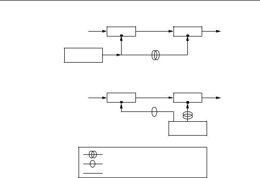
552 |
Ch. 13 Key Management Techniques |
|
(a) Symmetric-key encryption |
|
|
plaintext |
ciphertext |
plaintext |
encryption |
|
decryption |
secret key |
|
secret key |
symmetric |
|
|
key generator |
|
|
(b) Public-key encryption |
|
|
plaintext |
ciphertext |
plaintext |
encryption |
|
decryption |
public key |
|
private key |
asymmetric key pair generation
secure channel (privacy and authentication) secure channel (authentication only) unsecured channel (no protection)
Figure 13.4: Key management: symmetric-key vs. public-key encryption.
2.key-encrypting keys – symmetric keys or encryption public keys used for key transport or storage of other keys, e.g., in the key transport protocols of Chapter 12. These may also be called key-transport keys, and may themselves be secured under other keys.
3.data keys – used to provide cryptographic operations on user data (e.g., encryption, authentication). These are generally short-term symmetric keys; however, asymmetric signature private keys may also be considered data keys, and these are usually longer-term keys.
The keys at one layer are used to protect items at a lower level. This constraint is intended to make attacks more difficult, and to limit exposure resulting from compromise of a specific key, as discussed below.
13.8Note (protection of key-encrypting keys) Compromise of a key-encrypting key (and moreover, a master key as a special case thereof) affects all keys protected thereunder. Consequently, special measures are used to protect master keys, including severely limiting access and use, hardware protection, and providing access to the key only under shared control (§12.7.1).
13.9Example (key layering with master and terminal keys) Assume each terminal X from a predefined set shares a key-encrypting key (terminal key) KX with a trusted central node C, and that C stores an encrypted list of all terminal keys under a master key KM . C may then provide a session key to terminals X and Y as follows. C obtains a random value R
(possibly from an external source) and defines the session key to be S = DKM (R), the decryption of R under KM . Using KM , C decrypts the key list to obtain KX, computes S

§13.3 Techniques for distributing confidential keys |
553 |
from R, then encrypts S under KX and transmits it to X. S is analogously transmitted to Y , and can be recovered by both X and Y .
Cryptoperiods, long-term keys, and short-term keys
13.10Definition The cryptoperiod of a key is the time period over which it is valid for use by legitimate parties.
Cryptoperiods may serve to:
1.limit the information (related to a specific key) available for cryptanalysis;
2.limit exposure in the case of compromise of a single key;
3.limit the use of a particular technology to its estimated effective lifetime; and
4.limit the time available for computationally intensive cryptanalytic attacks (in applications where long-term key protection is not required).
In addition to the key layering hierarchy above, keys may be classified based on temporal considerations as follows.
1.long-term keys. These include master keys, often key-encrypting keys, and keys used to facilitate key agreement.
2.short-term keys. These include keys established by key transport or key agreement, and often used as data keys or session keys for a single communications session. See Remark 13.11.
In general, communications applications involve short-term keys, while data storage applications require longer-term keys. Long-term keys typically protect short-term keys. Diffie-Hellman keys are an exception in some cases (see §12.6.1). Cryptoperiods limit the use of keys to fixed periods, after which they must be replaced.
13.11Remark (short-term use vs. protection) The term short as used in short-term keys refers to the intended time of the key usage by legitimate parties, rather than the protection lifetime (cf. §13.7.1). For example, an encryption key used for only a single session might nonetheless be required to provide protection sufficient to withstand long-term attack (perhaps 20 years), whereas if signatures are verified immediately and never checked again, a signature key may need to provide protection only for a relatively short period of time. The more severe the consequences of a secret key being disclosed, the greater the reward to an adversary for obtaining access to it, and the greater the time or level of effort an adversary will invest to do so. (See also §12.2.2, and §12.2.3 on perfect forward secrecy.)
13.3.2 Key translation centers and symmetric-key certificates
Further to centralized key management discussed in §13.2.3, this section considers techniques involving key translation centers, including use of symmetric-key certificates.
(i) Key translation centers
A key translation center (KTC) T is a trusted server which allows two parties A and B, which do not directly share keying material, to establish secure communications through use of long-term keys KAT and KBT they respectively share with T . A may send a confidential message M to B using Protocol 13.12. If M is a key K, this provides a key transfer protocol (cf. §13.2.3); thus, KTCs provide translation of keys or messages.

554 |
Ch. 13 Key Management Techniques |
13.12Protocol Message translation protocol using a KTC
SUMMARY: A interacts with a trusted server (KTC) T and party B.
RESULT: A transfers a secret message M (or session key) to B. See Note 13.13.
1.Notation. E is a symmetric encryption algorithm. M may be a session key K.
2.One-time setup. A and T share key KAT . Similarly B and T share KBT .
3.Protocol messages.
A → T : |
A, EKAT (B, M) |
(1) |
A ← T : |
EKBT (M, A) |
(2) |
A → B : |
EKBT (M, A) |
(3) |
4.Protocol actions.
(a)A encrypts M (along with the identifier of the intended recipient) under KAT , and sends this to T with its own identifier (to allow T to look up KAT ).
(b)Upon decrypting the message, T determines it is intended for B, looks up the key (KBT ) of the indicated recipient, and re-encrypts M for B.
(c)T returns the translated message for A to send to (or post in a public site for) B; alternatively, T may send the response to B directly.
Only one of A and B need communicate with T . As an alternative to the protocol as given, A may send the first message to B directly, which B would then relay to T for translation, with T responding directly to B.
13.13Note (security of Protocol 13.12)
(i)The identifier A, corresponding to the key under which message (1) was encrypted, is included in message (2) as a secure indication (to B) of the original source. Key notarization (§13.5.2) offers a more robust method of preventing key substitution.
(ii)A recognizable distinction (e.g., re-ordering the message and identifier fields) between the format of messages (1) and (2) is required to prevent an adversary from reflecting (1) back to A as a message (3) purportedly originating from B.
(iii)Message replay is possible; attacks may be detected through the use of timestamps or sequence numbers within M. The protocol as given provides no entity authentication.
(iv)An integrity check mechanism on the encrypted text should be used to allow T to detect tampering of the cleartext identifier A in (1), as well as in (2) and (3).
(v)A chosen-text attack on key KBT in (2) may be prevented by an encryption mode such as CBC, and inserting an initial field containing a random number.
(ii) Symmetric-key certificates
Symmetric-key certificates provide a means for a KTC to avoid the requirement of either maintaining a secure database of user secrets (or duplicating such a database for multiple servers), or retrieving such keys from a database upon translation requests.
As before, associated with each party B is a key KBT shared with T , which is now embedded in a symmetric-key certificate EKT (KBT , B) encrypted under a symmetric master key KT known only to T . (A lifetime parameter L could also be included in the certificate as a validity period.) The certificate serves as a memo from T to itself (who alone can open it), and is given to B so that B may subsequently present it back to T precisely when required to access B’s symmetric key KBT for message translation. Rather than storing all user keys, T now need securely store only KT .

§13.4 Techniques for distributing public keys |
555 |
Symmetric-key certificates may be used in Protocol 13.12 by changing only the first message as below, where SCertA = EKT (KAT , A), SCertB = EKT (KBT , B):
A → T : SCertA, EKAT (B, M), SCertB (1)
A public database may be established with an entry specifying the name of each user and its corresponding symmetric-key certificate. To construct message (1), A retrieves B’s symm- etric-key certificate and includes this along with its own. T carries out the translation as before, retrieving KAT and KBT from these certificates, but now also verifies that A’s intended recipient B as specified in EKAT (B, M) matches the identifier in the supplied certificate SCertB.
13.14Remark (public-key functionality via symmetric techniques) The trusted third party functionality required when using symmetric-key certificates may be provided by per-user tamper-resistant hardware units keyed with a common (user-inaccessible) master key
KT . The trusted hardware unit HA of each user A generates a symmetric-key certificate SCertA = EKT (KAT , A), which is made available to B when required. HB decrypts the certificate to recover KAT (inaccessible to B) and the identity A (accessible to B). By design, HB is constrained to use other users’ keys KAT = KA solely for verification functions (e.g., MAC verification, message decryption). KA then functions as A’s public key (cf. Example 13.36), allowing data origin authentication with non-repudiation; an adjudicator may resolve disputes given a hardware unit containing KT , a disputed (message, signature) pair, and the authentic value SCertA from HA.
13.15Remark (symmetric-key vs. public-key certificates) Symmetric-key certificates differ from public-key certificates as follows: they are symmetric-key encrypted under T ’s master key (vs. signed using T ’s private key); the symmetric key within may be extracted only by T (vs. many parties being able to verify a public-key certificate); and T is required to be on-line for key translation (vs. an off-line certification authority). In both cases, certificates may be stored in a public directory.
13.4Techniques for distributing public keys
Protocols involving public-key cryptography are typically described assuming a priori possession of (authentic) public keys of appropriate parties. This allows full generality among various options for acquiring such keys. Alternatives for distributing explicit public keys with guaranteed or verifiable authenticity, including public exponentials for Diffie-Hellman key agreement (or more generally, public parameters), include the following.
1.Point-to-point delivery over a trusted channel. Authentic public keys of other users are obtained directly from the associated user by personal exchange, or over a direct channel, originating at that user, and which (procedurally) guarantees integrity and authenticity (e.g., a trusted courier or registered mail). This method is suitable if used infrequently (e.g., one-time user registration), or in small closed systems. A related method is to exchange public keys and associated information over an untrusted electronic channel, and provide authentication of this information by communicating a hash thereof (using a collision-resistant hash function) via an independent, lowerbandwidth authentic channel, such as a registered mail.

§13.4 Techniques for distributing public keys |
557 |
Binary trees
A binary tree is a structure consisting of vertices and directed edges. The vertices are divided into three types:
1.a root vertex. The root has two edges directed towards it, a left and a right edge.
2.internal vertices. Each internal vertex has three edges incident to it – an upper edge directed away from it, and left and right edges directed towards it.
3.leaves. Each leaf vertex has one edge incident to it, and directed away from it.
The vertices incident with the left and right edges of an internal vertex (or the root) are called the children of the internal vertex. The internal (or root) vertex is called the parent of the associated children. Figure 13.5 illustrates a binary tree with 7 vertices and 6 edges.
Root
Left Edge |
Right Edge |
Figure 13.5: A binary tree (with 4 shaded leaves and 3 internal vertices).
13.16Fact There is a unique directed path from any non-root vertex in a binary tree to the root vertex.
Constructing and using authentication trees
Consider a binary tree T which has t leaves. Let h be a collision-resistant hash function. T
can be used to authenticate t public values, Y1, Y2, . . . , Yt, by constructing an authentication tree T as follows.
1.Label each of the t leaves by a unique public value Yi.
2.On the edge directed away from the leaf labeled Yi, put the label h(Yi).
3.If the left and right edge of an internal vertex are labeled h1 and h2, respectively, label the upper edge of the vertex h(h1 h2).
4.If the edges directed toward the root vertex are labeled u1 and u2, label the root vertex h(u1 u2).
Once the public values are assigned to leaves of the binary tree, such a labeling is welldefined. Figure 13.6 illustrates an authentication tree with 4 leaves. Assuming some means to authenticate the label on the root vertex, an authentication tree provides a means to authenticate any of the t public leaf values Yi, as follows. For each public value Yi, there is a unique path (the authentication path) from Yi to the root. Each edge on the path is a left or right edge of an internal vertex or the root. If e is such an edge directed towards vertex x, record the label on the other edge (not e) directed toward x. This sequence of labels (the authentication path values) used in the correct order provides the authentication of Yi, as illustrated by Example 13.17. Note that if a single leaf value (e.g., Y1) is altered, maliciously or otherwise, then authentication of that value will fail.

558 |
|
Ch. 13 Key Management Techniques |
|
R = h(h2 h(Y4)) |
|
h2 = h(h1 h(Y3)) |
h(Y4) |
|
|
|
Y4 |
h1 = h(h(Y1) h(Y2)) |
|
h(Y3) |
|
|
|
h(Y1) |
|
Y3 |
h(Y2) |
||
Y1 Y2
Figure 13.6: An authentication tree.
13.17Example (key verification using authentication trees) Refer to Figure 13.6. The public
value Y1 can be authenticated by providing the sequence of labels h(Y2), h(Y3), h(Y4). The authentication proceeds as follows: compute h(Y1); next compute h1 = h(h(Y1)) h(Y2));
then compute h2 = h(h1 h(Y3)); finally, accept Y1 as authentic if h(h2 h(Y4)) |
= R, |
where the root value R is known to be authentic. |
|
The advantage of authentication trees is evident by considering the storage required to allow authentication of t public values using the following (very simple) alternate approach: an entity A authenticates t public values Y1, Y2, . . . , Yt by registering each with a trusted third party. This approach requires registration of t public values, which may raise storage issues at the third party when t is large. In contrast, an authentication tree requires only a single value be registered with the third party.
If a public key Yi of an entity A is the value corresponding to a leaf in an authentication tree, and A wishes to provide B with information allowing B to verify the authenticity of Yi, then A must (store and) provide to B both Yi and all hash values associated with the authentication path from Yi to the root; in addition, B must have prior knowledge and trust in the authenticity of the root value R. These values collectively guarantee authenticity, analogous to the signature on a public-key certificate. The number of values each party must store (and provide to others to allow verification of its public key) is lg(t), as per Fact 13.19.
13.18Fact (depth of a binary tree) Consider the length of (or number of edges in) the path from each leaf to the root in a binary tree. The length of the longest such path is minimized when the tree is balanced, i.e., when the tree is constructed such that all such paths differ in length by at most one. The length of the path from a leaf to the root in a balanced binary tree containing t leaves is about lg(t).
13.19Fact (length of authentication paths) Using a balanced binary tree (Fact 13.18) as an authentication tree with t public values as leaves, authenticating a public value therein may be achieved by hashing lg(t) values along the path to the root.
13.20Remark (time-space tradeoff ) Authentication trees require only a single value (the root value) in a tree be registered as authentic, but verification of the authenticity of any particular leaf value requires access to and hashing of all values along the authentication path from leaf to root.
13.21Remark (changing leaf values) To change a public (leaf) value or add more values to an authentication tree requires recomputation of the label on the root vertex. For large balanced

§13.4 Techniques for distributing public keys |
559 |
trees, this may involve a substantial computation. In all cases, re-establishing trust of all users in this new root value (i.e., its authenticity) is necessary.
The computational cost involved in adding more values to a tree (Remark 13.21) may motivate constructing the new tree as an unbalanced tree with the new leaf value (or a subtree of such values) being the right child of the root, and the old tree, the left. Another motivation for allowing unbalanced trees arises when some leaf values are referenced far more frequently than others.
13.4.2 Public-key certificates
Public-key certificates are a vehicle by which public keys may be stored, distributed or forwarded over unsecured media without danger of undetectable manipulation. The objective is to make one entity’s public key available to others such that its authenticity (i.e., its status as the true public key of that entity) and validity are verifiable. In practice, X.509 certificates are commonly used (see page 587). Further details regarding public-key certificates follow.
13.22Definition A public-key certificate is a data structure consisting of a data part and a signature part. The data part contains cleartext data including, as a minimum, a public key and a string identifying the party (subject entity) to be associated therewith. The signature part consists of the digital signature of a certification authority over the data part, thereby binding the subject entity’s identity to the specified public key.
The Certification Authority (CA) is a trusted third party whose signature on the certificate vouches for the authenticity of the public key bound to the subject entity. The significance of this binding (e.g., what the key may be used for) must be provided by additional means, such as an attribute certificate or policy statement. Within the certificate, the string which identifies the subject entity must be a unique name within the system (distinguished name), which the CA typically associates with a real-world entity. The CA requires its own signature key pair, the authentic public key of which is made available to each party upon registering as an authorized system user. This CA public key allows any system user, through certificate acquisition and verification, to transitively acquire trust in the authenticity of the public key in any certificate signed by that CA.
Certificates are a means for transferring trust, as opposed to establishing trust originally. The authenticity of the CA’s public key may be originally provided by non-cryptogra- phic means including personal acquisition, or through trusted couriers; authenticity is required, but not secrecy.
Examples of additional information which the certificate data part might contain include:
1.a validity period of the public key;
2.a serial number or key identifier identifying the certificate or key;
3.additional information about the subject entity (e.g., street or network address);
4.additional information about the key (e.g., algorithm and intended use);
5.quality measures related to the identification of the subject entity, the generation of the key pair, or other policy issues;
6.information facilitating verification of the signature (e.g., a signature algorithm identifier, and issuing CA’s name);
7.the status of the public key (cf. revocation certificates, §13.6.3).
560 |
Ch. 13 Key Management Techniques |
(i) Creation of public-key certificates
Before creating a public-key certificate for a subject entity A, the certification authority should take appropriate measures (relative to the security level required, and customary business practices), typically non-cryptographic in nature, to verify the claimed identity of A and the fact that the public key to be certified is actually that of A. Two cases may be distinguished.
Case 1: trusted party creates key pair. The trusted party creates a public-key pair, assigns it to a specific entity, and includes the public key and the identity of that entity in the certificate. The entity obtains a copy of the corresponding private key over a secure (authentic and private) channel after proving its identity (e.g., by showing a passport or trusted photo-id, in person). All parties subsequently using this certificate essentially delegate trust to this prior verification of identity by the trusted party.
Case 2: entity creates own key pair. The entity creates its own public-key pair, and securely transfers the public key to the trusted party in a manner which preserves authenticity (e.g., over a trusted channel, or in person). Upon verification of the authenticity (source) of the public key, the trusted party creates the public-key certificate as above.
13.23Remark (proof of knowledge of private key) In Case 2 above, the certification authority should require proof of knowledge of the corresponding private key, to preclude (among other possible attacks) an otherwise legitimate party from obtaining, for malicious purposes, a public-key certificate binding its name to the public key of another party. For the case of signature public keys, this might be done by the party providing its own signature on a sub-
set of the data part of the certificate; or by responding to a challenge r1 randomized by the party itself e.g., signing h(r1||r2) for an appropriate hash function h and a random number r2 chosen by the signer.
(ii) Use and verification of public-key certificates
The overall process whereby a party B uses a public-key certificate to obtain the authentic public key of a party A may be summarized as follows:
1.(One-time) acquire the authentic public key of the certification authority.
2.Obtain an identifying string which uniquely identifies the intended party A.
3.Acquire over some unsecured channel (e.g. from a central public database of certificates, or from A directly), a public-key certificate corresponding to subject entity A and agreeing with the previous identifying string.
4.(a) Verify the current date and time against the validity period (if any) in the certificate, relying on a local trusted time/day-clock;
(b)Verify the current validity of the CA’s public key itself;
(c)Verify the signature on A’s certificate, using the CA’s public key;
(d)Verify that the certificate has not been revoked (§13.6.3).
5.If all checks succeed, accept the public key in the certificate as A’s authentic key.
13.24Remark (life cycle reasons for single-key certificates) Due to differing life cycle requirements for different types of keys (e.g., differing cryptoperiods, backup, archival, and other lifetime protection requirements – see §13.7), separate certificates are recommended for separate keys, as opposed to including several keys in a single certificate. See also Remark 13.32.

§13.4 Techniques for distributing public keys |
561 |
(iii) Attribute certificates
Public-key certificates bind a public key and an identity, and include additional data fields necessary to clarify this binding, but are not intended for certifying additional information. Attribute certificates are similar to public-key certificates, but specifically intended to allow specification of information (attributes) other than public keys (but related to a CA, entity, or public key), such that it may also be conveyed in a trusted (verifiable) manner. Attribute certificates may be associated with a specific public key by binding the attribute information to the key by the method by which the key is identified, e.g., by the serial number of a corresponding public-key certificate, or to a hash-value of the public key or certificate.
Attribute certificates may be signed by an attribute certification authority, created in conjunction with an attribute registration authority, and distributed in conjunction with an attribute directory service (cf. Figure 13.3). More generally, any party with a signature key and appropriate recognizable authority may create an attribute certificate. One application is to certify authorization information related to a public key. More specifically, this may be used, for example, to limit liability resulting from a digital signature, or to constrain the use of a public key (e.g., to transactions of limited values, certain types, or during certain hours).
13.4.3 Identity-based systems
Identity-based systems resemble ordinary public-key systems, involving a private transformation and a public transformation, but users do not have explicit public keys as before. Instead, the public key is effectively replaced by (or constructed from) a user’s publicly available identity information (e.g., name and network or street address). Any publicly available information which uniquely identifies a user and can be undeniably associated with the user, may serve as the identity information.
13.25Definition An identity-based cryptographic system (ID-based system) is an asymmetric system wherein an entity’s public identification information (unique name) plays the role of its public key, and is used as input by a trusted authority T (along with T ’s private key) to compute the entity’s corresponding private key.
After computing it, T transfers the entity’s private key to the entity over a secure (authentic and private) channel. This private key is computed from not only the entity’s identity information, but must also be a function of some privileged information known only to T (T ’s private key). This is necessary to prevent forgery and impersonation – it is essential that only T be able to create valid private keys corresponding to given identification information. Corresponding (authentic) publicly available system data must be incorporated in the cryptographic transformations of the ID-based system, analogous to the certification authority’s public key in certificate-based systems. Figure 13.7(b) on page 564 illustrates the design of an identity-based system. In some cases, additional system-defined public data DA must be associated with each user A in addition to its a priori identity IDA (see Remark 13.27); such systems are no longer “purely” identity-based, although neither the authenticity of DA nor IDA need be explicitly verified.
13.26Remark (authenticity in ID-based systems) ID-based systems differ from public-key systems in that the authenticity of user-specific public data is not (and need not be) explicitly verified, as is necessary for user public keys in certificate-based systems. The inherent redundancy of user public data in ID-based systems (derived through the dependence of the corresponding private key thereon), together with the use of authentic public system data,

562 |
Ch. 13 Key Management Techniques |
implicitly protects against forgery; if incorrect user public data is used, the cryptographic transformations simply fail. More specifically: signature verification fails, entity authentication fails, public-key encryption results in undecipherable text, and key-agreement results in parties establishing different keys, respectively, for (properly constructed) identity-based signature, authentication, encryption, and key establishment mechanisms.
The motivation behind ID-based systems is to create a cryptographic system modeling an ideal mail system wherein knowledge of a person’s name alone suffices to allow mail to be sent which that person alone can read, and to allow verification of signatures that person alone could have produced. In such an ideal cryptographic system:
1.users need exchange neither symmetric keys nor public keys;
2.public directories (files of public keys or certificates) need not be kept; and
3.the services of a trusted authority are needed solely during a set-up phase (during which users acquire authentic public system parameters, to be maintained).
13.27Remark (ideal vs. actual ID-based systems) A drawback in many concrete proposals of ID-based systems is that the required user-specific identity data includes additional data (an
integer or public data value), denoted DA in Figure 13.7(b), beyond an a priori identity IDA. For example, see Note 10.29(ii) on Feige-Fiat-Shamir identification. Ideally, DA is not required, as a primary motivation for identity-based schemes is to eliminate the need to transmit public keys, to allow truly non-interactive protocols with identity information itself sufficing as an authentic public key. The issue is less significant in signature and identification schemes where the public key of a claimant is not required until receiving a message from that claimant (in this case DA is easily provided); but in this case, the advantage of identity-based schemes diminishes. It is more critical in key agreement and public-key encryption applications where another party’s public key is needed at the outset. See also Remark 13.31.
13.28Example (ID-based system implemented using chipcards) A simplified ID-based system based on chipcards may be run as follows. A third party T , acting as a trusted key generation system, is responsible solely for providing each user a chipcard during a set-up phase, containing that party’s ID-based private key, after carrying out a thorough identity check. If no further users need be added, T may publish the public system data and cease to exist.
Users are responsible for not disclosing their private keys or losing their cards. |
|
13.4.4 Implicitly-certified public keys
Another variation of public-key systems is asymmetric systems with implicitly-certified public keys. Here explicit user public keys exist (see Figure 13.7(c)), but they must be reconstructed rather than transported by public-key certificates as per certificate-based systems. For other advantages, see Remark 13.30. Examples of specific such mechanisms are given in §12.6.2. Systems with implicitly-certified public keys are designed such that:
1.Entities’ public keys may be reconstructed (by other parties) from public data (which essentially replace a certificate).
2.The public data from which a public key is reconstructed includes:
(a)public (i.e., system) data associated with a trusted party T ;
(b)the user entity’s identity (or identifying information, e.g., name and address);
(c)additional per-user public data (reconstruction public data).

§13.4 Techniques for distributing public keys |
563 |
3.The integrity of a reconstructed public key is not directly verifiable, but a “correct” public key can be recovered only from authentic user public data.
Regarding authenticity of reconstructed public keys, the system design must guarantee:
1.Alteration of either a user’s identity or reconstruction public data results in recovery of a corrupted public key, which causes denial of service but not cryptographic exposure (as per Remark 13.26).
2.It is computationally infeasible for an adversary (without knowledge of T ’s private data) to compute a private key corresponding to any party’s public key, or to construct a matching user identity and reconstruction public data for which a corresponding private key may also be computed. Reconstructed public keys are thus implicitly authenticated by construction.
13.29Remark (applications of implicitly-certified keys) Implicitly-certified public keys may be used as an alternate means for distributing public keys (e.g., Diffie-Hellman keys – see §12.6.3) in various key agreement protocols, or in conjunction with identification protocols, digital signature schemes, and public-key encryption schemes.
Classes of implicitly-certified public keys
Two classes of implicitly-certified public keys may be distinguished:
1.identity-based public keys (Class 1). The private key of each entity A is computed by a trusted party T , based on A’s identifying information and T ’s private key; it is also a function of A’s user-specific reconstruction public data, which is fixed a priori by T . A’s private key is then securely transferred by T to A. An example is Mechanism 12.59.
2.self-certified public keys (Class 2). Each entity A itself computes its private key and corresponding public key. A’s reconstruction public data (rather than A’s private key, as in Class 1) is computed by T as a function of the public key (transferred to T by A), A’s identifying information, and T ’s private key. An example is Mechanism 12.61.
Class 1 requires more trust in the third party, which therein has access to users’ private keys. This differs from Class 2, as emphasized by the term “self” in “self-certified”, which refers to the knowledge of this key being restricted to the entity itself.
13.4.5 Comparison of techniques for distributing public keys
§13.4 began with an overview of techniques for addressing authenticity in public key distribution. The basic approaches of §13.4.2, §13.4.3, and §13.4.4 are discussed further here. Figure 13.7 illustrates corresponding classes of asymmetric signature systems, contrasting public-key systems (with explicit public keys), identity-based systems (the public key is a user’s identity information), and systems with implicitly-certified public keys (an explicit public key is reconstructed from user public data).4 The main differences are as follows:
1.Certificate-based public-key systems have explicit public keys, while ID-based systems do not; in implicitly-certified systems explicit public keys are reconstructed. The explicit public key in public-key systems (Figure 13.7(a)) is replaced by:
(a)the triplet (DA, IDA, PT ) for identity-based systems (Figure 13.7(b)). IDA is an identifying string for A, DA is additional public data (defined by T and related to IDA and A’s private key), and PT consists of the trusted public key (or system parameters) of a trusted authority T .
4While the figure focuses (for concreteness) on signature systems, concepts carry over analogously for asymmetric entity authentication, key establishment, and encryption systems.


566 |
Ch. 13 Key Management Techniques |
(b)the triplet (RA, IDA, PT ) for systems with implicitly-certified public keys (Figure 13.7(c)). In this case, an explicit public key PA is reconstructed from these parameters. The reconstruction public data RA plays a role analogous to the public data DA in Figure 13.7(b).
2.The authenticity of public keys can (and must) be explicitly verified in certificatebased systems, but not (and need not) in ID-based or implicitly-certified systems.
3.The trusted authority need not know users’ private keys in certificate-based publickey systems or implicitly-certified systems with self-certified public keys; but does in ID-based systems, and in implicitly-certified systems with ID-based keys.
4.Similar to identity-based systems (§13.4.3), implicitly-certified public keys (of both classes) depend on an entity’s identifying information, and in this sense are also “identity-based”. However, ID-based systems avoid explicit public keys entirely (a user’s identity data is essentially its public key), while implicitly-certified public keys are not restricted to user identities and may be explicitly computed (and thus more easily used in conjunction with ordinary public-key schemes).
5.The two classes of implicitly-certified public keys (Figure 13.7(c)) differ in their relationship between users’ reconstruction public data and private keys as follows.
(a)Class 1: a user’s private key is computed as a function of the reconstruction data, and this private key is computed by the trusted authority;
(b)Class 2: the reconstruction data is computed as a function of the user’s public key, and the corresponding private key is computed by the party itself.
6.In all three approaches, at some stage a third party which is trusted to some level (cf. Note 13.7) is required to provide a link transferring trust between users who may have never met each other and may share nothing in common other than authentic system parameters (and possibly knowledge of other users’ identities).
13.30Remark (implicitly-certified public keys vs. public-key certificates) Advantages of implic- itly-certified public keys over public-key certificates include: possibly reduced space requirements (signed certificates require storage for signatures); possible computational savings (signature verification, as required for certificates, is avoided); and possible communications savings (e.g. if identity-based and the identity is known a priori). Countering these points, computation is actually required to reconstruct a public key; and additional reconstruction public data is typically required.
13.31Remark (key revocation in ID-based systems) Revocation of public keys may be addressed in ID-based schemes and systems using implicitly-certified public keys by incorporating information such as a key validity period or serial number into the identification string used to compute an entity’s public key (cf. Remark 13.27). The revocation issue is then analogous to that for public-key certificates. Additional information, e.g., pertaining to key usage or an associated security policy, may similarly be incorporated.

§13.5 Techniques for controlling key usage |
567 |
13.5 Techniques for controlling key usage
This section considers techniques for restricting keys to pre-authorized uses.
13.5.1 Key separation and constraints on key usage
Information that may be associated with cryptographic keys includes both attributes which restrict their use, and other information of operational use. These include:
1.owner of key
2.validity period (intended cryptoperiod)
3.key identifier (allowing non-cryptographic reference to the key)
4.intended use (see Table 13.2 for a coarse selection)
5.specific algorithm
6.system or environment of intended use, or authorized users of key
7.names of entities associated with key generation, registration, and certification
8.integrity checksum on key (usually part of authenticity requirement)
Key separation and the threat of key misuse
In simple key management systems, information associated with keys, including authorized uses, are inferred by context. For additional clarity or control, information explicitly specifying allowed uses may accompany distributed keys and be enforced by verification, at the time of use, that the attempted uses are authorized. If control information is subject to manipulation, it should be bound to the key by a method which guarantees integrity and authenticity, e.g., through signatures (cf. public-key certificates) or an encryption technique providing data integrity.
The principle of key separation is that keys for different purposes should be cryptographically separated (see Remark 13.32). The threat of key misuse may be addressed by techniques which ensure that keys are used only for those purposes pre-authorized at the time of key creation. Restrictions on key usage may be enforced by procedural techniques, physical protection (tamper-resistant hardware), or cryptographic techniques as discussed below.
Discussion of other methods in §13.5.2 includes key tags, which allow key separation with explicitly-defined uses; key variants, which separate keys without explicitly defining authorized uses; and key notarization and control vectors, which bind control information into the process by which keys are derived.
13.32Remark (cryptographic reasons for key separation) A principle of sound cryptographic design is to avoid use of the same cryptographic key for multiple purposes. A key-encrypt- ing key should not be used interchangeably as a data encryption key, since decrypted keys are not generally made available to application programs, whereas decrypted data is. Distinct asymmetric encryption and signature keys are also generally used, due to both differing life cycle requirements and cryptographic prudence. Flaws also potentially arise if: asymmetric keys are used for both signatures and challenge-response entity authentication (Remark 10.40); keys are used for both encryption and challenge-response entity authentication (chosen-text attacks); symmetric keys are used for both encryption and message authentication (Example 9.88). See also Remark 13.24.

568 |
Ch. 13 Key Management Techniques |
13.5.2 Techniques for controlling use of symmetric keys
The main technique discussed below is the use of control vectors. For historical context, key tags/key variants and key notarization are also discussed.
(i) Key tags and key variants
Key tags provide a simplified method for specifying allowed uses of keys (e.g., data-encryp- ting vs. key-encrypting keys). A key tag is a bit-vector or structured field which accompanies and remains associated with a key over its lifetime. The tag bits are encrypted jointly with the key and thereby bound to it, appearing in plaintext form only when the key is decrypted. If the combination of tag bits and key are sufficiently short to allow encryption in a single block operation (e.g., a 56-bit key with an 8-bit tag for a 64-bit block cipher), then the inherent integrity provided by encryption precludes meaningful manipulation of the tag.
A naive method for providing key separation is to derive separate keys from a single base key (or derivation key) using additional non-secret parameters and a non-secret function. The resulting keys are called key variants or derived keys.
One technique for varying keys is key offsetting, whereby a key-encrypting key K is modified on a per-use basis by a counter N incremented after each use. This may prevent replay of encrypted keys. The modified key K N is used to encrypt another (e.g., session) key. The recipient likewise modifies K to decrypt the session key. A second technique, complementing alternate 4-bit blocks of K commencing with the first 4 bits, is a special case of fixed-mask offsetting (Example 13.33).
13.33Example (key variants using fixed-mask offsets) Suppose exactly three classes of keys are desired. Construct keys by using variations K1 and K2 of a master key K, with K1 =
K v1, K2 = K v2, and v1, v2 nonsecret mask values. Using K, K1, and K2 to encrypt other keys then allows key separation of the latter into three classes.
If the derivation process is invertible, the base key can be recovered from the derived key. Ideally, the derivation technique is non-reversible (one-way), implying that compromise of one derived key would not compromise the base key or other derived keys (cf. §13.7.1 on security impacts of related keys). Yet another example of key derivation (see §12.3.1) has this property: compute Ki = EK(ri) where ri is a random number, or replace the encryption function E by a MAC, or simply hash K and ri using a hash function h with suitable properties.
(ii) Key notarization
Key notarization is a technique intended to prevent key substitution by requiring explicit specification of the identities of parties involved in a keying relationship. A key is authenticated with respect to these identities (preventing impersonation) by modifying a keyencrypting key such that the correct identities must be specified to properly recover the protected key. The key is said to be sealed with these identities. Preventing key substitution is a requirement in all (authenticated) key establishment protocols. Notarization requires proper control information for accurate recovery of encrypted keys, providing implicit protection analogous to implicitly-certified public keys (§13.4.4).
The basic technique (simple key notarization) involves a trusted server (notary), or one of the parties sharing the key, using a key-encrypting key K to encrypt a session key S, intended for use with the originating party i and the recipient j, as: EK (i||j)(S). Here i and j are assumed to identify unique entities in the given system. The party intending to recover
§13.5 Techniques for controlling key usage |
569 |
S from this must share K and explicitly specify i and j in the correct order, otherwise a random key will be recovered. The analogy to a notary originated from the assumption that the third party properly authenticates the identities of the intended parties, and then provides a session key which may only be recovered by these parties. A more involved process, key notarization with offsetting, is given in Example 13.34
13.34Example (key notarization with offsetting) Let E be a block cipher operating on 64-bit blocks with 64-bit key, K = KL||KR be a 128-bit key-encrypting key, N a 64-bit counter, and i = iL||iR, j = jL||jR 128-bit source and destination identifiers. For key notarization
with offsetting, compute: K1 = EKR iL(jR) KL N, K2 = EKL jL(iR) KR N. The resulting 128-bit notarized key (K1, K2) then serves as a key-encrypting key in twokey triple-encryption. The leftmost terms f1(KR, i, j) and f2(KL, i, j) in the computation of K1, K2 above are called notary seals, which, when combined with KL and KR, respectively, result in quantities analogous to those used in simple key notarization (i.e., functions
of K, i, j). For K a 64-bit (single-length) key, the process is modified as follows: using KL = KR = K, compute the notary seals f1(KR, i, j), f2(KL, i, j) as above, concatenate the leftmost 32 bits of f1 with the rightmost of f2 to obtain f, then compute f K N as
the notarized key. |
|
(iii) Control vectors
While key notarization may be viewed as a mechanism for establishing authenticated keys, control vectors provide a method for controlling the use of keys, by combining the idea of key tags with the mechanism of simple key notarization. Associated with each key S is a control vector C, which is a data field (similar to a key tag) defining the authorized uses of the key (effectively typing the key). It is bound to S by varying a key-encrypting key K before encryption: EK C(S).
Key decryption thus requires the control vector be properly specified, as well as the correct key-encrypting key; if the combined quantity K C is incorrect, a spurious key of no advantage to an adversary is recovered. Cryptographically binding the control vector C to S at the time of key generation prevents unauthorized manipulation of C, assuming only authorized parties have access to the key-encrypting key K.
Control vectors may encompass key notarization by using one or more fields in C to specify identities. In relation to standard models for access control (Note 13.35), a control vector may be used to specify a subject’s identity (Si) and privileges (Ai,j) regarding the use of a key (Kj).
At time of use for a specific cryptographic operation, the control vector is input as well as the protected key. At this time, a check is made that the requested operation complies with the control vector; if so, the key is decrypted using the control vector. If the control vector does not match that bound to the protected key (or if K is incorrect), the recovered key S =S will be spurious. Security here is dependent on the assumption that checking is inseparable from use, and done within a trusted subsystem.
If the bitsize of the control vector C differs from that of the key K, a collision-resistant hash function may be used prior to coupling. This allows arbitrary length control vectors. Thus a 128-bit key K and a hash function h with 128-bit output may be used to encrypt S as: EK h(C)(S).
13.35Note (models for access control) Several methods are available to control access to resources. The access matrix model uses a 2-dimensional matrix Ai×j with a row for each subject (Si) and a column for each object (Oj), and relies on proper identification of subjects Si. Each access record Ai,j specifies the privileges entity Si has on object Oj (e.g.,

570 |
Ch. 13 Key Management Techniques |
an application program may have read, write, modify, or execute privileges on a file). Column j may alternately serve as an access list for object Oj, having entries (Si, Pij) where Pij = Ai,j specifies privileges. Another method of resource protection uses the idea of capabilities: a capability (O, P ) specifies an object O and privilege set P related to O, and functions as a ticket – possession of capability (O, P ) grants the holder the specified privileges, without further validation or ticket-holder identification.
13.36Example (sample uses of control vectors) Control vectors may be used to provide a public-key like functionality as follows (cf. Remark 13.14). Two copies of a symmetric key are distributed, one typed to allow encryption only (or MAC generation), and a second allowing decryption only (or MAC verification). Other sample uses of control fields include: allowing random number generation; allowing ciphertext translation (e.g., in KTCs); dis-
tinguishing data encryption and key encryption keys; or incorporation of any field within a public-key certificate.
13.37Remark (key verification and preventing replay) Replay of keys distributed by key transport protocols may be countered by the same techniques used to provide uniqueness/timeliness and prevent replay of messages – sequence numbers, timestamps, and challenge-response techniques (§10.3.1). Before a key resulting from a key derivation, notarization, or control vector technique is actually used, verification of its integrity may be desirable (cf. key confirmation, §12.2). This can be achieved using standard techniques for data integrity (Figure 9.8). A simple method involves the originator sending the encryption (under the key in question) of a data item which the recipient can recognize.
13.6Key management involving multiple domains
This section considers key management models for systems involving multiple domains or authorities, as opposed to the simpler single-domain models of §13.2.3.
13.38Definition A security domain (domain) is defined as a (sub)system under the control of a single authority which the entities therein trust. The security policy in place over a domain is defined either implicitly or explicitly by its authority.
The trust that each entity in a domain has in its authority originates from, and is maintained through, an entity-specific shared secret key or password (in the symmetric case), or possession of the authority’s authentic public key (in the asymmetric case). This allows secure communications channels (with guaranteed authenticity and/or confidentiality) to be established between the entity and authority, or between two entities in the same domain. Security domains may be organized (e.g., hierarchically) to form larger domains.
13.6.1 Trust between two domains
Two parties A and B, belonging to distinct security domains DA and DB with respective trusted authorities TA and TB, may wish to communicate securely (or A may wish to access resources from a distinct domain DB). This can be reduced to the requirement that A and B either:

§13.6 Key management involving multiple domains |
571 |
1.(share a symmetric key) establish a shared secret key KAB which both trust as being known only to the other (and possibly trusted authorities); or
2.(share trusted public keys) acquire trust in one or more common public keys which may be used to bridge trust between the domains, e.g., allowing verification of the authenticity of messages purportedly from the other, or ensure the confidentiality of messages sent to the other.
Either of these is possible provided TA and TB have an existing trust relationship, based on either trusted public keys or shared secret keys.
If TA and TB do have an existing trust relationship, either requirement may be met by using this and other initial pairwise trust relationships, which allow secure communications channels between the pairs (A, TA), (TA, TB), and (TB, B), to be successively used to establish the objective trust relationship (A, B). This may be done by A and B essentially delegating to their respective authorities the task of acquiring trust in an entity under the other authority (as detailed below).
If TA and TB do not share an existing trust relationship directly, a third authority TC, in which they both do trust, may be used as an intermediary to achieve the same end result. This is analogous to a chain of trust in the public-key case (§13.6.2). The two numbered options beginning this subsection are now discussed in further detail.
Domain DA |
|
|
Domain DB |
|
||||||
|
|
|
|
|
|
(2) |
|
|
|
|
|
|
Authority |
|
|
Authority |
|
||||
|
|
|
TA |
|
|
|
TB |
|
||
(1) |
|
|
(3A) |
|
|
|
|
(3B) |
|
|
|
|
|
|
|
|
|
||||
|
|
|
|
|
|
(4) |
|
|
|
|
|
|
|
|
|
|
|
|
|
|
|
|
|
|
Party A |
|
|
Party B |
|
|||
|
|
|
|
|
|
|
||||
|
|
|
|
|
|
|
||||
|
|
|
|
|
|
|
|
|
|
|
|
|
|
|
|
|
|
|
|
|
|
Figure 13.8: Establishing trust between users in distinct domains.
1.trusted symmetric key: Trust in a shared secret key may be acquired through a variety of authenticated key establishment techniques (see §12.3 for detailed protocols). An outline of steps by which parties A and B above may do so follows, with reference to Figure 13.8.
(a)A makes a request to TA to obtain a key to share with B (1).
(b)TA and TB establish a short-term secret key KAB (2).
(c)TA and TB, respectively, distribute KAB to A and B, guaranteeing secrecy and authenticity (3A, 3B).
(d)A uses KAB for secure direct communications with B (4). Message (3B) may be eliminated if its contents are relayed by TB to A via TA as part of the existing messages (2), (3A).
In this case, from A’s viewpoint the composition of TA, TB and the trust relationship (TA, TB) may be seen as a single (composite) authority, which A communicates with through TA, and which plays the role of the (simple) authority in the standard case of a KDC or KTC (see §13.2.3).

572 |
Ch. 13 Key Management Techniques |
2.trusted public key: Trust in a public key may be acquired, based on existing trust relationships, through data origin authentication by standard techniques such as digital signatures or message authentication codes. A may acquire the trusted public key of party B described above as follows (cf. Figure 13.8).
(a)A requests from TA the trusted public key of user B (1).
(b)TA acquires this from TB, with guaranteed authenticity (2).
(c)TA transfers this public key to A, with guaranteed authenticity (3A).
(d)A uses this public key to secure direct communications with B (4).
13.39Definition A cross-certificate (or CA-certificate) is a certificate created by one certification authority (CA), certifying the public key of another CA.
13.40Remark (user-specific vs. domain cross-trust) Method 2 above transfers to A trust specifically in the public key of B; this may be called a user-specific transfer of trust. Alternatively, a general transfer of trust between domains is possible as follows, assuming TB has created a certificate CB containing the identity and public key of B. In this case, TA creates a cross-certificate containing the identity and public key of TB. A, possessing the trusted signature verification key of TA, may verify the signature on this latter certificate, thereby acquiring trust in TB’s signature verification key, and allowing A to verify and thereby trust B’s public key within CB (or the public key in any other certificate signed by TB). Thus, user A from domain DA (with authority TA) acquires trust in public keys certified in DB by TB.
13.6.2 Trust models involving multiple certification authorities
Many alternatives exist for organizing trust relationships between certification authorities (CAs) in public-key systems involving multiple CAs. These are called trust models or certification topologies, and are logically distinct from (although possibly coincident with) communications models. (In particular, a communications link does not imply a trust relationship.) Trust relationships between CAs determine how certificates issued by one CA may be utilized or verified by entities certified by distinct CAs (in other domains). Before discussing various trust models, certificate chains are first introduced.
(i) Certificate chains and certification paths
Public-key certificates provide a means for obtaining authenticated public keys, provided the verifier has a trusted verification public key of the CA which signed the certificate. In the case of multiple certification authorities, a verifier may wish to obtain an authentic public key by verifying a certificate signed by a CA other than one for which it (originally) possesses a trusted public key. In this case, the verifier may still do so provided a chain of certificates can be constructed which corresponds to an unbroken chain of trust from the CA public key which the verifier does trust, to the public key it wishes to obtain trust in.
Certificate chains correspond to directed paths in the graphical representation of a CA trust model (see Figure 13.9). The goal is to find a sequence of certificates corresponding to a directed path (certification path) starting at the node corresponding to the CA whose public key a verifier trusts a priori, and ending at the CA which has signed the certificate of the public key to be verified.
13.41Example (illustration of certificate chain) Consider Figure 13.9(e) on page 574. Suppose an entity A in possession of the public key P5 of CA5 wishes to verify the certificate of an
§13.6 Key management involving multiple domains |
573 |
entity B signed by CA3, and thereby obtain trust in PB. A directed path (CA5, CA4, CA3) exists. Let CA5{CA4} denote a certificate signed by CA5 binding the name CA4 to the public key P4. Then the certificate chain (CA5{CA4}, CA4{CA3}), along with initial trust in P5, allows A to verify the signature on CA5{CA4} to extract a trusted copy of P4, use P4 to verify the signature on CA4{CA3} to extract a trusted copy of P3, and then use P3 to verify the authenticity of (the certificate containing) PB.
Given an initial trusted public key and a certificate to be verified, if a certificate chain is not provided to the verifier, a method is required to find (build) the appropriate chain from publicly available data, prior to actual cryptographic chain verification. This noncryptographic task resembles that of routing in standard communications networks.
13.42Example (building certificate chains using cross-certificate pairs) One search technique for finding the certification path given in Example 13.41 involves cross-certificate pairs. In a public directory, in the directory entry for each CA X, for every CA Y that either cross-certifies X or that X cross-certifies, store the certificate pair (forward, reverse) = (CAY {CAX}, CAX{CAY }), called a cross-certificate pair. Here notation is as in Example 13.41, the pair consists of the forward and reverse certificates of CAX (see page 575), and at least one of the two certificates is present. In the absence of more advanced tech-
niques or routing tables, any existent certification path could be found by depth-first or breadth-first search of the reverse certificates in cross-certificate pairs starting at the CA whose public key the verifier possesses initially.
As part of signature verification with certificate chains, verification of cross-certificates requires checking they themselves have not been revoked (see §13.6.3).
(ii) Trust with separate domains
Figure 13.9 illustrates a number of possible trust models for certification, which are discussed below, beginning with the case of separated domains.
Simple public-key systems involve a single certification authority (CA). Larger systems involve two or more CAs. In this case, a trust relationship between CAs must be specified in order for users under different CAs to interoperate cryptographically. By default, two distinct CAs define separate security domains as in Figure 13.9(a), with no trust relationship between domains. Users in one domain are unable to verify the authenticity of certificates originating in a separate domain.
(iii) Strict hierarchical trust model
The first solution to the lack of cryptographic interoperability between separate domains is the idea of a strict hierarchy, illustrated by Figure 13.9(b). Each entity starts with the public key of the root node – e.g., entity E1(1) is now given CA5’s public key at registration, rather than that of CA1 as in figure (a). This model is called the rooted chain model, as all trust chains begin at the root. It is a centralized trust model.
Several such rooted trees, each being a strict hierarchy, may be combined in a trust model supporting multiple rooted trees as in Figure 13.9(c). In this case, a cross-certificate is allowed between the roots of the trees, illustrated by a bi-directional arrow between roots. The arrow directed from CAX to CAY denotes a certificate for the public key of CAY created by CAX. This allows users in the tree under CAX to obtain trust in certificates under CAY through certificate chains which start at CAX and cross over to CAY .
In the strict hierarchical model, all entities are effectively in a single domain (defined by the root). Despite the fact that, for example, CA1 signs the public-key certificate of E1(1),

§13.6 Key management involving multiple domains |
575 |
E1(1) trusts the root (CA5) directly but not CA1. E1(1) trusts CA1 only indirectly through the root. Potential drawbacks of this model include:
1.all trust in the system is dependent on the root key
2.certificate chains are required even for two entities under the same CA
3.certificate chains become long in deep hierarchies
4.a more natural model in some organizations is for trust to begin at a local node (the parent CA) rather than a distant node (the root).
(iv)Reverse certificates and the general digraph trust model
A more general hierarchical model, a hierarchy with reverse certificates, is illustrated in Figure 13.9(d). This resembles the strict hierarchy of Figure 13.9(b), but now each CA lower in the hierarchy also creates certificates certifying the public keys of its directly superior (parent) CA. Two types of certificates may then be distinguished in a hierarchy:
1.forward certificate. A forward certificate (relative to CAX) is created by the CA directly above CAX signing the public key of CAX, and illustrated in the hierarchy by a downward arrow towards CAX.
2.reverse certificate. A reverse certificate (relative to CAX) is created by CAX signing the public key of its immediately superior CA, and illustrated in the hierarchy by an upward arrow originating from CAX.
In this model, each entity starts not with the public key of the root, but rather with the public key of the CA which created its own certificate, i.e., its local CA (parent). All trust chains now begin at an entity’s local CA. The shortest trust chain from any entity A to any other entity B is now the path in the tree which travels upwards from A to the least-common- ancestor of A and B, and downwards from that node on to B.
A drawback of the hierarchical model with reverse certificates is that long certificate chains may arise between entities which are under distinct CAs even if these entities communicate frequently (e.g., consider entities under CA1 and CA4 in Figure 13.9(d). This situation can be ameliorated by allowing CA1 to cross-certify CA4 directly, even though this edge is not in the hierarchy. This is the most general model, the directed graph (digraph) trust model as illustrated in Figure 13.9(e). The analogy to graph theory is as follows: CAs are represented by nodes or vertices in a graph, and trust relationships by directed edges. (The complete graph on n vertices, with a directed edge from each vertex to every other, corresponds to complete trust, with each CA cross-certifying every other directly.)
The digraph model is a distributed trust model. There is no central node or root, any CA may cross-certify any other, and each user-entity begins with the trusted public key of its local CA. The concept of a hierarchy remains useful as a reference for organizing trust relationships. This model may be used to implement the other trust models discussed above, including strict hierarchies if variation is permitted in the trusted public key(s) end-user entities are provided with initially.
13.43Remark (assigning end-users to CAs) In hierarchical models, one option is to specify that only CAs at the lowest level certify end-users, while internal CAs serve (only) to crosscertify other CAs. In the general digraph model, where all CAs are considered equal, it is more natural to allow every CA to certify end-users.
(v) Constraints in trust models
Trust obtained through certificate chains requires successful verification of each certificate forming a link in the chain. Once a CA (CAX) cross-certifies the public key of another CA (CAY ), in the absence of additional constraints, this trust extended by CAX is transitively granted to all authorities which may be reached by certificate chains originating from
576 |
Ch. 13 Key Management Techniques |
CAY . To limit the scope of trust extended by a single cross-certificate, a CA may impose constraints on cross-certificates it signs. Such constraints would be enforced during verification of certificate chains, and might be recorded explicitly through additional certificate fields indicating specific policies, or through attribute certificates (§13.4.2). Examples of simple constraints on cross-certificates include:
1.limiting chain length. A constraint may be imposed on the length of the certificate chain which may follow the cross-certificate in question. For example, a CA may limit the extent of trust granted to CAs which it directly cross-certifies by specifying, in all cross-certificates it signs, that that certificate must be the last CA-certificate in any trust chain.
2.limiting the set of valid domains. A set of CAs (or domain names) may be specified as valid with respect to a given cross-certificate. All CAs in a certificate chain following the cross-certificate in question may be required to belong to this set.
Certification may also be carried out relative to a certification policy specifying the conditions under which certification took place, including e.g., the type of authentication carried out on the certificate subject before certifying a key, and the method used to guarantee unique subject names in certificates.
13.6.3 Certificate distribution and revocation
A certificate directory (cf. §13.2.4) is a database which implements a pull model – users extract (pull) certificates from the database as necessary. A different model of certificate distribution, the push model, involves certificates being sent out (pushed) to all users upon certificate creation or periodically; this may be suitable for closed systems. Alternatively, individual users may provide their certificates to others when specifically needed, e.g., for signature verification. In certificate-based systems with certificate revocation lists (CRLs – see below), a method for distribution of CRLs as well as certificates is required.
A certificate directory is usually viewed as an unsecured third party. While access control to the directory in the form of write and delete protection is necessary to allow maintenance and update without denial of service, certificates themselves are individually secured by the signatures thereon, and need not be transferred over secured channels. An exception is on-line certificates, which are created by a certification authority in real-time on request and have no on-going lifetime, or are distributed by a trusted party which guarantees they have not been revoked.
Certificate or CRL caching may be used, whereby frequently referenced items are saved in short-term local storage to avoid the cost of repeated retrievals. Cached CRLs must be refreshed sufficiently often to ensure recent revocations are known.
Certificate revocation and CRLs
Upon compromise of a secret key, damage may be minimized by preventing subsequent use of or trust in the associated keying material. (Note the implications differ between signature and encryption keys.) Here compromise includes any situation whereby an adversary gains knowledge of secret data. If public keys must be obtained in real-time from a trusted on-line server, the keys in question may be immediately removed or replaced. The situation involving certificates is more difficult, as all distributed copies must be effectively retracted. While (suspected or actual) key compromise may be rare, there may be other reasons a CA will prematurely dissolve its binding of a public key to a user name (i.e., revoke the certificate). Reasons for early termination of keying material include the associated en-

§13.7 Key life cycle issues |
577 |
tity leaving or changing its role within an organization, or ceasing to require authorization as a user. Techniques for addressing the problem of revoked keys include:
1.expiration dates within certificates. Expiration dates limit exposure following compromise. The extreme case of short validity periods resembles on-line certificates which expire essentially immediately. Short-term certificates without CRLs may be compared to long-term certificates with frequently updated CRLs.
2.manual notification. All system users are informed of the revoked key by out-of-band means or special channels. This may be feasible in small or closed systems.
3.public file of revoked keys. A public file is maintained identifying revoked keys, to be checked by all users before key use. (The authenticity of data extracted from the file may be provided by similar techniques as for public keys – see §13.4.)
4.certificate revocation lists (CRLs). A CRL is one method of managing a public file of revoked keys (see below).
5.revocation certificates. An alternative to CRLs, these may be viewed as public-key certificates containing a revocation flag and a time of revocation, serving to cancel the corresponding certificate. The original certificate may be removed from the certificate directory and replaced by the revocation certificate.
A CRL is a signed list of entries corresponding to revoked public keys, with each entry indicating the serial number of the associated certificate, the time the revocation was first made, and possibly other information such as the revocation reason. The list signature, guaranteeing its authenticity, is generated by the CA which originally issued the certificates; the CRL typically includes this name also. Inclusion of a date on the overall CRL provides an indication of its freshness. If CRLs are distributed using a pull model (e.g., via a public database), they should be issued at regular intervals (or intervals as advertised within the CRL itself) even if there are no changes, to prevent new CRLs being maliciously replaced by old CRLs.
Revoked cross-certificates may be specified on separate authority revocation lists (ARLs), analogous to CRLs (which are then restricted to revoked end-user certificates).
13.44Note (CRL segmenting) For reasons of operational efficiency when large CRLs may arise, an option is to distribute CRLs in pieces. One technique is to use delta-CRLs: upon each CRL update, only new entries which have been revoked since the last issued CRL are included. This requires end-users maintain (and update) secured, local images of the current CRL. A second technique is to partition a CRL into segments based on revocation reason. A third is to segment a CRL by pre-assigning each certificate (upon creation) to a specified sub-list, with a limit nmax on the number of certificates pre-assigned to any segment and new segments created as required. In all cases, for each certificate, available information must indicate which CRL segment must be consulted.
13.7Key life cycle issues
Key management is simplest when all cryptographic keys are fixed for all time. Cryptoperiods necessitate the update of keys. This imposes additional requirements, e.g., on certification authorities which maintain and update user keys. The set of stages through which a key progresses during its existence, referred to as the life cycle of keys, is discussed in this section.

578 |
Ch. 13 Key Management Techniques |
13.7.1 Lifetime protection requirements
Controls are necessary to protect keys both during usage (cf. §13.5.2) and storage. Regarding long-term storage of keys, the duration of protection required depends on the cryptographic function (e.g., encryption, signature, data origin authentication/integrity) and the time-sensitivity of the data in question.
Security impact of dependencies in key updates
Keying material should be updated prior to cryptoperiod expiry (see Definition 13.10). Update involves use of existing keying material to establish new keying material, through appropriate key establishment protocols (Chapter 12) and key layering (§13.3.1).
To limit exposure in case of compromise of either long term secret keys or past session keys, dependencies among keying material should be avoided. For example, securing a new session key by encrypting it under the old session key is not recommended (since compromise of the old key compromises the new). See §12.2.3 regarding perfect forward secrecy and known-key attacks.
Lifetime storage requirements for various types of keys
Stored secret keys must be secured so as to provide both confidentiality and authenticity. Stored public keys must be secured such that their authenticity is verifiable. Confidentiality and authenticity guarantees, respectively countering the threats of disclosure and modification, may be provided by cryptographic techniques, procedural (trust-based) techniques, or physical protection (tamper-resistant hardware).
Signature verification public keys may require archival to allow signature verification at future points in time, including possibly after the private key ceases to be used. Some applications may require that signature private keys neither be backed up nor archived: such keys revealed to any party other than the owner potentially invalidates the property of nonrepudiation. Note here that loss (without compromise) of a signature private key may be addressed by creation of a new key, and is non-critical as such a private key is not needed for access to past transactions; similarly, public encryption keys need not be archived. On the other hand, decryption private keys may require archival, since past information encrypted thereunder might otherwise be lost.
Keys used for entity authentication need not be backed up or archived. All secret keys used for encryption or data origin authentication should remain secret for as long as the data secured thereunder requires continued protection (the protection lifetime), and backup or archival is required to prevent loss of this data or verifiability should the key be lost.
13.7.2 Key management life cycle
Except in simple systems where secret keys remain fixed for all time, cryptoperiods associated with keys require that keys be updated periodically. Key update necessitates additional procedures and protocols, often including communications with third parties in public-key systems. The sequence of states which keying material progresses through over its lifetime is called the key management life cycle. Life cycle stages, as illustrated in Figure 13.10, may include:
1.user registration – an entity becomes an authorized member of a security domain. This involves acquisition, or creation and exchange, of initial keying material such as shared passwords or PINs by a secure, one-time technique (e.g., personal exchange, registered mail, trusted courier).
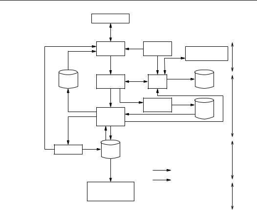
§13.7 Key life cycle issues |
|
|
|
|
|
|
579 |
|
user registration |
|
|
|
|
|
|
|
|
|
|
|
|
|
KEY STATE |
|
user |
new user |
key |
|
key establishment |
||
|
initialization |
|
|
generation |
|
||
|
|
|
|
|
|
protocol |
pre- |
|
|
|
existing user |
|
|
operational |
|
recovered key |
initial key |
|
|
|
|||
|
|
|
|
|
|||
key |
key |
|
new key |
key |
new key |
key |
|
|
|
|
|||||
recovery |
installation |
|
|
update |
|
backup |
|
key loss |
|
|
|
key |
|
public |
|
without |
|
|
|
registration |
|
operational |
|
compromise |
|
|
|
|
key |
|
|
normal use |
|
|
|
|
|
||
|
|
|
|
|
directory |
|
|
key |
of key |
|
|
|
|
|
|
compromise |
|
|
cryptoperiod expiry |
|
|
|
|
or early |
|
|
|
|
|
|
|
termination |
old key (expired) |
|
|
|
|
||
revocation |
archival |
|
|
|
|
|
|
|
|
|
|
|
|
|
post- |
|
|
|
|
|
|
|
operational |
|
|
|
|
|
key movement |
|
|
|
|
|
|
|
system trigger |
|
|
key de-registration |
|
|
|
|
|||
|
and |
|
|
|
|
|
|
|
destruction |
|
|
|
|
|
obsolete |
Figure 13.10: Key management life cycle.
2.user initialization – an entity initializes its cryptographic application (e.g., installs and initializes software or hardware), involving use or installation (see below) of initial keying material obtained during user registration.
3.key generation – generation of cryptographic keys should include measures to ensure appropriate properties for the intended application or algorithm and randomness in the sense of being predictable (to adversaries) with negligible probability (see Chapter 5). An entity may generate its own keys, or acquire keys from a trusted system component.
4.key installation – keying material is installed for operational use within an entity’s software or hardware, by a variety of techniques including one or more of the following: manual entry of a password or PIN, transfer of a disk, read-only-memory device, chipcard or other hardware token or device (e.g., key-loader). The initial keying material may serve to establish a secure on-line session through which working keys are established. During subsequent updates, new keying material is installed to replace that in use, ideally through a secure on-line update technique.
5.key registration – in association with key installation, keying material may be officially recorded (by a registration authority) as associated with a unique name which distinguishes an entity. For public keys, public-key certificates may be created by a certification authority (which serves as guarantor of this association), and made available to others through a public directory or other means (see §13.4).
580 |
Ch. 13 Key Management Techniques |
6.normal use – the objective of the life cycle is to facilitate operational availability of keying material for standard cryptographic purposes (cf. §13.5 regarding control of keys during usage). Under normal circumstances, this state continues until cryptoperiod expiry; it may also be subdivided – e.g., for encryption public-key pairs, a point may exist at which the public key is no longer deemed valid for encryption, but the private key remains in (normal) use for decryption.
7.key backup – backup of keying material in independent, secure storage media provides a data source for key recovery (point 11 below). Backup refers to short-term storage during operational use.
8.key update – prior to cryptoperiod expiry, operational keying material is replaced by new material. This may involve some combination of key generation, key derivation (§13.5.2), execution of two-party key establishment protocols (Chapter 12), or communications with a trusted third party. For public keys, update and registration of new keys typically involves secure communications protocols with certification authorities.
9.archival – keying material no longer in normal use may be archived to provide a source for key retrieval under special circumstances (e.g., settling disputes involving repudiation). Archival refers to off-line long-term storage of post-operational keys.
10.key de-registration and destruction – once there are no further requirements for the value of a key or maintaining its association with an entity, the key is de-registered (removed from all official records of existing keys), and all copies of the key are destroyed. In the case of secret keys, all traces are securely erased.
11.key recovery – if keying material is lost in a manner free of compromise (e.g., due to equipment failure or forgotten passwords), it may be possible to restore the material from a secure backup copy.
12.key revocation – it may be necessary to remove keys from operational use prior to their originally scheduled expiry, for reasons including key compromise. For public keys distributed by certificates, this involves revoking certificates (see §13.6.3).
Of the above stages, all are regularly scheduled, except key recovery and key revocation which arise under special situations.
13.45Remark (public-key vs. symmetric-key life cycle) The life cycle depicted in Figure 13.10 applies mainly to public-key pairs, and involves keying material of only a single party. The life cycle of symmetric keys (including key-encrypting and session keys) is generally less complex; for example, session keys are typically not registered, backed up, revoked, or archived.
Key states within life cycle
The typical events involving keying material over the lifetime of the key define stages of the life cycle. These may be grouped to define a smaller set of states for cryptographic keys, related to their availability for use. One classification of key states is as follows (cf. Figure 13.10):
1.pre-operational. The key is not yet available for normal cryptographic operations.
2.operational. The key is available, and in normal use.
3.post-operational. The key is no longer in normal use, but off-line access to it is possible for special purposes.
4.obsolete. The key is no longer available. All records of the key value are deleted.

§13.8 Advanced trusted third party services |
581 |
System initialization and key installation
Key management systems require an initial keying relationship to provide an initial secure channel and optionally support the establishment of subsequent working keys (long-term and short-term) by automated techniques. The initialization process typically involves noncryptographic one-time procedures such as transfer of keying material in person, by trusted courier, or over other trusted channels.
The security of a properly architected system is reduced to the security of keying material, and ultimately to the security of initial key installation. For this reason, initial key installation may involve dual or split control, requiring co-operation of two or more independent trustworthy parties (cf. Note §13.8).
13.8 Advanced trusted third party services
This section provides further details on trusted third party services of a more advanced nature, introduced briefly in §13.2.4.
13.8.1 Trusted timestamping service
A trusted timestamping service provides a user with a dated receipt (upon presentation of a document), which thereafter can be verified by others to confirm the presentation or existence of the document at the (earlier) date of receipt. Specific applications include establishing the time of existence of documents such as signed contracts or lab notes related to patent claims, or to support non-repudiation of digital signatures (§13.8.2).
The basic idea is as follows. A trusted third party T (the timestamp agent) appends a timestamp t1 to a submitted digital document or data file D, signs the composite document (thereby vouching for the time of its existence), and returns the signed document including t1 to the submitter. Subsequent verification of T ’s signature then establishes, based on trust in T , the existence of the document at the time t1.
If the data submitted for timestamping is the hash of a document, then the document content itself need not be disclosed at the time of timestamping. This also provides privacy protection from eavesdroppers in the case of submissions over an unsecured channel, and reduces bandwidth and storage costs for large documents.
13.46Remark (non-cryptographic timestamp service) A similar service may be provided by non-cryptographic techniques as follows. T stores D along with a timestamp t1, and is trusted to maintain the integrity of this record by procedural techniques. Later some party A submits the document again (now D ), and T compares D to D on file. If these match, T declares that D existed at the time t1 of the retrieved timestamp.
The timestamp agent T is trusted not to disclose its signing key, and also to competently create proper signatures. An additional desirable feature is prevention of collusion: T should be unable to successfully collude (with any party) to undetectably back-date a document. This may be ensured using Mechanism 13.47, which combines digital signatures with tree authentication based on hashing.

582 |
Ch. 13 Key Management Techniques |
13.47Mechanism Trusted timestamping service based on tree authentication
SUMMARY: party A interacts with a trusted timestamping agent T . RESULT: A obtains a timestamp on a digital document D.
1.A submits the hash value h(D) to T . (h is a collision-resistant hash function.)
2.T notes the date and time t1 of receipt, digitally signs the concatenation of h(D) and t1, and returns t1 and the signature to A. (The signature is called the certified timestamp.) A may verify the signature to confirm T ’s competence.
3.At the end of each fixed period (e.g., one day), or more frequently if there is a large number n of certified timestamps, T :
(i)computes from these an authentication tree T with root label R (see §13.4.1);
(ii)returns to A the authentication path values to its certified timestamp; and
(iii)makes the root value R widely available through a means allowing both verifiable authenticity and establishment of the time of creation tc of T (e.g., publishing in a trusted dated medium such as a newspaper).
4.To allow any other party B to verify (with T ’s verification public key) that D was submitted at time t1, A produces the certified timestamp. If trust in T itself is challenged (with respect to backdating t1), A provides the authentication path values from its certified timestamp to the root R, which B may verify (see §13.4.1) against an independently obtained authentic root value R for the period tc.
To guarantee verifiability, A should itself verify the authentication path upon receiving the path values in step 3.
13.8.2 Non-repudiation and notarization of digital signatures
The timestamping service of §13.8.1 is a document certification or document notarization service. A notary service is a more general service capable not only of ascertaining the existence of a document at a certain time, but of vouching for the truth of more general statements at specified points in time. The terminology originates from the dictionary definition of a notary public – a public official (usually a solicitor) legally authorized to administer oaths, and attest and certify certain documents. No specific legal connotation is intended in the cryptographic use of this term.
The non-repudiation aspect of digital signatures is a primary advantage of public-key cryptography. By this property, a signer is prevented from signing a document and subsequently being able to successfully deny having done so. A non-repudiation service requires specification of precise details including an adjudication process and adjudicator (judge), what evidence would be submitted to the adjudicator, and what precise process the adjudicator is to follow to render judgement on disputes. The role of an adjudicator is distinct from that of a timestamp agent or notary which generates evidence.
13.48Remark (origin authentication vs. non-repudiable signature) A fundamental distinction exists between a party A being able to convince itself of the validity of a digital signature s at a point in time t0, and that party being able to convince others at some time t1 ≥ t0 that s was valid at time t0. The former resembles data origin authentication as typically provided by symmetric-key origin authentication mechanisms, and may be accepted by a verifier as a form of authorization in an environment of mutual trust. This differs from digital signatures which are non-repudiable in the future.


584 |
Ch. 13 Key Management Techniques |
13.8.3 Key escrow
The objective of a key escrow encryption system is to provide encryption of user traffic (e.g., voice or data) such that the session keys used for traffic encryption are available to properly authorized third parties under special circumstances (“emergency access”). This grants third parties which have monitored user traffic the capability to decrypt such traffic. Wide-scale public interest in such systems arose when law enforcement agencies promoted their use to facilitate legal wiretapping of telephone calls to combat criminal activities. However, other uses in industry include recovery of encrypted data following loss of keying material by a legitimate party, or destruction of keying material due to equipment failure or malicious activities. One example of a key escrow system is given below, followed by more general issues.
(i) The Clipper key escrow system
The Clipper key escrow system involves use of the Clipper chip (or a similar tamper-resist- ant hardware device – generically referred to below as an escrow chip) in conjunction with certain administrative procedures and controls. The basic idea is to deposit two key components, which jointly determine an encryption key, with two trusted third parties (escrow agents), which subsequently allow (upon proper authorization) recovery of encrypted user data.
More specifically, encryption of telecommunications between two users proceeds as follows. Each party has a telephone combined with a key escrow chip. The users negotiate or otherwise establish a session key KS which is input to the escrow chip of the party encrypting data (near end). As a function of KS and an initialization vector (IV), the chip creates by an undisclosed method a data block called a law enforcement access field (LEAF). The LEAF and IV are transmitted to the far end during call set-up of a communications session. The near end escrow chip then encrypts the user data D under KS producing EKS (D), by a U.S. government classified symmetric algorithm named SKIPJACK. The far end escrow chip decrypts the traffic only if the transmitted LEAF validates properly. Such verification requires that this far end chip has access to a common family key KF (see below) with the near end chip.
The LEAF (see Figure 13.11) contains a copy of the session key encrypted under a device-specific key KU . KU is generated and data-filled into the chip at the time of chip manufacture, but prior to the chip being embedded in a security product. The system meets its objective by providing third party access under proper authorization (as defined by the Key Escrow System) to the device key KU of targeted individuals.
To derive the key KU embedded in an escrow chip with identifier UID, two key components (KC1, KC2) are created whose XOR is KU . Each component is encrypted under a key KCK = KN1 KN2, where KNi is input to the chip programming facility by the first and second trusted key escrow agent, respectively. (Used to program a number of chips, KNi is stored by the escrow agent for subsequent recovery of KCK.) One encrypted key component is then given to each escrow agent, which stores it along with UID to service later requests. Stored data from both agents must subsequently be obtained by an authorized official to allow recovery of KU (by recovering first KCK, and then KC1, KC2, and
KU = KC1 KC2).
Disclosed details of the LEAF are given in Figure 13.11. Each escrow chip contains a 32-bit device unique identifier (UID), an 80-bit device unique key (KU ), and an 80-bit family key (KF ) common to a larger collection of devices. The LEAF contains a copy of the 80-bit session key KS encrypted under KU , the UID, and a 16-bit encryption authentica-

§13.8 Advanced trusted third party services |
585 |
tor (EA) created by an undisclosed method; these are then encrypted under KF . Recovery of KS from the LEAF thus requires both KF and KU . The encryption authenticator is a checksum designed to allow detection of LEAF tampering (e.g., by an adversary attempting to prevent authorized recovery of KS and thereby D).
session key KS
|
|
|
|
|
|
|
|
user data D |
|
|
input from escrow agents |
|
|
Escrow chip |
|
IV |
|
||||
Chip |
|
|
|
|
|
|
|
|
|
|
|
|
|
UID |
|
|
|
|
|
|
|
|
Programming |
|
|
|
|
|
|
|
||
|
|
|
|
|
|
|
|
|
||
|
Facility |
|
|
|
|
|
|
|
|
|
output |
|
|
|
KU |
|
E |
|
|
|
|
to |
|
|
|
|
|
|
|
|
|
|
escrow |
|
KFC1 |
|
80 |
|
|
32 |
16 |
|
|
agents |
family |
KFC2 |
|
|
|
|
|
|||
|
|
|
|
|
|
|
|
|||
|
keys |
|
|
EKU |
(KS) |
UID |
EA |
|
|
|
|
|
|
|
|
|
|||||
recovery request |
|
|
|
|
|
|
|
|
E |
|
|
|
|
|
KF |
|
|
E |
|
|
|
|
|
KF |
|
|
|
|
|
|
|
|
Escrow Agent 1 |
UID |
|
wiretap |
|
|
|
|
|
|
to |
|
−1 |
EK |
(KS) |
UID |
EA |
EK (D) |
far |
|||
Escrow Agent 2 |
E |
|
processing |
U |
|
|
|
S |
end |
|
|
|
|
|
|
|
LEAF |
|
ciphertext |
||
|
|
|
|
|
|
|
|
|
||
|
recover |
|
|
|
|
|
|
|
|
|
components of escrowed KU |
KU |
KU |
|
|
KS |
|
|
D |
|
|
|
|
|
|
|
|
|
|
|
to third party |
|
Key Escrow Decrypt Processor
Schematic representation:
Escrow component |
User component |
UID = device unique identifier
KU = device unique key
KF = family key
KFC = family key component
EA = encryption authenticator
Recovery component
Figure 13.11: Creation and use of LEAF for key escrow data recovery.
(ii) Issues related to key escrow
Key escrow encryption systems may serve a wide variety of applications, and a corresponding range of features exists. Distinguishing properties of escrow systems include:
1.applicability to store-and-forward vs. real-time user communications
2.capability of real-time decryption of user traffic
3.requirement of tamper-resistant hardware or hardware with trusted clock
4.capability of user selection of escrow agents
586 |
Ch. 13 Key Management Techniques |
5.user input into value of escrowed key
6.varying trust requirements in escrow agents
7.extent of user data uncovered by one escrow access (e.g., limited to one session or fixed time period) and implications thereof (e.g., hardware replacement necessary).
Threshold systems and shared control systems may be put in place to access escrowed keying information, to limit the chances of unauthorized data recovery. Key escrow systems may be combined with other life cycle functions including key establishment, and key backup and archival (cf. key access servers – Notes 13.5 and 13.6).
13.9 Notes and further references
§13.1
Davies and Price [308] provide a comprehensive treatment of key management, including overviews of ISO 8732 [578] and techniques introduced in several 1978 IBM Systems Journal papers [364, 804]. Early work addressing protection in communications networks and/or key management includes that of Feistel, Notz, and Smith [388], Branstad [189], Kent [665], Needham and Schroeder [923], and the surveys of Popek and Kline [998] and Voydock and Kent [1225]. Security issues in electronic funds transfer (EFT) systems for point-of-sale (POS) terminals differ from those for remote banking machines due to the weaker physical security of the former; special key management techniques such as unique (derived) transaction keys reduce the implications of terminal key compromise – see Beker and Walker [85], Davies [305], and Davies and Price [308, Ch.10]. See Meyer and Matyas [859] for general symmetric-key techniques, EFT applications, and PIN management; and Ford [414] for directory services and standards, including the X.500 Directory and X.509 Authentication Framework [626].
For an overview of key management concepts and life cycles aspects, see Fumy and Landrock [429]. Fumy and Leclerc [430] consider placement of key distribution protocols within the ISO Open Systems Interconnection (OSI) architecture. Regarding key management principles, see Abadi and Needham [1], and Anderson and Needham [31]. See Vedder [1220] for security issues and architectures relevant to wireless communications, including European digital cellular (Global System for Mobile Communications – GSM) and the Digital European Cordless Telephone (DECT) system. Regarding key management for security (authentication and encryption) in North American digital cellular systems, see IS-54 Rev B [365]. ISO 11166-1 [586] (see also comments by Rueppel [1082]) specifies key management techniques and life cycle principles for use in banking systems, and is used by the Society for Worldwide Interbank Financial Telecommunications (SWIFT).
§13.2
Various parts of ISO/IEC 11770 [616, 617, 618] contain background material on key management; Figure 13.3 is derived from an early draft of 11770-3. KDCs and KTCs were popularized by ANSI X9.17 [37]. Related to tradeoffs, Needham and Schroeder [923] compare symmetric and public-key techniques; the formalization proposed by Rueppel [1080] allows analysis of security architectures to distinguish complexity-increasing from complexity-reducing techniques.
The Kerberos authentication service (§12.3.2) includes a ticket-granting service whereby a client may re-authenticate itself multiple times using its long-term secret only once. The client A first acquires a ticket-granting-ticket through a protocol with an Authentication Server (AS). Thereafter, using a variation of Protocol 12.24, A may obtain authentication
§13.9 Notes and further references |
587 |
credentials for a server B from a Ticket-Granting-Server (TGS), extracting a TGS session key from the time-limited ticket to secure protocol messages with the TGS. A’s long-term secret (password) need neither be cached for an extended period in memory nor re-entered, reducing the threat of its compromise; compromise of a TGS session key has time-restricted impact. See RFC 1510 [1041] for details.
Ford and Wiener [417] describe key access servers (Note 13.6), effectively an access control mechanism where the resource is a key package. Girault [459] mentions the three levels of trust of Remark 13.7. Digital envelopes (Note 13.6) are discussed in PKCS #7 [1072].
§13.3
Example 13.9 is from Tuchman [1198]. Davis and Swick [310] discuss symmetric-key certificates as defined herein under the name private-key certificates (crediting Abadi, Burrows, and Lampson) and propose protocols for their use with trusted third parties, including a password-based initial registration protocol. Predating this, Davies and Price [308, p.259] note that tamper-resistant hardware may replace the trusted third party requirement of symmetric-key certificates (Note 13.14). A generalization of Protocol 13.12 appears as Mechanism 11 of ISO/IEC 11770-2 [617], along with related KTC protocols offering additional authenticity guarantees (cf. Note 13.13(iii)); these provide KTC variations of the KDC protocols of §12.3.2).
§13.4
Diffie and Hellman [345] suggested using a trusted public file, maintained by a trusted authority with which each communicant registers once (in person), and from which authentic public keys of other users can be obtained. To secure requests by one party for the public key of another, Rivest, Shamir, and Adleman [1060] and Needham and Schroeder [923] note the trusted authority may respond via signed messages (essentially providing on-line certificates).
Authentication trees were first discussed in Merkle’s thesis [851, p.126-131] (see also [852, 853]). For security requirements on hash functions used for tree authentication, see Preneel [1003, p.38]. Public-key certificates were first proposed in the 1978 B.Sc. thesis of Kohnfelder [703]; the overall thesis considers implementation and systems issues related to using RSA in practice. Kohnfelder’s original certificate was an ordered triple containing a party’s name, public-key information, and an authenticator, with the authenticator a signature over the value resulting from encrypting the name with the public key/algorithm in question.
X.509 certificates [626] were defined in 1988 and modified in 1993 (yielding Version 2 certificates); an extensions field was added by a technical corrigendum [627] in 1995 (yielding Version 3 certificates). Standard extensions for Version 3 certificates appear in an amendment to X.509 [628]; these accommodate information related to key identifiers, key usage, certificate policy, alternate names (vs. X.500 names) and name attributes, certification path constraints, and enhancements for certificate revocation including revocation reasons and CRL partitioning. For details, see Ford [416]. ANSI X9.45 [49] addresses attribute certificates. The alternative of including hard-coded attribute fields within public-key certificates is proposed in PKCS #6 [1072]; suggested attributes are listed in PKCS #9 [1072].
In 1984 Shamir [1115] formulated the general idea of asymmetric systems employing user’s identities in place of public keys (identity-based systems), giving a concrete proposal for an ID-based signature system, and the model for an ID-based encryption scheme. Fiat and Shamir [395] combined this idea with that of zero-knowledge interactive proofs, yielding interactive identification and signature protocols. T. Okamoto [947] (based on a January 1984 paper in Japanese by Okamoto, Shiraishi, and Kawaoka [954]) independently proposed a specific entity-authentication scheme wherein a trusted center T distributes to a
588 |
Ch. 13 Key Management Techniques |
claimant A a secret accreditation value computed as a function of T ’s private key and A’s identity (or unique index value). The identity-based key-agreement scheme of Maurer and Yacobi [824] (cf. §12.6 notes on page 538) is an exception to Remark 13.27: extra public data DA is avoided, as ideally desired.
Gunther¨ [530] proposed a protocol for key agreement (Protocol 12.62) wherein users’ private keys are constructed by a trusted authority T based on their identities, with corresponding Diffie-Hellman public keys reconstructed from public data provided by T (herein called implicitly-certified public keys, identity-based subclass). The protocol introduced by Girault [459], based on the key agreement protocol of Paill`es and Girault [962] (itself updated by Girault and Paill`es [461] and Girault [458]) similar to a protocol of Tanaka and E. Okamoto [1184], involved what he christened self-certified public keys (herein called implicitly-certified public keys, self-certified subclass); see Mechanism 12.61.
Related to self-certified public keys, Brands [185] has proposed secret-key certificates for use in so-called restrictive blind signature schemes. These involve a data triple consisting of a private key, matching public key, and an explicit (secret-key) certificate created by a trusted third party to certify the public key. Users can themselves create pairs of public keys and matching (secret-key) certificates, but cannot create valid triples. As with self-certified keys, performance of a cryptographic action relative to the public key (e.g., signing) implicitly demonstrates that the performing party knows the private key and hence that the corresponding public key was indeed issued by the trusted third party.
§13.5
Key tags are due to Jones [642]. Key separation as in Example 13.33 is based on Ehrsam et al. [364], which outlines the use of master keys, key variants, keyand data-encrypting keys. Smid [1153] introduced key notarization in the Key Notarization System (KNS), a key management system designed by the U.S. National Bureau of Standards (now NIST), and based on a Key Notarization Facility (KNF) – a KTC-like system component trusted to handle master keys, and to generate and notarize symmetric keys. Key notarization with key offsetting (Example 13.34) is from ISO 8732 [578], which is derived from ANSI X9.17 [37].
The generalization of key notarization to control vectors is due to Matyas, Meyer, and Brachtl [806], and described by Matyas [803] (also [802]), including an efficient method for allowing arbitrary length control vectors that does not penalize short vectors. The IBM proposal specifies E as two-key triple-DES, as per ANSI X9.17. Matyas notes that a second approach to implement control vectors, using a MAC computed on the control vector and the key (albeit requiring additional processing), has the property that both the control vector and the recovered key may be authenticated before the key is used. The notion of a capability (Note 13.35) was introduced in 1966 by Dennis and Van Horn [332], who also considered the access matrix model.
§13.6
Key distribution between domains is discussed in ISO/IEC 11770-1 [616]; see also Kohl and Neuman [1041] with respect to Kerberos V5, and Davis and Swick [310]. A Kerberos domain is called a realm; authentication of clients in one realm to servers in others is supported in V5 by inter-realm keys, with a concept of authentication paths analogous to publickey certification paths.
Kent [666] overviews the design and implementation of Privacy Enhanced Mail (PEM) (see RFC 1421-1424 [1036, 1037, 1038, 1039]), a prototyped method for adding security to Internet mail. Encryption and signature capabilities are provided. The PEM infrastructure of
§13.9 Notes and further references |
589 |
RFC 1422 is based on a strict hierarchy of certification authorities, and includes specification of Policy Certification Authorities (PCAs) which define policies with respect to which certificates are issued. Regarding certification paths, see Tarah and Huitema [1185].
The 1988 version of X.509 [626] defines forward and reverse certificates, certificate chains, and cross-certificate pairs, allowing support for the general digraph trust model. The formal analysis of Gaarder and Snekkenes [433] highlights a practical difficulty in verifying the validity of certificates – the requirement of trusted timeclocks. For reports on implementations based on X.509 certificates, see Tardo and Alagappan [1186] and others [660, 72, 839]. Techniques for segmenting CRLs (Note 13.44) are included in the above-cited work on Version 3 certificate extensions [628]. Kohnfelder [703] noted many of the issues regarding certificate revocation in 1978 when use of certificates was first proposed, and suggested techniques to address revocation including manual notification, maintaining a public file identifying revoked keys, and use of certificate expiration dates (cf. Denning [326, p.170]).
§13.7
Matyas and Meyer [804] consider several life cycle aspects. ISO 11770-1 [616] provides a general overview of key management issues including key life cycle. ANSI X9.57 [52] provides broad discussion on certificate management, including trust models, registration, certificate chains, and life cycle aspects. ISO 10202-7 [584] specifies a key management life cycle for chipcards.
§13.8
Davies and Price [308] discuss practical issues related to registries of public keys, nonrepudiation, and revocation, including the use of timestamps and notarization; see also the original works of Kohnfelder [703] and Merkle [851], which include discussion of notaries. Haber and Stornetta [535] propose two additional techniques for timestamping digital data (one enhanced by Bayer, Haber, and Stornetta [79]), although tree authentication, due to Merkle [852], appears to be preferable in practice. Benaloh and de Mare [111] introduce one-way accumulators to address the same problem.
Although key backup/archive functionality existed in earlier commercial products, the widespread study of key escrow systems began circa 1992, and combines issues related to secret sharing, key establishment, and key life cycle. For practical aspects including commercial key recovery and backup, see Walker et al. [1229] and Maher [780]. Denning and Branstad [329] provide an excellent overview of the numerous proposals to date, including a taxonomy. Among such proposals and results are those of Micali [863] (see also [862]), Leighton and Micali [745], Beth et al. [125], Desmedt [338] (but see also Knudsen and Pedersen [690]), Jefferies, Mitchell, and Walker [635], Lenstra, Winkler, and Yacobi [755], Kilian and Leighton [671], Frankel and Yung [420], and Micali and Sidney [869]. In some systems, it is required that escrow agents be able to verify that (partial) keys received are authentic, raising issues of verifiable secret sharing (see Chor et al. [259]).
The Clipper chip is a tamper-resistant hardware encryption device compliant with FIPS 185 [405], a voluntary U.S. government standard intended for sensitive but unclassified phone (voice and data) communications. FIPS 185 specifies use of the SKIPJACK encryption algorithm (80-bit key, 64-bit blocks) and LEAF creation method, the details of both of which remain classified. The two initial key escrow agents named by the U.S. Government are the National Institute of Standards and Technology (NIST) and the Department of the Treasury, Automated Systems Division. Denning and Smid [331] describe the operation of an initial key escrow system employing a chip in accordance with FIPS 185. The Capstone chip, a more advanced device than Clipper, implements in addition a public key agreement algorithm, DSA, SHA, high-speed general-purpose exponentiation, and a (pure noise source)
590 |
Ch. 13 Key Management Techniques |
random number generator; it is used in the U.S. government Multilevel Information Security System Initiative (MISSI) for secure electronic mail and other applications. Blaze [152] demonstrated that a protocol attack is possible on Clipper, requiring at most 216 trial LEAF values to construct a bogus LEAF with a valid EA; Denning and Smid note this is not a threat in practical systems. For a debate on issues related to U.S. digital telephony legislation passed in October 1994 as the Communications Assistance for Law Enforcement Act (CALEA), requiring telephone companies to provide technical assistance facilitating authorized wiretapping, see Denning [328].


592 |
Ch. 14 Efficient Implementation |
very limited storage for both precomputed values and program code. For such applications, an algorithm which is less efficient in time but very efficient in memory requirements may be preferred.
The algorithms described in this chapter are those which, for the most part, have received considerable attention in the literature. Although some attempt is made to point out their relative merits, no detailed comparisons are given.
Chapter outline
§14.2 deals with the basic arithmetic operations of addition, subtraction, multiplication, squaring, and division for multiple-precision integers. §14.3 describes the basic arithmetic operations of addition, subtraction, and multiplication in Zm. Techniques described for performing modular reduction for an arbitrary modulus m are the classical method (§14.3.1), Montgomery’s method (§14.3.2), and Barrett’s method (§14.3.3). §14.3.4 describes a reduction procedure ideally suited to moduli of a special form. Greatest common divisor (gcd) algorithms are the topic of §14.4, including the binary gcd algorithm (§14.4.1) and Lehmer’s gcd algorithm (§14.4.2). Efficient algorithms for performing extended gcd computations are given in §14.4.3. Modular inverses are also considered in §14.4.3. Garner’s algorithm for implementing the Chinese remainder theorem can be found in §14.5. §14.6 is a treatment of several of the most practical exponentiation algorithms. §14.6.1 deals with exponentiation in general, without consideration of any special conditions. §14.6.2 looks at exponentiation when the base is variable and the exponent is fixed. §14.6.3 considers algorithms which take advantage of a fixed-base element and variable exponent. Techniques involving representing the exponent in non-binary form are given in §14.7; recoding the exponent may allow significant performance enhancements. §14.8 contains further notes and references.
14.2 Multiple-precision integer arithmetic
This section deals with the basic operations performed on multiple-precision integers: addition, subtraction, multiplication, squaring, and division. The algorithms presented in this section are commonly referred to as the classical methods.
14.2.1 Radix representation
Positive integers can be represented in various ways, the most common being base 10. For example, a = 123 base 10 means a = 1·102 +2·101 +3·100. For machine computations,
base 2 (binary representation) is preferable. If a = 1111011 base 2, then a = 26 + 25 + 24 + 23 + 0 · 22 + 21 + 20.
14.1Fact If b ≥ 2 is an integer, then any positive integer a can be expressed uniquely as a = anbn + an−1bn−1 + ···+ a1b+ a0, where ai is an integer with 0 ≤ ai < b for 0 ≤ i ≤ n, and an =. 0
14.2Definition The representation of a positive integer a as a sum of multiples of powers of b, as given in Fact 14.1, is called the base b or radix b representation of a.

§14.2 Multiple-precision integer arithmetic |
593 |
14.3Note (notation and terminology)
(i)The base b representation of a positive integer a given in Fact 14.1 is usually written as a = (anan−1 ···a1a0)b. The integers ai, 0 ≤ i ≤ n, are called digits. an is called the most significant digit or high-order digit; a0 the least significant digit or low-order digit. If b = 10, the standard notation is a = anan−1 ···a1a0.
(ii)It is sometimes convenient to pad high-order digits of a base b representation with 0’s; such a padded number will also be referred to as the base b representation.
(iii)If (anan−1 ···a1a0)b is the base b representation of a and an =, then0 the precision or length of ais n+1. If n = 0, then ais called a single-precision integer; otherwise, a is a multiple-precision integer. a = 0 is also a single-precision integer.
The division algorithm for integers (see Definition 2.82) provides an efficient method for determining the base b representation of a non-negative integer, for a given base b. This provides the basis for Algorithm 14.4.
14.4Algorithm Radix b representation
INPUT: integers a and b, a ≥ 0, b ≥ 2.
OUTPUT: the base b representation a = (an ···a1a0)b, where n ≥ 0 and an =if0n ≥ 1.
1.i←0, x←a, q← xb , ai←x − qb. ( · is the floor function; see page 49.)
2.While q > 0, do the following:
2.1i←i + 1, x←q, q← xb , ai←x − qb.
3.Return((aiai−1 ···a1a0)).
14.5Fact If (anan−1 ···a1a0)b is the base b representation of a and k is a positive integer,
then (ulul−1 ···u1u0)bk is the base bk representation of a, where l = (n + 1)/k − 1,
k−1 |
≤ i ≤ l − 1, and ul = |
n−lk |
alk+j bj. |
ui = j=0 aik+j bj for 0 |
j=0 |
14.6Example (radix b representation) The base 2 representation of a = 123 is (1111011)2. The base 4 representation of a is easily obtained from its base 2 representation by grouping
digits in pairs from the right: a = ((1)2(11)2(10)2(11)2)4 = (1323)4. |
|
Representing negative numbers
Negative integers can be represented in several ways. Two commonly used methods are:
1.signed-magnitude representation
2.complement representation.
These methods are described below. The algorithms provided in this chapter all assume a signed-magnitude representation for integers, with the sign digit being implicit.
(i) Signed-magnitude representation
The sign of an integer (i.e., either positive or negative) and its magnitude (i.e., absolute value) are represented separately in a signed-magnitude representation. Typically, a positive integer is assigned a sign digit 0, while a negative integer is assigned a sign digit b−1. For n-digit radix b representations, only 2bn−1 sequences out of the bn possible sequences are utilized: precisely bn−1 −1 positive integers and bn−1 −1 negative integers can be represented, and 0 has two representations. Table 14.1 illustrates the binary signed-magnitude representation of the integers in the range [7,−7].


598 |
Ch. 14 Efficient Implementation |
14.2.5 Division
Division is the most complicated and costly of the basic multiple-precision operations. Algorithm 14.20 computes the quotient q and remainder r in radix b representation when x is divided by y.
14.20Algorithm Multiple-precision division
INPUT: positive integers x = (xn ···x1x0)b, y = (yt ···y1y0)b with n ≥ t ≥ 1, yt =. 0 OUTPUT: the quotient q = (qn−t ···q1q0)b and remainder r = (rt ···r1r0)b such that
x= qy + r, 0 ≤ r < y.
1.For j from 0 to (n − t) do: qj←0.
2.While (x ≥ ybn−t) do the following: qn−t←qn−t + 1, x←x − ybn−t.
3.For i from n down to (t + 1) do the following:
3.1If xi = yt then set qi−t−1←b − 1; otherwise set qi−t−1← (xib + xi−1)/yt) .
3.2While (qi−t−1(ytb + yt−1) > xib2 + xi−1b+ xi−2) do: qi−t−1←qi−t−1 −1.
3.3x←x − qi−t−1ybi−t−1.
3.4If x < 0 then set x←x + ybi−t−1 and qi−t−1←qi−t−1 − 1.
4.r←x.
5.Return(q,r).
14.21 Example (multiple-precision division) Let x = 721948327, y = 84461, so that n = 8 and t = 4. Table 14.5 illustrates the steps in Algorithm 14.20. The last row gives the quotient
q = 8547 and the remainder r = 60160. |
|
|
|
|
|
|
|
|
|
|||||||
|
|
|
|
|
|
|
|
|
|
|
|
|
|
|
|
|
|
i |
q4 |
q3 |
q2 |
q1 |
q0 |
x8 |
x7 |
x6 |
x5 |
x4 |
x3 |
x2 |
x1 |
x0 |
|
|
|
|
|
|
|
|
|
|
|
|
|
|
|
|
|
|
|
– |
0 |
0 |
0 |
0 |
0 |
7 |
2 |
1 |
9 |
4 |
8 |
3 |
2 |
7 |
|
|
8 |
0 |
9 |
0 |
0 |
0 |
7 |
2 |
1 |
9 |
4 |
8 |
3 |
2 |
7 |
|
|
|
|
8 |
0 |
0 |
0 |
|
4 |
6 |
2 |
6 |
0 |
3 |
2 |
7 |
|
|
7 |
|
8 |
5 |
0 |
0 |
|
|
4 |
0 |
2 |
9 |
8 |
2 |
7 |
|
|
6 |
|
8 |
5 |
5 |
0 |
|
|
4 |
0 |
2 |
9 |
8 |
2 |
7 |
|
|
|
|
8 |
5 |
4 |
0 |
|
|
|
6 |
5 |
1 |
3 |
8 |
7 |
|
|
5 |
|
8 |
5 |
4 |
8 |
|
|
|
6 |
5 |
1 |
3 |
8 |
7 |
|
|
|
|
8 |
5 |
4 |
7 |
|
|
|
|
6 |
0 |
1 |
6 |
0 |
|
|
|
|
|
|
|
|
|
|
|
|
|
|
|
|
|
|
Table 14.5: Multiple-precision division (see Example 14.21).
14.22Note (comments on Algorithm 14.20)
(i)Step 2 of Algorithm 14.20 is performed at most once if yt ≥ 2b and b is even.
(ii)The condition n ≥ t ≥ 1 can be replaced by n ≥ t ≥ 0, provided one takes xj = yj = 0 whenever a subscript j < 0 in encountered in the algorithm.
14.23Note (normalization) The estimate for the quotient digit qi−t−1 in step 3.1 of Algorithm
14.20 is never less than the true value of the quotient digit. Furthermore, if yt ≥ 2b , then step 3.2 is repeated no more than twice. If step 3.1 is modified so that qi−t−1← (xib2 + xi−1b + xi−2)/(ytb + yt−1) , then the estimate is almost always correct and step 3.2 is

§14.3 Multiple-precision modular arithmetic |
599 |
never repeated more than once. One can always guarantee that yt ≥ 2b by replacing the integers x, y by λx, λy for some suitable choice of λ. The quotient of λx divided by λy is the same as that of x by y; the remainder is λ times the remainder of x divided by y. If the base bis a power of 2 (as in many applications), then the choice of λshould be a power of 2; multiplication by λ is achieved by simply left-shifting the binary representations of x and y. Multiplying by a suitable choice of λ to ensure that yt ≥ 2b is called normalization. Example 14.24 illustrates the procedure.
14.24 Example (normalized division) Take x = 73418 and y = 267. Normalize x and y by multiplying each by λ = 3: x = 3x = 220254 and y = 3y = 801. Table 14.6 shows the steps of Algorithm 14.20 as applied to x and y . When x is divided by y , the quotient is 274, and the remainder is 780. When x is divided by y, the quotient is also 274 and the
remainder is 780/3 = 260. |
|
|
|
|
|
|
|
|
|
|
|
||
|
|
|
|
|
|
|
|
|
|
|
|
|
|
|
i |
q3 |
q2 |
q1 |
q0 |
|
x5 |
x4 |
x3 |
x2 |
x1 |
x0 |
|
|
|
|
|
|
|
|
|
|
|
|
|
|
|
|
− |
0 |
0 |
0 |
0 |
|
2 |
2 |
0 |
2 |
5 |
4 |
|
|
5 |
0 |
2 |
0 |
0 |
|
|
6 |
0 |
0 |
5 |
4 |
|
|
4 |
|
2 |
7 |
0 |
|
|
|
3 |
9 |
8 |
4 |
|
|
3 |
|
2 |
7 |
4 |
|
|
|
|
7 |
8 |
0 |
|
Table 14.6: Multiple-precision division after normalization (see Example 14.24).
14.25Note (computational efficiency of Algorithm 14.20 with normalization)
(i)(multiplication count) Assuming that normalization extends the number of digits in x by 1, each iteration of step 3 requires 1 + (t + 2) = t + 3 single-precision multiplications. Hence, Algorithm 14.20 with normalization requires about (n−t)(t+ 3) single-precision multiplications.
(ii)(division count) Since step 3.1 of Algorithm 14.20 is executed n − t times, at most n − t single-precision divisions are required when normalization is used.
14.3Multiple-precision modular arithmetic
§14.2 provided methods for carrying out the basic operations (addition, subtraction, multiplication, squaring, and division) with multiple-precision integers. This section deals with these operations in Zm, the integers modulo m, where m is a multiple-precision positive integer. (See §2.4.3 for definitions of Zm and related operations.)
Let m = (mnmn−1 ···m1m0)b be a positive integer in radix b representation. Let x = (xnxn−1 ···x1x0)b and y = (ynyn−1 ···y1y0)b be non-negative integers in base b representation such that x < m and y < m. Methods described in this section are for computing x + y mod m (modular addition), x − y mod m (modular subtraction), and x·y mod m (modular multiplication). Computing x−1 mod m (modular inversion) is addressed in §14.4.3.
14.26Definition If z is any integer, then z mod m (the integer remainder in the range [0,m−1] after z is divided by m) is called the modular reduction of z with respect to modulus m.

600 |
Ch. 14 Efficient Implementation |
Modular addition and subtraction
As is the case for ordinary multiple-precision operations, addition and subtraction are the simplest to compute of the modular operations.
14.27Fact Let x and y be non-negative integers with x,y < m. Then:
(i)x + y < 2m;
(ii)if x ≥ y, then 0 ≤ x − y < m; and
(iii)if x < y, then 0 ≤ x + m − y < m.
If x,y Zm, then modular addition can be performed by using Algorithm 14.7 to add xand y as multiple-precision integers, with the additional step of subtracting mif (and only if) x + y ≥ m. Modular subtraction is precisely Algorithm 14.9, provided x ≥ y.
14.3.1 Classical modular multiplication
Modular multiplication is more involved than multiple-precision multiplication (§14.2.3), requiring both multiple-precision multiplication and some method for performing modular reduction (Definition 14.26). The most straightforward method for performing modular reduction is to compute the remainder on division by m, using a multiple-precision division algorithm such as Algorithm 14.20; this is commonly referred to as the classical algorithm for performing modular multiplication.
14.28Algorithm Classical modular multiplication
INPUT: two positive integers x, y and a modulus m, all in radix b representation. OUTPUT: x ·y mod m.
1.Compute x · y (using Algorithm 14.12).
2.Compute the remainder r when x · y is divided by m (using Algorithm 14.20).
3.Return(r).
14.3.2 Montgomery reduction
Montgomery reduction is a technique which allows efficient implementation of modular multiplication without explicitly carrying out the classical modular reduction step.
Let mbe a positive integer, and let Rand T be integers such that R > m,gcd(m,R) = 1, and 0 ≤ T < mR. A method is described for computing TR−1 mod m without using the classical method of Algorithm 14.28. TR−1 mod m is called a Montgomery reduction of T modulo m with respect to R. With a suitable choice of R, a Montgomery reduction can be efficiently computed.
Suppose x and y are integers such that 0 ≤ x,y < m. Let x = xR mod m and y = yR mod m. The Montgomery reduction of xy is xyR−1 mod m = xyR mod m. This observation is used in Algorithm 14.94 to provide an efficient method for modular exponentiation.
To briefly illustrate, consider computing x5 mod m for some integer x,1 ≤ x < m. First compute x = xR mod m. Then compute the Montgomery reduction of xx, which is A = x2R−1 mod m. The Montgomery reduction of A2 is A2R−1 mod m = x4R−3 mod m. Finally, the Montgomery reduction of (A2R−1 mod m)xis (A2R−1)xR−1 mod m = x5R−4 mod m = x5R mod m. Multiplying this value by R−1 mod m and reducing

§14.3 Multiple-precision modular arithmetic |
601 |
modulo m gives x5 mod m. Provided that Montgomery reductions are more efficient to compute than classical modular reductions, this method may be more efficient than computing x5 mod m by repeated application of Algorithm 14.28.
If mis represented as a base binteger of length n, then a typical choice for R is bn. The condition R > m is clearly satisfied, but gcd(R,m) = 1 will hold only if gcd(b,m) = 1. Thus, this choice of R is not possible for all moduli. For those moduli of practical interest (such as RSA moduli), m will be odd; then b can be a power of 2 and R = bn will suffice.
Fact 14.29 is basic to the Montgomery reduction method. Note 14.30 then implies that
R= bn is sufficient (but not necessary) for efficient implementation.
14.29Fact (Montgomery reduction) Given integers m and R where gcd(m,R) = 1, let m = −m−1 mod R, and let T be any integer such that 0 ≤ T < mR. If U = Tm mod R, then (T + Um)/R is an integer and (T + Um)/R ≡ TR−1 (mod m).
Justification. T + Um ≡ T (mod m) and, hence, (T + Um)R−1 ≡ TR−1 (mod m). To see that (T + Um)R−1 is an integer, observe that U = Tm + kR and m m = −1 + lR for some integers k and l. It follows that (T + Um)/R = (T + (Tm + kR)m)/R = (T + T(−1 + lR) + kRm)/R = lT + km.
14.30Note (implications of Fact 14.29)
(i)(T + Um)/R is an estimate for TR−1 mod m. Since T < mR and U < R, then
(T +Um)/R < (mR+mR)/R = 2m. Thus either (T +Um)/R = TR−1 mod m or (T+Um)/R = (TR−1 mod m)+m(i.e., the estimate is within mof the residue). Example 14.31 illustrates that both possibilities can occur.
(ii)If all integers are represented in radix b and R = bn, then TR−1 mod m can be computed with two multiple-precision multiplications (i.e., U = T · m and U · m) and simple right-shifts of T + Um in order to divide by R.
14.31Example (Montgomery reduction) Let m = 187,R = 190. Then R−1 mod m = 125,
m−1 mod R = 63, and m = 127. If T = 563, then U = Tm mod R = 61 and
(T + Um)/R = 63 = TR−1 mod m. If T = 1125 then U = Tm mod R = 185 and (T + Um)/R = 188 = (TR−1 mod m) + m.
Algorithm 14.32 computes the Montgomery reduction of T = (t2n−1 ···t1t0)b when R = bn and m = (mn−1 ···m1m0)b. The algorithm makes implicit use of Fact 14.29 by computing quantities which have similar properties to U = Tm mod R and T + Um, although the latter two expressions are not computed explicitly.
14.32Algorithm Montgomery reduction
INPUT: integers m = (mn−1 ···m1m0)b with gcd(m,b) = 1, R = bn, m = −m−1 mod
b, and T = (t2n−1 ···t1t0)b < mR. OUTPUT: TR−1 mod m.
1.A←T. (Notation: A = (a2n−1 ···a1a0)b.)
2.For i from 0 to (n − 1) do the following:
2.1ui←aim mod b.
2.2A←A + uimbi.
3.A←A/bn.
4.If A ≥ m then A←A − m.
5.Return(A).

602 Ch. 14 Efficient Implementation
14.33 Note (comments on Montgomery reduction) |
|
|
|
|
|
|
|
|||
(i) |
Algorithm 14.32 does not require m = −m−1 mod R, as Fact 14.29 does, but rather |
|||||||||
|
m = −m−1 mod b. This is due to the choice of R = bn. |
|
|
|
||||||
(ii) |
At step 2.1 of the algorithm with i = l, A has the property that aj = 0,0 ≤ j ≤ l−1. |
|||||||||
|
Step 2.2 does not modify these values, but does replace al by 0. It follows that in |
|||||||||
|
step 3, A is divisible by bn. |
|
|
|
|
|
|
|
||
(iii) |
Going into step 3, the value of A equals T plus some multiple of m (see step 2.2); |
|||||||||
|
here A = (T + km)/bn is an integer (see (ii) above) and A ≡ TR−1 (mod m). It |
|||||||||
|
remains to show that A is less than 2m, so that at step 4, a subtraction (rather than a |
|||||||||
|
division) will suffice. Going into step 3, A |
= |
T |
n−1 u |
bim. But |
n−1 u |
bim < |
|||
|
b |
n |
|
|
+ i=0 |
i |
|
i=0 i |
|
|
|
|
m = Rm and T < Rm; hence, A < 2Rm. Going into step 4 (after division of A |
||||||||
by R), A < 2m as required.
14.34Note (computational efficiency of Montgomery reduction) Step 2.1 and step 2.2 of Algorithm 14.32 require a total of n + 1 single-precision multiplications. Since these steps are executed n times, the total number of single-precision multiplications is n(n + 1). Algorithm 14.32 does not require any single-precision divisions.
14.35Example (Montgomery reduction) Let m = 72639, b = 10, R = 105, and T = 7118368. Here n = 5, m = −m−1 mod 10 = 1, T mod m = 72385, and TR−1 mod m = 39796.
Table 14.7 displays the iterations of step 2 in Algorithm 14.32. |
|
|||||
|
|
|
|
|
|
|
|
i |
|
ui = aim mod 10 |
uimbi |
A |
|
|
|
|
|
|
|
|
|
− |
|
− |
− |
7118368 |
|
|
0 |
|
8 |
581112 |
7699480 |
|
|
1 |
|
8 |
5811120 |
13510600 |
|
|
2 |
|
6 |
43583400 |
57094000 |
|
|
3 |
|
4 |
290556000 |
347650000 |
|
|
4 |
|
5 |
3631950000 |
3979600000 |
|
|
|
|
|
|
|
|
Table 14.7: Montgomery reduction algorithm (see Example 14.35).
Montgomery multiplication
Algorithm 14.36 combines Montgomery reduction (Algorithm 14.32) and multiple-precis- ion multiplication (Algorithm 14.12) to compute the Montgomery reduction of the product of two integers.
14.36Algorithm Montgomery multiplication
INPUT: integers m = (mn−1 ···m1m0)b, x = (xn−1 ···x1x0)b, y = (yn−1 ···y1y0)b with 0 ≤ x,y < m, R = bn with gcd(m,b) = 1, and m = −m−1 mod b.
OUTPUT: xyR−1 mod m.
1.A←0. (Notation: A = (anan−1 ···a1a0)b.)
2.For i from 0 to (n − 1) do the following:
2.1ui←(a0 + xiy0)m mod b.
2.2A←(A + xiy + uim)/b.
3.If A ≥ m then A←A − m.
4.Return(A).

§14.3 Multiple-precision modular arithmetic |
603 |
14.37Note (partial justification of Algorithm 14.36) Suppose at the ith iteration of step 2 that
0 ≤ A < 2m−1. Step 2.2 replaces A with (A+ xiy+ uim)/b; but (A+ xiy+ uim)/b ≤
(2m − 2 + (b − 1)(m − 1) + (b − 1)m)/b = 2m − 1 − (1/b). Hence, A < 2m − 1, justifying step 3.
14.38Note (computational efficiency of Algorithm 14.36) Since A+ xiy + uim is a multiple of b, only a right-shift is required to perform a division by b in step 2.2. Step 2.1 requires two single-precision multiplications and step 2.2 requires 2n. Since step 2 is executed n times, the total number of single-precision multiplications is n(2 + 2n) = 2n(n + 1).
14.39Note (computing xy mod m with Montgomery multiplication) Suppose x, y, and m are
n-digit base b integers with 0 ≤ x,y < m. Neglecting the cost of the precomputation in the input, Algorithm 14.36 computes xyR−1 mod m with 2n(n+1) single-precision multiplications. Neglecting the cost to compute R2 mod m and applying Algorithm 14.36 to xyR−1 mod m and R2 mod m, xy mod m is computed in 4n(n+ 1) single-precision operations. Using classical modular multiplication (Algorithm 14.28) would require 2n(n+1)
single-precision operations and no precomputation. Hence, the classical algorithm is superior for doing a single modular multiplication; however, Montgomery multiplication is very effective for performing modular exponentiation (Algorithm 14.94).
14.40Remark (Montgomery reduction vs. Montgomery multiplication) Algorithm 14.36 (Montgomery multiplication) takes as input two n-digit numbers and then proceeds to interleave the multiplication and reduction steps. Because of this, Algorithm 14.36 is not able to take advantage of the special case where the input integers are equal (i.e., squaring). On the other hand, Algorithm 14.32 (Montgomery reduction) assumes as input the product of two integers, each of which has at most n digits. Since Algorithm 14.32 is independent of multipleprecision multiplication, a faster squaring algorithm such as Algorithm 14.16 may be used prior to the reduction step.
14.41 Example (Montgomery multiplication) In Algorithm 14.36, let m = 72639, R = 105, x = 5792, y = 1229. Here n = 5, m = −m−1 mod 10 = 1, and xyR−1 mod m =
39796. Notice that m and R are the same values as in Example 14.35, as is xy = 7118368.
Table 14.8 displays the steps in Algorithm 14.36. |
|
|
|
|||||
|
|
|
|
|
|
|
|
|
|
i |
xi |
xiy0 |
ui |
xiy |
uim |
A |
|
|
|
|
|
|
|
|
|
|
|
0 |
2 |
18 |
8 |
2458 |
581112 |
58357 |
|
|
1 |
9 |
81 |
8 |
11061 |
581112 |
65053 |
|
|
2 |
7 |
63 |
6 |
8603 |
435834 |
50949 |
|
|
3 |
5 |
45 |
4 |
6145 |
290556 |
34765 |
|
|
4 |
0 |
0 |
5 |
0 |
363195 |
39796 |
|
Table 14.8: Montgomery multiplication (see Example 14.41).
14.3.3 Barrett reduction
Barrett reduction (Algorithm 14.42) computes r = x mod mgiven xand m. The algorithm requires the precomputation of the quantity µ = b2k/m ; it is advantageous if many reductions are performed with a single modulus. For example, each RSA encryption for one entity requires reduction modulo that entity’s public key modulus. The precomputation takes

604 |
Ch. 14 Efficient Implementation |
a fixed amount of work, which is negligible in comparison to modular exponentiation cost. Typically, the radix b is chosen to be close to the word-size of the processor. Hence, assume b > 3 in Algorithm 14.42 (see Note 14.44 (ii)).
14.42Algorithm Barrett modular reduction
INPUT: positive integers x = (x2k−1 ···x1x0)b, m = (mk−1 ···m1m0)b (with mk−1 = 0), and µ = b2k/m .
OUTPUT: r = x mod m.
1.q1← x/bk−1 , q2←q1 ·µ, q3← q2/bk+1 .
2.r1←x mod bk+1, r2←q3 · m mod bk+1, r←r1 − r2.
3.If r < 0 then r←r + bk+1.
4.While r ≥ m do: r←r − m.
5.Return(r).
14.43Fact By the division algorithm (Definition 2.82), there exist integers Q and R such that x = Qm + R and 0 ≤ R < m. In step 1 of Algorithm 14.42, the following inequality is satisfied: Q − 2 ≤ q3 ≤ Q.
14.44Note (partial justification of correctness of Barrett reduction)
(i)Algorithm 14.42 is based on the observation that x/m can be written as Q =
(x/bk−1)(b2k/m)(1/bk+1) . Moreover, Q can be approximated by the quantity q3 = x/bk−1 µ/bk+1 . Fact 14.43 guarantees that q3 is never larger than the true quotient Q, and is at most 2 smaller.
(ii)In step 2, observe that −bk+1 < r1 − r2 < bk+1, r1 − r2 ≡ (Q − q3)m + R (mod bk+1), and 0 ≤ (Q − q3)m + R < 3m < bk+1 since m < bk and 3 < b. If r1 −r2 ≥ 0, then r1 −r2 = (Q−q3)m+ R. If r1 −r2 < 0, then r1 −r2 + bk+1 = (Q − q3)m + R. In either case, step 4 is repeated at most twice since 0 ≤ r < 3m.
14.45Note (computational efficiency of Barrett reduction)
(i)All divisions performed in Algorithm 14.42 are simple right-shifts of the base b representation.
(ii)q2 is only used to compute q3. Since the k + 1 least significant digits of q2 are not needed to determine q3, only a partial multiple-precision multiplication (i.e., q1 · µ) is necessary. The only influence of the k + 1 least significant digits on the higher order digits is the carry from position k + 1 to position k + 2. Provided the base b
is sufficiently large with respect to k, this carry can be accurately computed by only calculating the digits at positions k and k+1. 1 Hence, the k−1 least significant digits
of q2 need not be computed. Since µ and q1 have at most k+ 1 digits, determining q3
requires at most (k + 1)2 − k2 = (k2 + 5k + 2)/2 single-precision multiplications. (iii) In step 2 of Algorithm 14.42, r2 can also be computed by a partial multiple-precision
multiplication which evaluates only the least significant k + 1 digits of q3 · m. This
can be done in at most k+1 + k single-precision multiplications.
2
14.46 Example (Barrett reduction) Let b = 4, k = 3, x = (313221)b, and m = (233)b (i.e., x = 3561 and m = 47). Then µ = 46/m = 87 = (1113)b, q1 = (313221)b/42 = (3132)b, q2 = (3132)b · (1113)b = (10231302)b, q3 = (1023)b, r1 = (3221)b, r2 = (1023)b · (233)b mod b4 = (3011)b, and r = r1 − r2 = (210)b. Thus x mod m = 36.
1If b > k, then the carry computed by simply considering the digits at position k − 1 (and ignoring the carry from position k − 2) will be in error by at most 1.

§14.3 Multiple-precision modular arithmetic |
605 |
14.3.4 Reduction methods for moduli of special form
When the modulus has a special (customized) form, reduction techniques can be employed to allow more efficient computation. Suppose that the modulus mis a t-digit base bpositive integer of the form m = bt − c, where c is an l-digit base b positive integer (for some l < t). Algorithm 14.47 computes x mod mfor any positive integer xby using only shifts, additions, and single-precision multiplications of base b numbers.
14.47Algorithm Reduction modulo m = bt − c
INPUT: a base b, positive integer x, and a modulus m = bt − c, where c is an l-digit base b integer for some l < t.
OUTPUT: r = x mod m.
1.q0← x/bt , r0←x − q0bt, r←r0, i←0.
2.While qi > 0 do the following:
2.1qi+1← qic/bt , ri+1←qic − qi+1bt.
2.2i←i + 1, r←r + ri.
3.While r ≥ m do: r←r − m.
4.Return(r).
14.48Example (reduction modulo bt − c) Let b = 4, m = 935 = (32213)4, and x = 31085 = (13211231)4. Since m = 45 − (1121)4, take c = (1121)4. Here t = 5 and l = 4. Table 14.9 displays the quotients and remainders produced by Algorithm 14.47. At the be-
ginning of step 3, r = (102031)4. Since r > m, step 3 computes r − m = (3212)4. |
|
||||||
|
|
|
|
|
|
|
|
|
i |
qi−1c |
qi |
ri |
r |
|
|
|
|
|
|
|
|
|
|
|
0 |
– |
(132)4 |
(11231)4 |
(11231)4 |
|
|
|
1 |
(221232)4 |
(2)4 |
(21232)4 |
(33123)4 |
|
|
|
2 |
(2302)4 |
(0)4 |
(2302)4 |
(102031)4 |
|
|
Table 14.9: Reduction modulo m = bt − c (see Example 14.48).
14.49Fact (termination) For some integer s ≥ 0, qs = 0; hence, Algorithm 14.47 terminates.
Justification. qic = qi+1bt +ri+1, i ≥ 0. Since c < bt, qi = (qi+1bt/c)+(ri+1/c) > qi+1. Since the qi’s are non-negative integers which strictly decrease as i increases, there is some integer s ≥ 0 such that qs = 0.
14.50Fact (correctness) Algorithm 14.47 terminates with the correct residue modulo m.
Justification. Suppose that s is the smallest index i for which qi = 0 (i.e., qs = 0). Now,
x = q0bt + r0 and qic = qi+1bt + ri+1, 0 ≤ i ≤ s − 1. Adding these equations gives |
|||
|
c = |
|
|
x + is=0−1 qi |
is=0−1 qi bt + |
is=0 ri. Since bt ≡ c (mod m), it follows that |
|
x ≡ is=0 ri |
(mod m). Hence, repeated subtraction of m from r = is=0 ri gives the |
||
correct residue.
606 |
Ch. 14 Efficient Implementation |
14.51Note (computational efficiency of reduction modulo bt − c)
(i)Suppose that x has 2t base b digits. If l ≤ t/2, then Algorithm 14.47 executes step 2 at most s = 3 times, requiring 2 multiplications by c. In general, if l is approximately (s −2)t/(s−1), then Algorithm 14.47 executes step 2 about s times. Thus, Algorithm 14.47 requires about sl single-precision multiplications.
(ii)If c has few non-zero digits, then multiplication by c will be relatively inexpensive. If c is large but has few non-zero digits, the number of iterations of Algorithm 14.47 will be greater, but each iteration requires a very simple multiplication.
14.52Note (modifications) Algorithm 14.47 can be modified if m = bt + c for some positive integer c < bt: in step 2.2, replace r←r + ri with r←r + (−1)iri.
14.53Remark (using moduli of a special form) Selecting RSA moduli of the form bt ± c for small values of c limits the choices of primes p and q. Care must also be exercised when selecting moduli of a special form, so that factoring is not made substantially easier; this is because numbers of this form are more susceptible to factoring by the special number field sieve (see §3.2.7). A similar statement can be made regarding the selection of primes of a special form for cryptographic schemes based on the discrete logarithm problem.
14.4Greatest common divisor algorithms
Many situations in cryptography require the computation of the greatest common divisor (gcd) of two positive integers (see Definition 2.86). Algorithm 2.104 describes the classical Euclidean algorithm for this computation. For multiple-precision integers, Algorithm 2.104 requires a multiple-precision division at step 1.1 which is a relatively expensive operation. This section describes three methods for computing the gcd which are more efficient than the classical approach using multiple-precision numbers. The first is non-Euclidean and is referred to as the binary gcd algorithm (§14.4.1). Although it requires more steps than the classical algorithm, the binary gcd algorithm eliminates the computationally expensive division and replaces it with elementary shifts and additions. Lehmer’s gcd algorithm (§14.4.2) is a variant of the classical algorithm more suited to multiple-precision computations. A binary version of the extended Euclidean algorithm is given in §14.4.3.
14.4.1 Binary gcd algorithm
14.54Algorithm Binary gcd algorithm
INPUT: two positive integers x and y with x ≥ y. OUTPUT: gcd(x,y).
1.g←1.
2.While both x and y are even do the following: x←x/2, y←y/2, g←2g.
3.While x =do0 the following:
3.1While x is even do: x←x/2.
3.2While y is even do: y←y/2.
3.3t←|x − y|/2.
3.4If x ≥ y then x←t; otherwise, y←t.
4.Return(g ·y).

§14.4 Greatest common divisor algorithms |
607 |
14.55 Example (binary gcd algorithm) The following table displays the steps performed by Al-
gorithm 14.54 for computing gcd(1764,868) = 28. |
|
|
|
|
|
|||||||
|
|
|
|
|
|
|
|
|
|
|
|
|
|
x |
|
1764 |
441 |
112 |
7 |
7 |
7 |
7 |
7 |
0 |
|
|
y |
|
868 |
217 |
217 |
217 |
105 |
49 |
21 |
7 |
7 |
|
|
g |
|
1 |
4 |
4 |
4 |
4 |
4 |
4 |
4 |
4 |
|
14.56Note (computational efficiency of Algorithm 14.54)
(i)If xand y are in radix 2 representation, then the divisions by 2 are simply right-shifts.
(ii)Step 3.3 for multiple-precision integers can be computed using Algorithm 14.9.
14.4.2 Lehmer’s gcd algorithm
Algorithm 14.57 is a variant of the classical Euclidean algorithm (Algorithm 2.104) and is suited to computations involving multiple-precision integers. It replaces many of the multiple-precision divisions by simpler single-precision operations.
Let x and y be positive integers in radix b representation, with x ≥ y. Without loss of generality, assume that x and y have the same number of base b digits throughout Algorithm 14.57; this may necessitate padding the high-order digits of y with 0’s.
14.57Algorithm Lehmer’s gcd algorithm
INPUT: two positive integers x and y in radix b representation, with x ≥ y. OUTPUT: gcd(x,y).
1.While y ≥ b do the following:
1.1Set x, y to be the high-order digit of x, y, respectively (y could be 0).
1.2A←1, B←0, C←0, D←1.
1.3While (y + C) =and0 (y + D) =do0 the following:
q← (x + A)/(y + C) , q ← (x + B)/(y + D) . If q =q then go to step 1.4.
t←A − qC, A←C, C←t, t←B − qD, B←D, D←t. t←x − qy, x←y, y←t.
1.4If B = 0, then T←x mod y, x←y, y←T;
otherwise, T←Ax + By, u←Cx + Dy, x←T, y←u.
2.Compute v = gcd(x,y) using Algorithm 2.104.
3.Return(v).
14.58Note (implementation notes for Algorithm 14.57)
(i)T is a multiple-precision variable. A, B, C, D, and t are signed single-precision variables; hence, one bit of each of these variables must be reserved for the sign.
(ii)The first operation of step 1.3 may result in overflow since 0 ≤ x + A,y + D ≤ b. This possibility needs to be accommodated. One solution is to reserve two bits more than the number of bits in a digit for each of x and y to accommodate both the sign and the possible overflow.
(iii)The multiple-precision additions of step 1.4 are actually subtractions, since AB ≤ 0 and CD ≤ 0.


§14.5 Chinese remainder theorem for integers |
|
|
|
|
|
|
611 |
|||||||
|
|
|
|
|
|
|
|
|
|
|
|
|
|
|
|
iteration: |
|
1 |
2 |
3 |
|
4 |
5 |
6 |
7 |
8 |
9 |
10 |
|
|
u |
|
383 |
112 |
56 |
|
28 |
14 |
7 |
7 |
7 |
7 |
7 |
|
|
v |
|
271 |
271 |
271 |
|
271 |
271 |
271 |
264 |
132 |
66 |
33 |
|
|
B |
|
0 |
−1 |
−192 |
|
−96 |
−48 |
−24 |
−24 |
−24 |
−24 |
−24 |
|
|
D |
|
1 |
1 |
1 |
|
1 |
1 |
1 |
25 |
−179 |
−281 |
−332 |
|
|
iteration: |
|
11 |
12 |
13 |
|
14 |
15 |
16 |
17 |
18 |
19 |
|
|
|
u |
|
7 |
7 |
7 |
|
7 |
4 |
2 |
1 |
1 |
1 |
|
|
|
v |
|
26 |
13 |
6 |
|
3 |
3 |
3 |
3 |
2 |
1 |
|
|
|
B |
|
−24 |
−24 |
−24 |
|
−24 |
41 |
−171 |
−277 |
−277 |
−277 |
|
|
|
D |
|
−308 |
−154 |
−130 |
|
−65 |
−65 |
−65 |
−65 |
212 |
106 |
|
|
Table 14.13: Inverse computation using the binary extended gcd algorithm (see Example 14.65).
method of choice for large integers. Garner’s algorithm (Algorithm 14.71) has some computational advantages. §14.5.1 describes an alternate (non-radix) representation for nonnegative integers, called a modular representation, that allows some computational advantages compared to standard radix representations. Algorithm 14.71 provides a technique for converting numbers from modular to base b representation.
14.5.1 Residue number systems
In previous sections, non-negative integers have been represented in radix b notation. An alternate means is to use a mixed-radix representation.
14.66 Fact Let B be a fixed positive integer. Let m1,m2,... ,mt be positive integers such that
gcd(mi,mj) = 1 for all i =j, and M = t=1 mi ≥ B. Then each integer x, 0 ≤ x < B,
i
can be uniquely represented by the sequence of integers v(x) = (v1,v2,... ,vt), where vi = x mod mi, 1 ≤ i ≤ t.
14.67Definition Referring to Fact 14.66, v(x) is called the modular representation or mixed-
radix representation of x for the moduli m1,m2,... ,mt. The set of modular representations for all integers x in the range 0 ≤ x < B is called a residue number system.
If v(x) = (v1,v2,... ,vt) and v(y) = (u1,u2,... ,ut), define v(x)+v(y) = (w1,w2,
... ,wt) where wi = vi + ui mod mi, and v(x) · v(y) = (z1,z2,... ,zt) where zi = vi · ui mod mi.
14.68Fact If 0 ≤ x,y < M, then v((x+ y) mod M) = v(x) + v(y) and v((x·y) mod M) = v(x) · v(y).
14.69Example (modular representation) Let M = 30 = 2×3×5; here, t = 3, m1 = 2, m1 = 3, and m3 = 5. Table 14.14 displays each residue modulo 30 along with its associated modular representation. As an example of Fact 14.68, note that 21 + 27 ≡ 18 (mod 30) and (101) + (102) = (003). Also 22 · 17 ≡ 14 (mod 30) and (012) ·(122) = (024).
14.70Note (computational efficiency of modular representation for RSA decryption) Suppose that n = pq, where p and q are distinct primes. Fact 14.68 implies that xd mod n can be
computed in a modular representation as vd(x); that is, if v(x) = (v1,v2) with respect to moduli m1 = p, m2 = q, then vd(x) = (v1d mod p,v2d mod q). In general, computing

612 |
|
|
|
|
|
|
|
|
|
|
Ch. 14 Efficient Implementation |
||||
|
|
|
|
|
|
|
|
|
|
|
|
|
|
|
|
|
x |
v(x) |
|
x |
v(x) |
|
x |
v(x) |
|
x |
v(x) |
|
x |
v(x) |
|
|
|
|
|
|
|
|
|
|
|
|
|||||
|
0 |
(000) |
|
6 |
(001) |
|
12 |
(002) |
|
18 |
(003) |
|
24 |
(004) |
|
|
1 |
(111) |
|
7 |
(112) |
|
13 |
(113) |
|
19 |
(114) |
|
25 |
(110) |
|
|
2 |
(022) |
|
8 |
(023) |
|
14 |
(024) |
|
20 |
(020) |
|
26 |
(021) |
|
|
3 |
(103) |
|
9 |
(104) |
|
15 |
(100) |
|
21 |
(101) |
|
27 |
(102) |
|
|
4 |
(014) |
|
10 |
(010) |
|
16 |
(011) |
|
22 |
(012) |
|
28 |
(013) |
|
|
5 |
(120) |
|
11 |
(121) |
|
17 |
(122) |
|
23 |
(123) |
|
29 |
(124) |
|
Table 14.14: Modular representations (see Example 14.69).
v1d mod p and v2d mod q is faster than computing xd mod n. For RSA, if p and q are part of the private key, modular representation can be used to improve the performance of both decryption and signature generation (see Note 14.75).
Converting an integer xfrom a base brepresentation to a modular representation is easily done by applying a modular reduction algorithm to compute vi = x mod mi, 1 ≤ i ≤ t. Modular representations of integers in ZM may facilitate some computational efficiencies, provided conversion from a standard radix to modular representation and back are relatively efficient operations. Algorithm 14.71 describes one way of converting from modular representation back to a standard radix representation.
14.5.2 Garner’s algorithm
Garner’s algorithm is an efficient method for determining x, 0 ≤ x < M, given v(x) = (v1,v2,... ,vt), the residues of x modulo the pairwise co-prime moduli m1,m2,... ,mt.
14.71 Algorithm Garner’s algorithm for CRT
INPUT: a positive integer M = ti=1 mi > 1, with gcd(mi,mj) = 1 for all i =j, and a modular representation v(x) = (v1,v2,... ,vt) of x for the mi.
OUTPUT: the integer x in radix b representation.
1.For i from 2 to t do the following:
1.1Ci←1.
1.2For j from 1 to (i − 1) do the following:
u←m−j 1 mod mi (use Algorithm 14.61).
Ci←u ·Ci mod mi.
2.u←v1, x←u.
3.For i from 2 to t do the following: u←(vi − x)Ci mod mi, x←x + u · ij−=11 mj.
4.Return(x).
14.72Fact x returned by Algorithm 14.71 satisfies 0 ≤ x < M, x ≡ vi (mod mi), 1 ≤ i ≤ t.
14.73 Example (Garner’s algorithm) Let m1 = 5, m2 = 7, m3 = 11, m4 = 13, M =
4
i=1 mi = 5005, and v(x) = (2,1,3,8). The constants Ci computed are C2 = 3,
C3 = 6, and C4 = 5. The values of (i,u,x) computed in step 3 of Algorithm 14.71 are (1,2,2), (2,4,22), (3,7,267), and (4,5,2192). Hence, the modular representation v(x) = (2,1,3,8) corresponds to the integer x = 2192.

§14.6 Exponentiation |
613 |
14.74Note (computational efficiency of Algorithm 14.71)
(i)If Garner’s algorithm is used repeatedly with the same modulus M and the same factors of M, then step 1 can be considered as a precomputation, requiring the storage of t − 1 numbers.
(ii)The classical algorithm for the CRT (Algorithm 2.121) typically requires a modular
reduction with modulus M, whereas Algorithm 14.71 does not. Suppose M is a kt-
bit integer and each mi is a k-bit integer. A modular reduction by M takes O((kt)2) bit operations, whereas a modular reduction by mi takes O(k2) bit operations. Since Algorithm 14.71 only does modular reduction with mi, 2 ≤ i ≤ t, it takes O(tk2) bit operations in total for the reduction phase, and is thus more efficient.
14.75Note (RSA decryption and signature generation)
(i)(special case of two moduli) Algorithm 14.71 is particularly efficient for RSA moduli n = pq, where m1 = p and m2 = q are distinct primes. Step 1 computes a single
value C2 = p−1 mod q. Step 3 is executed once: u = (v2 − v1)C2 mod q and
x = v1 + up.
(ii)(RSA exponentiation) Suppose pand q are t-bit primes, and let n = pq. Let d be a 2t- bit RSA private key. RSA decryption and signature generation compute xd mod n for some x Zn. Suppose that modular multiplication and squaring require k2 bit operations for k-bit inputs, and that exponentiation with a k-bit exponent requires
about 32 k multiplications and squarings (see Note 14.78). Then computing xd mod n requires about 32 (2t)3 = 12t3 bit operations. A more efficient approach is to compute xdp mod p and xdq mod q (where dp = d mod (p − 1) and dq = d mod (q − 1)), and then use Garner’s algorithm to construct xd mod pq. Although this procedure takes two exponentiations, each is considerably more efficient because the moduli
are smaller. Assuming that the cost of Algorithm 14.71 is negligible with respect to the exponentiations, computing xd mod n is about 32 (2t)3/2( 32 t3) = 4 times faster.
14.6Exponentiation
One of the most important arithmetic operations for public-key cryptography is exponentiation. The RSA scheme (§8.2) requires exponentiation in Zm for some positive integer m, whereas Diffie-Hellman key agreement (§12.6.1) and the ElGamal encryption scheme (§8.4) use exponentiation in Zp for some large prime p. As pointed out in §8.4.2, ElGamal encryption can be generalized to any finite cyclic group. This section discusses methods for computing the exponential ge, where the base g is an element of a finite group G (§2.5.1) and the exponent e is a non-negative integer. A reader uncomfortable with the setting of a general group may consider G to be Zm; that is, read ge as ge mod m.
An efficient method for multiplying two elements in the group G is essential to performing efficient exponentiation. The most naive way to compute ge is to do e − 1 multi-
plications in the group G. For cryptographic applications, the order of the group Gtypically exceeds 2160 elements, and may exceed 21024. Most choices of e are large enough that it
would be infeasible to compute ge using e − 1 successive multiplications by g.
There are two ways to reduce the time required to do exponentiation. One way is to decrease the time to multiply two elements in the group; the other is to reduce the number of multiplications used to compute ge. Ideally, one would do both.
This section considers three types of exponentiation algorithms.

614 |
Ch. 14 Efficient Implementation |
1.basic techniques for exponentiation. Arbitrary choices of the base g and exponent e are allowed.
2.fixed-exponent exponentiation algorithms. The exponent eis fixed and arbitrary choices of the base g are allowed. RSA encryption and decryption schemes benefit from such algorithms.
3.fixed-base exponentiation algorithms. The base g is fixed and arbitrary choices of the exponent e are allowed. ElGamal encryption and signatures schemes and DiffieHellman key agreement protocols benefit from such algorithms.
14.6.1Techniques for general exponentiation
This section includes general-purpose exponentiation algorithms referred to as repeated square-and-multiply algorithms.
(i) Basic binary and k-ary exponentiation
Algorithm 14.76 is simply Algorithm 2.143 restated in terms of an arbitrary finite abelian group G with identity element 1.
14.76Algorithm Right-to-left binary exponentiation
INPUT: an element g G and integer e ≥ 1. OUTPUT: ge.
1.A←1, S←g.
2.While e =do0 the following:
2.1If e is odd then A←A ·S.
2.2e← e/2 .
2.3If e =then0 S←S · S.
3.Return(A).
14.77Example (right-to-left binary exponentiation) The following table displays the values of
A, e, and S during each iteration of Algorithm 14.76 for computing g283. |
|
|
||||||||||
|
|
|
|
|
|
|
|
|
|
|
|
|
|
A |
1 |
g |
g3 |
g3 |
g11 |
g27 |
g27 |
g27 |
g27 |
g283 |
|
|
e |
283 |
141 |
70 |
35 |
17 |
8 |
4 |
2 |
1 |
0 |
|
|
|
|
|
|
|
|
|
|
|
|
|
|
|
S |
g |
g2 |
g4 |
g8 |
g16 |
g32 |
g64 |
g128 |
g256 |
− |
|
14.78Note (computational efficiency of Algorithm 14.76) Let t + 1 be the bitlength of the binary representation of e, and let wt(e) be the number of 1’s in this representation. Algorithm 14.76 performs t squarings and wt(e) − 1 multiplications. If e is randomly selected
in the range 0 ≤ e < |G| = n, then about lg n squarings and 12 ( lg n + 1) multiplications can be expected. (The assignment 1 · x is not counted as a multiplication, nor is the operation 1 · 1 counted as a squaring.) If squaring is approximately as costly as an arbi-
trary multiplication (cf. Note 14.18), then the expected amount of work is roughly 32 lg n multiplications.
Algorithm 14.76 computes A ·S whenever e is odd. For some choices of g, A ·g can be computed more efficiently than A · S for arbitrary S. Algorithm 14.79 is a left-to-right binary exponentiation which replaces the operation A·S (for arbitrary S) by the operation A · g (for fixed g).

§14.6 Exponentiation |
615 |
14.79Algorithm Left-to-right binary exponentiation
INPUT: g G and a positive integer e = (etet−1 ···e1e0)2. OUTPUT: ge.
1.A←1.
2.For i from t down to 0 do the following:
2.1A←A ·A.
2.2If ei = 1, then A←A ·g.
3.Return(A).
14.80Example (left-to-right binary exponentiation) The following table displays the values of A during each iteration of Algorithm 14.79 for computing g283. Note that t = 8 and 283 =
(100011011)2. |
|
|
|
|
|
|
|
|
|
|
|
|
|
|
|
|
|
|
|
|
|
|
|
|
i |
8 |
7 |
6 |
5 |
4 |
3 |
2 |
1 |
0 |
|
|
|
|
|
|
|
|
|
|
|
|
|
|
ei |
1 |
0 |
0 |
0 |
1 |
1 |
0 |
1 |
1 |
|
|
A |
g |
g2 |
g4 |
g8 |
g17 |
g35 |
g70 |
g141 |
g283 |
|
14.81Note (computational efficiency of Algorithm 14.79) Let t + 1 be the bitlength of the binary representation of e, and let wt(e) be the number of 1’s in this representation. Algorithm 14.79 performs t + 1 squarings and wt(e) − 1 multiplications by g. The number of squarings and multiplications is the same as in Algorithm 14.76 but, in this algorithm, multiplication is always with the fixed value g. If g has a special structure, this multiplication may be substantially easier than multiplying two arbitrary elements. For example, a fre-
quent operation in ElGamal public-key schemes is the computation of gk mod p, where g is a generator of Zp and pis a large prime number. The multiple-precision computation A·g can be done in linear time if g is chosen so that it can be represented by a single-precision integer (e.g., g = 2). If the radix b is sufficiently large, there is a high probability that such a generator exists.
Algorithm 14.82, sometimes referred to as the window method for exponentiation, is a generalization of Algorithm 14.79 which processes more than one bit of the exponent per iteration.
14.82Algorithm Left-to-right k-ary exponentiation
INPUT: g and e = (etet−1 ···e1e0)b, where b = 2k for some k ≥ 1. OUTPUT: ge.
1.Precomputation.
1.1g0←1.
1.2For i from 1 to (2k − 1) do: gi←gi−1 ·g. (Thus, gi = gi.)
2.A←1.
3.For i from t down to 0 do the following:
3.1A←A2k .
3.2A←A ·gei .
4.Return(A).
616 Ch. 14 Efficient Implementation
In Algorithm 14.83, Algorithm 14.82 is modified slightly to reduce the amount of precomputation. The following notation is used: for each i, 0 ≤ i ≤ t, if ei =, 0then write ei = 2hi ui where ui is odd; if ei = 0, then let hi = 0 and ui = 0.
14.83Algorithm Modified left-to-right k-ary exponentiation
INPUT: g and e = (etet−1 ···e1e0)b, where b = 2k for some k ≥ 1. OUTPUT: ge.
1.Precomputation.
1.1g0←1, g1←g, g2←g2.
1.2For i from 1 to (2k−1 − 1) do: g2i+1←g2i−1 ·g2.
2.A←1.
3.For i from t down to 0 do: A←(A2k−hi ·gui )2hi .
4.Return(A).
14.84Remark (right-to-left k-ary exponentiation) Algorithm 14.82 is a generalization of Algorithm 14.79. In a similar manner, Algorithm 14.76 can be generalized to the k-ary case. However, the optimization given in Algorithm 14.83 is not possible for the generalized right-to-left k-ary exponentiation method.
(ii) Sliding-window exponentiation
Algorithm 14.85 also reduces the amount of precomputation compared to Algorithm 14.82 and, moreover, reduces the average number of multiplications performed (excluding squarings). k is called the window size.
14.85Algorithm Sliding-window exponentiation
INPUT: g, e = (etet−1 ···e1e0)2 with et = 1, and an integer k ≥ 1. OUTPUT: ge.
1.Precomputation.
1.1g1←g, g2←g2.
1.2For i from 1 to (2k−1 − 1) do: g2i+1←g2i−1 ·g2.
2.A←1, i←t.
3.While i ≥ 0 do the following:
3.1If ei = 0 then do: A←A2, i←i − 1.
3.2Otherwise (ei =),0find the longest bitstring eiei−1 ···el such that i−l+1 ≤ k and el = 1, and do the following:
A←A2i−l+1 ·g(eiei−1...el)2 , i←l − 1.
4.Return(A).
14.86Example (sliding-window exponentiation) Take e = 11749 = (10110111100101)2 and k = 3. Table 14.15 illustrates the steps of Algorithm 14.85. Notice that the sliding-window
method for this exponent requires three multiplications, corresponding to i = 7, 4, and 0. Algorithm 14.79 would have required four multiplications for the same values of k and e.
§14.6 Exponentiation |
|
|
617 |
||
|
|
|
|
|
|
|
i |
A |
|
Longest bitstring |
|
|
|
|
|
|
|
|
|
|
|
|
|
|
13 |
1 |
|
101 |
|
|
|
|
|
|
|
|
10 |
g5 |
|
101 |
|
|
7 |
(g5)8g5 |
= g45 |
111 |
|
|
4 |
(g45)8g7 |
= g367 |
− |
|
|
3 |
(g367)2 = g734 |
− |
|
|
|
2 |
(g734)2 = g1468 |
101 |
|
|
|
0 |
(g1468)8g5 |
= g11749 |
− |
|
Table 14.15: Sliding-window exponentiation with k = 3 and exponent e = (10110111100101)2 .
14.87 Note (comparison of exponentiation algorithms) Let t + 1 be the bitlength of e, and let l + 1 be the number of k-bit words formed from e; that is, l = (t + 1)/k − 1 = t/k . Table 14.16 summarizes the number of squarings and multiplications required by Algorithms 14.76, 14.79, 14.82, and 14.83. Analysis of the number of squarings and multiplications for Algorithm 14.85 is more difficult, although it is the recommended method.
(i)(squarings for Algorithm 14.82) The number of squarings for Algorithm 14.82 is lk. Observe that lk = t/k k = t − (t mod k). It follows that t − (k − 1) ≤ lk ≤ t and that Algorithm 14.82 can save up to k −1 squarings over Algorithms 14.76 and 14.79. An optimal value for k in Algorithm 14.82 will depend on t.
(ii)(squarings for Algorithm 14.83) The number of squarings for Algorithm 14.83 is lk+ hl where 0 ≤ hl ≤ t mod k. Since t−(k−1) ≤ lk ≤ lk+hl ≤ lk+(t mod k) = t or t−(k−1) ≤ lk+ hl ≤ t, the number of squarings for this algorithm has the same bounds as Algorithm 14.82.
|
Precomputation |
|
Multiplications |
||
Algorithm |
sq |
mult |
squarings |
worst case |
average case |
14.76 |
0 |
0 |
t |
t |
t/2 |
14.79 |
0 |
0 |
t |
t |
t/2 |
14.82 |
1 |
2k −3 |
t − (k − 1) ≤ lk ≤ t |
l − 1 |
l(2k −1)/2k |
14.83 |
1 |
2k−1 − 1 |
t −(k −1) ≤ lk + hl ≤ t |
l − 1 |
l(2k −1)/2k |
Table 14.16: Number of squarings (sq) and multiplications (mult) for exponentiation algorithms.
(iii) Simultaneous multiple exponentiation
There are a number of situations which require computation of the product of several exponentials with distinct bases and distinct exponents (for example, verification of ElGamal signatures; see Note 14.91). Rather than computing each exponential separately, Algorithm 14.88 presents a method to do them simultaneously.
Let e0,e1,... ,ek−1 be positive integers each of bitlength t; some of the high-order bits of some of the exponents might be 0, but there is at least one ei whose high-order bit is 1. Form a k×tarray EA (called the exponent array) whose rows are the binary representations of the exponents ei, 0 ≤ i ≤ k − 1. Let Ij be the non-negative integer whose binary representation is the jth column, 1 ≤ j ≤ t, of EA, where low-order bits are at the top of the column.

618 Ch. 14 Efficient Implementation
14.88 Algorithm Simultaneous multiple exponentiation
INPUT: group elements g0,g1,... ,gk−1 and non-negative t-bit integers e0,e1,...ek−1.
OUTPUT: g0e0 g1e1 ···gkek−−11.
1. Precomputation. For i from 0 to (2k −1): Gi← kj=0−1 gjij where i = (ik−1 ···i0)2. 2. A←1.
3. For i from 1 to t do the following: A←A ·A, A←A · GIi . 4. Return(A).
14.89 Example (simultaneous multiple exponentiation) In this example, g030g110g224 is computed using Algorithm 14.88. Let e0 = 30 = (11110)2, e1 = 10 = (01010)2, and e2 = 24 = (11000)2. The 3 × 5 array EA is:
1 |
1 |
1 |
1 |
0 |
0 |
1 |
0 |
1 |
0 |
1 |
1 |
0 |
0 |
0 |
The next table displays precomputed values from step 1 of Algorithm 14.88.
i |
|
0 |
1 |
2 |
3 |
4 |
5 |
6 |
7 |
|
|
|
|
|
|
|
|
|
|
Gi |
|
1 |
g0 |
g1 |
g0g1 |
g2 |
g0g2 |
g1g2 |
g0g1g2 |
|
|
|
|
|
|
|
|
|
|
Finally, the value of A at the end of each iteration of step 3 is shown in the following table. Here, I1 = 5, I2 = 7, I3 = 1, I4 = 3, and I5 = 0.
i |
|
1 |
2 |
3 |
4 |
5 |
|
|
|
|
|
|
|
A |
|
g0g2 |
g03g1g23 |
g07g12g26 |
g015g15g212 |
g030g110g224 |
14.90Note (computational efficiency of Algorithm 14.88)
(i)Algorithm 14.88 computes g0e0 g1e1 ···gkek−−11 (where each ei is represented by t bits) by performing t − 1 squarings and at most (2k − 2) + t − 1 multiplications. The multiplication is trivial for any column consisting of all 0’s.
(ii)Not all of the Gi, 0 ≤ i ≤ 2k −1, need to be precomputed, but only for those iwhose binary representation is a column of EA.
14.91Note (ElGamal signature verification) The signature verification equation for the ElGa-
mal signature scheme (Algorithm 11.64) is αh(m)(α−a)r ≡ rs (mod p) where p is a large prime, α a generator of Zp, αa is the public key, and (r,s) is a signature for message m. It would appear that three exponentiations and one multiplication are required to verify the equation. If t = lg p and Algorithm 11.64 is applied, the number of squarings is 3(t − 1) and the number of multiplications is, on average, 3t/2. Hence, one would expect to perform about (9t−4)/2 multiplications and squarings modulo p. Algorithm 14.88
can reduce the number of computations substantially if the verification equation is rewritten as αh(m)(α−a)rr−s ≡ 1 (mod p). Taking g0 = α, g1 = α−a, g2 = r, and e0 = h(m) mod (p − 1), e1 = r mod (p − 1), e2 = −s mod (p − 1) in Algorithm 14.88, the
expected number of multiplications and squarings is (t−1)+(6+(7t/8)) = (15t+40)/8. (For random exponents, one would expect that, on average, 78 of the columns of EA will be non-zero and necessitate a non-trivial multiplication.) This is only about 25% more costly than a single exponentiation computed by Algorithm 14.79.

§14.6 Exponentiation |
619 |
(iv) Additive notation
Algorithms 14.76 and 14.79 have been described in the setting of a multiplicative group. Algorithm 14.92 uses the methodology of Algorithm 14.79 to perform efficient multiplication in an additive group G. (For example, the group formed by the points on an elliptic curve over a finite field uses additive notation.) Multiplication in an additive group corresponds to exponentiation in a multiplicative group.
14.92Algorithm Left-to-right binary multiplication in an additive group
INPUT: g G, where Gis an additive group, and a positive integer e = (etet−1 ···e1e0)2. OUTPUT: e ·g.
1.A←0.
2.For i from t down to 0 do the following:
2.1A←A + A.
2.2If ei = 1 then A←A + g.
3.Return(A).
14.93Note (the additive group Zm)
(i)If G is the additive group Zm, then Algorithm 14.92 provides a method for doing modular multiplication. For example, if a,b Zm, then a · b mod m can be computed using Algorithm 14.92 by taking g = a and e = b, provided b is written in binary.
(ii) If a,b Zm, then a < m and b < m. The accumulator A in Algorithm 14.92 never contains an integer as large as 2m; hence, modular reduction of the value in the accumulator can be performed by a simple subtraction when A ≥ m; thus no divisions are required.
(iii)Algorithms 14.82 and 14.83 can also be used for modular multiplication. In the case of the additive group Zm, the time required to do modular multiplication can be improved at the expense of precomputing a table of residues modulo m. For a left-to- right k-ary exponentiation scheme, the table will contain 2k −1 residues modulo m.
(v)Montgomery exponentiation
The introductory remarks to §14.3.2 outline an application of the Montgomery reduction method for exponentiation. Algorithm 14.94 below combines Algorithm 14.79 and Algorithm 14.36 to give a Montgomery exponentiation algorithm for computing xe mod m. Note the definition of m requires that gcd(m,R) = 1. For integers u and v where 0 ≤ u,v < m, define Mont(u,v) to be uvR−1 mod m as computed by Algorithm 14.36.

620 |
Ch. 14 Efficient Implementation |
14.94Algorithm Montgomery exponentiation
INPUT: m = (ml−1 ···m0)b, R = bl, m = −m−1 mod b, e = (et ···e0)2 with et = 1, and an integer x, 1 ≤ x < m.
OUTPUT: xe mod m.
1.x← Mont(x,R2 mod m), A←R mod m. (R mod m and R2 mod m may be provided as inputs.)
2.For i from t down to 0 do the following:
2.1A← Mont(A,A).
2.2If ei = 1 then A← Mont(A,x).
3.A← Mont(A,1).
4.Return(A).
14.95Example (Montgomery exponentiation) Let x, m, and R be integers suitable as inputs to Algorithm 14.94. Let e = 11 = (1011)2; here, t = 3. The following table displays the
values of A mod m at the end of each iteration of step 2, and after step 3. |
|
||||||||
|
|
|
|
|
|
|
|
|
|
|
i |
|
3 |
2 |
1 |
0 |
|
Step 3 |
|
|
|
|
|
|
|
|
|
|
|
|
A mod m |
|
x |
x2R−1 |
x5R−4 |
x11R−10 |
|
Mont(A, 1) = x11R−11 = x11 |
|
14.96Note (computational efficiency of Montgomery exponentiation)
(i)Table 14.17 displays the average number of single-precision multiplications required for each step of Algorithm 14.94. The expected number of single-precision multiplications to compute xe mod m by Algorithm 14.94 is 3l(l + 1)(t + 1).
(ii)Each iteration of step 2 in Algorithm 14.94 applies Algorithm 14.36 at a cost of 2l(l+ 1) single-precision multiplications but no single-precision divisions. A similar algorithm for modular exponentiation based on classical modular multiplication (Algorithm 14.28) would similarly use 2l(l + 1) single-precision multiplications per iteration but also l single-precision divisions.
(iii)Any of the other exponentiation algorithms discussed in §14.6.1 can be combined with Montgomery reduction to give other Montgomery exponentiation algorithms.
Step |
|
1 |
2 |
3 |
|
|
|
|
|
Number of Montgomery multiplications |
|
1 |
3 t |
1 |
|
|
|
2 |
|
Number of single-precision multiplications |
|
2l(l + 1) |
3tl(l + 1) |
l(l + 1) |
|
|
|
|
|
Table 14.17: Average number of single-precision multiplications per step of Algorithm 14.94.
14.6.2 Fixed-exponent exponentiation algorithms
There are numerous situations in which a number of exponentiations by a fixed exponent must be performed. Examples include RSA encryption and decryption, and ElGamal decryption. This subsection describes selected algorithms which improve the repeated square- and-multiply algorithms of §14.6.1 by reducing the number of multiplications.

§14.6 Exponentiation |
621 |
(i) Addition chains
The purpose of an addition chain is to minimize the number of multiplications required for an exponentiation.
14.97 Definition An addition chain V of length s for a positive integer e is a sequence u0,u1,
... ,us of positive integers, and an associated sequence w1,... ,ws of pairs wi = (i1,i2),
0≤ i1,i2 < i, having the following properties:
(i)u0 = 1 and us = e; and
(ii)for each ui, 1 ≤ i ≤ s, ui = ui1 + ui2 .
14.98Algorithm Addition chain exponentiation
INPUT: a group element g, an addition chain V = (u0,u1,... ,us) of length sfor a positive integer e, and the associated sequence w1,... ,ws, where wi = (i1,i2).
OUTPUT: ge.
1.g0←g.
2.For i from 1 to s do: gi←gi1 · gi2.
3.Return(gs).
14.99Example (addition chain exponentiation) An addition chain of length 5 for e = 15 is u0 = 1, u1 = 2, u2 = 3, u3 = 6, u4 = 12, u5 = 15. The following table displays the
values of wi and gi during each iteration of Algorithm 14.98 for computing g15. |
|
|||||||||
|
|
|
|
|
|
|
|
|
|
|
|
i |
|
0 |
1 |
2 |
3 |
4 |
5 |
|
|
|
|
|
|
|
|
|
|
|
|
|
|
wi |
|
− |
(0, 0) |
(0, 1) |
(2, 2) |
(3, 3) |
(2, 4) |
|
|
|
gi |
|
g |
g2 |
g3 |
g6 |
g12 |
g15 |
|
|
14.100 Remark (addition chains and binary representations) Given the binary representation of an exponent e, it is a relatively simple task to construct an addition chain directly from this representation. Chains constructed in this way generally do not provide the shortest addition chain possible for the given exponent. The methods for exponentiation described in §14.6.1 could be phrased in terms of addition chains, but this is typically not done.
14.101 Note (computational efficiency of addition chain exponentiation) Given an addition chain of length s for the positive integer e, Algorithm 14.98 computes ge for any g G, g =, 1 using exactly s multiplications.
14.102 Fact If l is the length of a shortest addition chain for a positive integer e, then l ≥ (lg e+ lg wt(e) − 2.13), where wt(e) is the number of 1’s in the binary representation of e. An upper bound of ( lg e + wt(e) − 1) is obtained by constructing an addition chain for e from its binary representation. Determining a shortest addition chain for e is known to be an NP-hard problem.

622 |
Ch. 14 Efficient Implementation |
(ii) Vector-addition chains
Algorithms 14.88 and 14.104 are useful for computing g0e0 g1e1 ··· gkek−−11 where g0,g1,..., gk−1 are arbitrary elements in a group G and e0,e1,... ,ek−1 are fixed positive integers. These algorithms can also be used to advantage when the exponents are not necessarily fixed values (see Note 14.91). Algorithm 14.104 makes use of vector-addition chains.
14.103 Definition Let s and k be positive integers and let vi denote a k-dimensional vector of non-negative integers. An ordered set V = {vi : −k + 1 ≤ i ≤ s} is called a vectoraddition chain of length s and dimension k if V satisfies the following:
(i)Each vi,−k + 1 ≤ i ≤ 0, has a 0 in each coordinate position, except for coordinate position i + k −1, which is a 1. (Coordinate positions are labeled 0 through k −1.)
(ii)For each vi, 1 ≤ i ≤ s, there exists an associated pair of integers wi = (i1,i2) such that −k + 1 ≤ i1, i2 < i and vi = vi1 + vi2 (i1 = i2 is allowed).
Example 14.105 illustrates a sample vector-addition chain. Let V = {vi : −k + 1 ≤
i ≤ s} be a vector-addition chain of length s and dimension k with associated sequence w1,... ,ws. Algorithm 14.104 computes g0e0 g1e1 ···gkek−−11 where vs = (e0,e1,... ,ek−1).
14.104 Algorithm Vector-addition chain exponentiation
INPUT: group elements g0,g1,... ,gk−1 and a vector-addition chain V of length s and di-
mension k with associated sequence w1,... ,ws, where wi = (i1,i2). OUTPUT: g0e0 g1e1 ···gkek−−11 where vs = (e0,e1,... ,ek−1).
1.For i from (−k + 1) to 0 do: ai←gi+k−1.
2.For i from 1 to s do: ai←ai1 ·ai2 .
3.Return(as).
14.105 Example (vector-addition chain exponentiation) A vector-addition chain V of length s = 9 and dimension k = 3 is displayed in the following table.
v−2 |
v−1 |
v0 |
v1 |
v2 |
v3 |
v4 |
v5 |
v6 |
v7 |
v8 |
v9 |
|
|
|
|
|
|
|
|
|
|
|
|
1 |
0 |
0 |
1 |
2 |
2 |
3 |
5 |
6 |
12 |
15 |
30 |
0 |
1 |
0 |
0 |
0 |
1 |
1 |
2 |
2 |
4 |
5 |
10 |
0 |
0 |
1 |
1 |
2 |
2 |
2 |
4 |
5 |
10 |
12 |
24 |
The following table displays the values of wi and ai during each iteration of step 2 in Al-
gorithm 14.104 for computing g030g110g224. Nine multiplications are required. |
|
|||||||||
|
|
|
|
|
|
|
|
|
|
|
i |
|
1 |
2 |
3 |
4 |
5 |
6 |
7 |
8 |
9 |
|
|
|
|
|
|
|
|
|
|
|
wi |
|
(−2, 0) |
(1, 1) |
(−1, 2) |
(−2, 3) |
(3, 4) |
(1, 5) |
(6, 6) |
(4, 7) |
(8, 8) |
|
|
|
|
|
|
|
|
|
|
|
ai |
|
g0g2 |
g02g22 |
g02g1g22 |
g03g1g22 |
g05g12g24 |
g06g12g25 |
g012g14g210 |
g015g15g212 |
g030g110g224 |
14.106 Note (computational efficiency of vector-addition chain exponentiation)
(i)(multiplications) Algorithm 14.104 performs exactly s multiplications for a vectoraddition chain of length s. To compute g0e0 g1e1 ···gkek−−11 using Algorithm 14.104, one would like to find a vector-addition chain of length s and dimension k with vs = (e0,e1,... ,ek−1), where s is as small as possible (see Fact 14.107).

§14.6 Exponentiation |
623 |
(ii)(storage) Algorithm 14.104 requires intermediate storage for the elements ai, −k + 1 ≤ i < t, at the tth iteration of step 2. If not all of these are required for succeeding iterations, then they need not be stored. Algorithm 14.88 provides a special case of Algorithm 14.104 where the intermediate storage is no larger than 2k −1 vectors of dimension k.
14.107 Fact The minimum value of sin Note 14.106(i) satisfies the following bound, where M = max{ei : 0 ≤ i ≤ k − 1} and c is a constant:
s ≤ k − 1 + lg M + ck · lg M/lg lg(M + 2).
14.108 Example (vector-addition chains from binary representations) The vector-addition chain implicit in Algorithm 14.88 is not necessarily of minimum length. The vector-addition chain associated with Example 14.89 is displayed in Table 14.18. This chain is longer than the one used in Example 14.105. The advantage of Algorithm 14.88 is that the vectoraddition chain does not have to be explicitly provided to the algorithm. In view of this, Algorithm 14.88 can be applied more generally to situations where the exponents are not
necessarily fixed. |
|
|
|
|
|
|
|
|
|
|
|
|
||
|
|
|
|
|
|
|
|
|
|
|
|
|
|
|
|
v−2 |
v−1 |
v0 |
v1 |
v2 |
v3 |
v4 |
v5 |
v6 |
v7 |
v8 |
v9 |
v10 |
|
|
|
|
|
|
|
|
|
|
|
|
|
|
|
|
|
1 |
0 |
0 |
1 |
1 |
1 |
2 |
3 |
6 |
7 |
14 |
15 |
30 |
|
|
0 |
1 |
0 |
1 |
1 |
0 |
0 |
1 |
2 |
2 |
4 |
5 |
10 |
|
|
0 |
0 |
1 |
0 |
1 |
1 |
2 |
3 |
6 |
6 |
12 |
12 |
24 |
|
|
|
|
|
|
|
|
|
|
|
|
|
|
|
|
Table 14.18: Binary vector-addition chain exponentiation (see Example 14.108).
14.6.3 Fixed-base exponentiation algorithms
Three methods are presented for exponentiation when the base g is fixed and the exponent e varies. With a fixed base, precomputation can be done once and used for many exponentiations. For example, Diffie-Hellman key agreement (Protocol 12.47) requires the computation of αx, where α is a fixed element in Zp.
For each of the algorithms described in this section, {b0,b1,... ,bt}is a set of integers for some t ≥ 0, such that any exponent e ≥ 1 (suitably bounded) can be written as e =
t |
positive integer h. For example, if e is any |
|||
i=0 eibi, where 0 ≤ ei < h for some fixed |
||||
|
i |
and h = b are possible choices. |
||
(t + 1)-digit base b integer with b ≥ 2, then bi = b |
|
|||
Algorithms 14.109 and 14.113 are two fixed-base exponentiation methods. Both require precomputation of the exponentials gb0 ,gb1,... ,gbt , e.g., using one of the algorithms from §14.6.1. The precomputation needed for Algorithm 14.117 is more involved and is explicitly described in Algorithm 14.116.
(i) Fixed-base windowing method |
|
|
|
|
|
||||||
Algorithm 14.109 takes as input the precomputed exponentials gi |
= gbi , 0 ≤ i ≤ t, and |
||||||||||
positive integers h and e |
= |
i=0 |
i |
b |
i |
t |
e0 ≤ eih−1 |
0 ≤ |
i |
≤ |
t. The basis for the |
|
t |
e |
|
where |
< h, |
|
|
||||
algorithm is the observation that ge = |
i=0 gi i = j=1 ( ei=j gi)j. |
|
|||||||||

624 |
Ch. 14 Efficient Implementation |
14.109 Algorithm Fixed-base windowing method for exponentiation
INPUT: {gb0,gb1,... ,gbt }, e = t=0 eibi, and h.
i
OUTPUT: ge.
1.A←1, B←1.
2.For j from (h − 1) down to 1 do the following:
2.1For each i for which ei = j do: B←B ·gbi .
2.2A←A ·B.
3.Return(A).
14.110 Example (fixed-base windowing exponentiation) Precompute the group elements g1, g4, g16, g64, g256. To compute ge for e = 862 = (31132)4, take t = 4, h = 4, and bi = 4i for
0 ≤ i ≤ 4, in Algorithm 14.109. The following table displays the values of A and B at the
end of each iteration of step 2. |
|
|
|
||||
|
|
|
|
|
|
|
|
|
j |
|
− |
3 |
2 |
1 |
|
|
|
|
|
|
|
|
|
|
|
|
|
|
|
||
|
B |
|
1 |
g4g256 = g260 |
g260g = g261 |
g261g16g64 = g341 |
|
|
A |
|
1 |
g260 |
g260g261 = g521 |
g521g341 = g862 |
|
14.111 Note (computational efficiency of fixed-base windowing exponentiation)
(i)(number of multiplications) Suppose t + h ≥ 2. Only multiplications where both operands are distinct from 1 are counted. Step 2.2 is executed h−1 times, but at least one of these multiplications involves an operand with value 1 (A is initialized to 1). Since B is also initially 1, at most t multiplications are done in step 2.1. Thus, Algorithm 14.109 computes ge with at most t + h − 2 multiplications (cf. Note 14.112).
(ii)(storage) Storage is required for the t + 1 group elements gi, 0 ≤ i ≤ t.
14.112 Note (a particular case) The most obvious application of Algorithm 14.109 is the case
where the exponent e is represented in radix b. If e = t=0 eibi, then gi = gbi , 0 ≤ i ≤ t,
i
are precomputed. If e is randomly selected from {0,1,... ,m−1}, then t+ 1 ≤ logb m and, on average, 1b of the base b digits in e will be 0. In this case, the expected number of multiplications is b−b 1 logb m + b − 3. If m is a 512-bit integer and b = 32, then 128.8 multiplications are needed on average, 132 in the worst case; 103 values must be stored.
(ii) Fixed-base Euclidean method
Let {x0,x1,... ,xt} be a set of integers with t ≥ 2. Define M to be an integer in the interval [0,t] such that xM ≥ xi for all 0 ≤ i ≤ t. Define N to be an integer in the interval [0,t], N =M, such that eN ≥ ei for all 0 ≤ i ≤ t, i =M.
14.113 Algorithm Fixed-base Euclidean method for exponentiation
INPUT: {gb0,gb1,... ,gbt } and e = t=0 eibi.
i
OUTPUT: ge.
1.For i from 0 to t do the following: gi←gbi , xi←ei.
2.Determine the indices M and N for {x0,x1,... ,xt}.
3.While xN =do0 the following:
3.1q← xM /xN , gN ←(gM )q · gN , xM ←xM mod xN .

§14.6 Exponentiation |
625 |
3.2Determine the indices M and N for {x0,x1,... ,xt}.
4.Return(gMxM ).
14.114 Example (fixed-base Euclidean method) This example repeats the computation of ge, e =
862 done in Example 14.110, but now uses Algorithm 14.113. Take b0 = 1, b1 = 16, b2 = 256. Then e = (3,5,14)16. Precompute g1, g16, g256. Table 14.19 illustrates the steps
performed by Algorithm 14.113. Notice that for this example, Algorithm 14.113 does 8
x0 |
x1 |
x2 |
M |
N |
q |
g0 |
g1 |
g2 |
|
|
|
|
|
|
|
|
|
|
|
14 |
5 |
3 |
0 |
1 |
2 |
g |
g18 |
g256 |
|
4 |
5 |
3 |
1 |
0 |
1 |
g19 |
g18 |
g256 |
|
4 |
1 |
3 |
0 |
2 |
1 |
g19 |
g18 |
g275 |
|
1 |
1 |
3 |
2 |
1 |
3 |
g19 |
g843 |
g275 |
|
1 |
1 |
0 |
0 |
1 |
1 |
g19 |
g862 |
g275 |
|
0 |
1 |
0 |
1 |
0 |
− |
g19 |
g862 |
g275 |
|
Table 14.19: Fixed-base Euclidean method to compute g862 (see Example 14.114).
multiplications, whereas Algorithm 14.109 needs only 6 to do the same computation. Storage requirements for Algorithm 14.113 are, however, smaller. The vector-addition chain (Definition 14.103) corresponding to this example is displayed in the following table.
v−2 |
v−1 |
v0 |
v1 |
v2 |
v3 |
v4 |
v5 |
v6 |
v7 |
v8 |
|
|
|
|
|
|
|
|
|
|
|
1 |
0 |
0 |
2 |
2 |
3 |
3 |
6 |
9 |
11 |
14 |
0 |
1 |
0 |
0 |
1 |
1 |
1 |
2 |
3 |
4 |
5 |
0 |
0 |
1 |
0 |
0 |
0 |
1 |
2 |
3 |
3 |
3 |
14.115 Note (fixed-base Euclidean vs. fixed-base windowing methods)
(i)In most cases, the quotient q computed in step 3.1 of Algorithm 14.113 is 1. For a given base b, the computational requirements of this algorithm are not significantly greater than those of Algorithm 14.109.
(ii)Since the division algorithm is logarithmic in the size of the inputs, Algorithm 14.113 can take advantage of a larger value of h than Algorithm 14.109. This results in less storage for precomputed values.
(iii)Fixed-base comb method
Algorithm 14.117 computes ge where e = (etet−1 ···e1e0)2, t ≥ 1. Select an integer h, 1 ≤ h ≤ t+ 1 and compute a = (t+ 1)/h . Select an integer v, 1 ≤ v ≤ a, and compute b = a/v . Clearly, ah ≥ t + 1. Let X = Rh−1||Rh−2||···||R0 be a bitstring formed from e by padding (if necessary) e on the left with 0’s, so that X has bitlength ah and each Ri, 0 ≤ i ≤ h−1, is a bitstring of length a. Form an h×a array EA (called the exponent array) where row i of EA is the bitstring Ri, 0 ≤ i ≤ h − 1. Algorithm 14.116 is the precomputation required for Algorithm 14.117.
626 |
Ch. 14 Efficient Implementation |
14.116 Algorithm Precomputation for Algorithm 14.117
INPUT: group element g and parameters h, v, a, and b (defined above).
OUTPUT: {G[j][i] : 1 ≤ i < 2h, 0 ≤ j < v}.
1.For i from 0 to (h − 1) do: gi←g2ia .
2.For i from 1 to (2h − 1) (where i = (ih−1 ···i0)2), do the following:
2.1G[0][i]← hj=0−1 gjij .
2.2For j from 1 to (v − 1) do: G[j][i]←(G[0][i])2jb .
3.Return({G[j][i] : 1 ≤ i < 2h, 0 ≤ j < v}).
Let Ij,k, 0 ≤ k < b, 0 ≤ j < v, be the integer whose binary representation is column (jb+ k) of EA, where column 0 is on the right and the least significant bits of a column are at the top.
14.117 Algorithm Fixed-base comb method for exponentiation
INPUT: g,e and {G[j][i] : 1 ≤ i < 2h, 0 ≤ j < v} (precomputed in Algorithm 14.116). OUTPUT: ge.
1.A←1.
2.For k from (b − 1) down to 0 do the following:
2.1A←A ·A.
2.2For j from (v − 1) down to 0 do: A←G[j][Ij,k] ·A.
3.Return(A).
14.118 Example (fixed-base comb method for exponentiation) Let t = 9 and h = 3; then a =
10/3 = 4. Let v = 2; then b = a/v = 2. Suppose the exponent input to Algo-
rithm 14.117 is e = (e9e8 ···e1e0)2. |
Form the bitstring X = x11x10 ···x1x0 where |
|||||
xi = ei, 0 ≤ i ≤ 9, and x11 = x10 |
= 0. The following table displays the exponent |
|||||
array EA. |
|
|
|
|
|
|
|
|
|
|
|
|
|
|
I1,1 |
I1,0 |
I0,1 |
I0,0 |
|
|
|
x3 |
x2 |
x1 |
x0 |
|
|
|
x7 |
x6 |
x5 |
x4 |
|
|
|
x11 |
x10 |
x9 |
x8 |
|
|
The precomputed values from Algorithm 14.116 are displayed below. Recall that gi = g2ia ,
0 ≤ i < 3.
i |
1 |
2 |
3 |
4 |
5 |
6 |
7 |
|
|
|
|
|
|
|
|
|
|
|
|
|
|
|
|
G[0][i] |
g0 |
g1 |
g1g0 |
g2 |
g2g0 |
g2g1 |
g2g1g0 |
G[1][i] |
g04 |
g14 |
g14g04 |
g24 |
g24g04 |
g24g14 |
g24g14g04 |
Finally, the following table displays the steps in Algorithm 14.117 for EA.
|
|
|
|
A = gl0gl1gl2 |
|
||
|
|
|
|
0 |
1 |
2 |
|
k |
j |
|
l0 |
|
|
l1 |
l2 |
1 |
− |
|
0 |
|
|
0 |
0 |
1 |
1 |
|
4x3 |
|
4x7 |
4x11 |
|
1 |
0 |
|
4x3 + x1 |
4x7 + x5 |
4x11 + x9 |
||
0 |
− |
|
8x3 + 2x1 |
8x7 + 2x5 |
8x11 + 2x9 |
||
0 |
1 |
|
8x3 + 2x1 + 4x2 |
8x7 + 2x5 + 4x6 |
8x11 + 2x9 + 4x10 |
||
0 |
0 |
|
8x3 + 2x1 + 4x2 + x0 |
8x7 + 2x5 + 4x6 + x4 |
8x11 + 2x9 + 4x10 + x8 |
||
|
|
|
|
|
|
|
|

§14.7 Exponent recoding |
|
|
|
627 |
The last row of the table corresponds to g |
11 |
i |
= ge. |
|
i=0 xi2 |
|
14.119 Note (computational efficiency of fixed-base comb method)
(i)(number of multiplications) Algorithm 14.117 requires at most one multiplication for each column of EA. The right-most column of EA requires a multiplication with the initial value 1 of the accumulator A. The algorithm also requires a squaring of the
accumulator A for each k, 0 ≤ k < b, except for k = b − 1 when A has value 1. Discounting multiplications by 1, the total number of non-trivial multiplications (including squarings) is, at most, a + b − 2.
(ii)(storage) Algorithm 14.117 requires storage for the v(2h − 1) precomputed group elements (Algorithm 14.116). If squaring is a relatively simple operation compared to multiplication in the group, then some space-saving can be achieved by storing only 2h −1 group elements (i.e., only those elements computed in step 2.1 of Algorithm 14.116).
(iii)(trade-offs) Since h and v are independent of the number of bits in the exponent, selection of these parameters can be made based on the amount of storage available vs. the amount of time (determined by multiplication) to do the computation.
14.7Exponent recoding
Another approach to reducing the number of multiplications in the basic repeated square- and-multiply algorithms (§14.6.1) is to replace the binary representation of the exponent e with a representation which has fewer non-zero terms. Since the binary representation is unique (Fact 14.1), finding a representation with fewer non-zero components necessitates the use of digits besides 0 and 1. Transforming an exponent from one representation to another is called exponent recoding. Many techniques for exponent recoding have been proposed in the literature. This section describes two possibilities: signed-digit representation (§14.7.1) and string-replacement representation (§14.7.2).
14.7.1 Signed-digit representation
14.120 Definition If e = t=0 di2i where di {0,1,−1}, 0 ≤ i ≤ t, then (dt ···d1d0)SD is
i
called a signed-digit representation with radix 2 for the integer e.
Unlike the binary representation, the signed-digit representation of an integer is not unique. The binary representation is an example of a signed-digit representation. Let ebe a positive integer whose binary representation is (et+1etet−1 ···e1e0)2, with et+1 = et = 0. Algorithm 14.121 constructs a signed-digit representation for e having at most t+ 1 digits and the smallest possible number of non-zero terms.

628 Ch. 14 Efficient Implementation
14.121 Algorithm Signed-digit exponent recoding
INPUT: a positive integer e = (et+1etet−1 ···e1e0)2 with et+1 = et = 0.
OUTPUT: a signed-digit representation (dt ···d1d0)SD for e. (See Definition 14.120.)
1.c0←0.
2.For i from 0 to t do the following:
2.1ci+1← (ei + ei+1 + ci)/2 , di←ei + ci − 2ci+1.
3.Return((dt ···d1d0)SD).
14.122 Example (signed-digit exponent recoding) Table 14.20 lists all possible inputs to the ith iteration of step 2, and the corresponding outputs. If e = (1101110111)2, then Algo-
rithm 14.121 produces the signed-digit representation e = (10010001001)SD where 1 =
−1. Note that e = 29 + 28 + 26 + 25 + 24 + 22 + 2 + 1 = 210 − 27 − 23 − 1. |
|
||||||||||||
|
|
|
|
|
|
|
|
|
|
|
|
|
|
|
inputs |
ei |
|
0 |
0 |
0 |
0 |
1 |
1 |
1 |
1 |
|
|
|
|
ci |
|
0 |
0 |
1 |
1 |
0 |
0 |
1 |
1 |
|
|
|
|
ei+1 |
|
0 |
1 |
0 |
1 |
0 |
1 |
0 |
1 |
|
|
|
outputs |
ci+1 |
|
0 |
0 |
0 |
1 |
0 |
1 |
1 |
1 |
|
|
|
|
di |
|
0 |
0 |
1 |
−1 |
1 |
−1 |
0 |
0 |
|
|
Table 14.20: Signed-digit exponent recoding (see Example 14.122).
14.123 Definition A signed-digit representation of an integer e is said to be sparse if no two nonzero entries are adjacent in the representation.
14.124 Fact (sparse signed-digit representation)
(i)Every integer e has a unique sparse signed-digit representation.
(ii)A sparse signed-digit representation for ehas the smallest number of non-zero entries among all signed-digit representations for e.
(iii)The signed-digit representation produced by Algorithm 14.121 is sparse.
14.125 Note (computational efficiency of signed-digit exponent recoding)
(i)Signed-digit exponent recoding as per Algorithm 14.121 is very efficient, and can be done by table look-up (using Table 14.20).
(ii)When e is given in a signed-digit representation, computing ge requires both g and g−1. If g is a fixed base, then g−1 can be precomputed. For a variable base g, unless g−1 can be computed very quickly, recoding an exponent to signed-digit representa-
tion may not be worthwhile.
14.7.2String-replacement representation
14.126 Definition Let k ≥ 1 be a positive integer. A non-negative integer e is said to have a k-ary string-replacement representation (ft−1ft−2 ···f1f0)SR(k), denoted SR(k), if e =
t−1 fi2i and fi {2j − 1 : 0 ≤ j ≤ k} for 0 ≤ i ≤ t − 1.
i=0

§14.7 Exponent recoding |
629 |
14.127 |
Example (non-uniqueness of string-replacement representations) A string-replacement |
|
|
representation for a non-negative integer is generally not unique. The binary representa- |
|
|
tion is a 1-ary string-replacement representation. If k = 3 and e = 987 = (1111011011)2, |
|
|
then some other string-replacements of e are (303003003)SR(3), (1007003003)SR(3), and |
|
|
(71003003)SR(3). |
|
|
|
|
14.128 |
Algorithm k-ary string-replacement representation |
|
|
|
|
|
INPUT: e = (et−1et−2 ···e1e0)2 and positive integer k ≥ 2. |
|
|
OUTPUT: e = (ft−1ft−2 ···f1f0)SR(k). |
|
1.For i from k down to 2 do the following: starting with the most significant digit of
e = (et−1et−2 ···e1e0)2, replace each consecutive string of i ones with a string of length i consisting of i − 1 zeros in the high-order string positions and the integer 2i − 1 in the low-order position.
2.Return((ft−1ft−2 ···f1f0)SR(k)).
14.129 |
Example (k-ary string-replacement) Suppose e = (110111110011101)2 and k = 3. The |
|
|
SR(3) representations of e at the end of each of the two iterations of Algorithm 14.128 are |
|
|
(110007110000701)SR(3) and (030007030000701)SR(3). |
|
|
|
|
14.130 |
Algorithm Exponentiation using an SR(k) representation |
|
|
|
|
|
INPUT: an integer k ≥ 2, an element g G, and e = (ft−1ft−2 ···f1f0)SR(k). |
|
|
OUTPUT: ge. |
|
1.Precomputation. Set g1←g. For i from 2 to k do: g2i−1←(g2i−1−1)2 ·g.
2.A←1.
3.For i from (t − 1) down to 0 do the following:
3.1A←A ·A.
3.2If fi =then0 A←A ·gfi .
4.Return(A).
14.131 Example (SR(k) vs. left-to-right binary exponentiation) Let e = 987 = (1111011011)2 and consider the 3-ary string-replacement representation (0071003003)SR(3). Computing ge using Algorithm 14.79 requires 9 squarings and 7 multiplications. Algorithm 14.130 requires 2 squarings and 2 multiplications for computing g3 and g7, and then 7 squarings and 3 multiplications for the main part of the algorithm. In total, the SR(3) for e computes ge with 9 squarings and 5 multiplications.
14.132 Note (computational efficiency of Algorithm 14.130) The precomputation requires k − 1 squarings and k − 1 multiplications. Algorithm 14.128 is not guaranteed to produce an SR(k) representation with a minimum number of non-zero entries, but in practice it seems to give representations which are close to minimal. Heuristic arguments indicate that a randomly selected t-bit exponent will be encoded with a suitably chosen value of k to an SR(k) representation having about t/4 non-zero entries; hence, one expects to perform t−1 squarings in step 3, and about t/4 multiplications.

630 |
Ch. 14 Efficient Implementation |
14.8 Notes and further references
§14.1
This chapter deals almost exclusively with methods to perform operations in the integers and the integers modulo some positive integer. When p is a prime number, Zp is called a finite field (Fact 2.184). There are other finite fields which have significance in cryptography. Of particular importance are those of characteristic two, F2m . Perhaps the most useful property of these structures is that squaring is a linear operator (i.e., if α,β F2m , then (α + β)2 = α2 + β2). This property leads to efficient methods for exponentiation and for inversion. Characteristic two finite fields have been used extensively in connection with error-correcting codes; for example, see Berlekamp [118] and Lin and Costello [769]. For error-correcting codes, m is typically quite small (e.g., 1 ≤ m ≤ 16); for cryptographic applications, m is usually much larger (e.g., m ≥ 100).
The majority of the algorithms presented in this chapter are best suited to software implementations. There is a vast literature on methods to perform modular multiplication and other operations in hardware. The basis for most hardware implementations for modular multiplication is efficient methods for integer addition. In particular, carry-save adders and delayed-carry adders are at the heart of the best methods to perform modular multiplication. The concept of a delayed-carry adder was proposed by Norris and Simmons [933] to produce a hardware modular multiplier which computes the product of two t-bit operands modulo a t-bit modulus in 2t clock cycles. Brickell [199] improved the idea to produce a modular multiplier requiring only t + 7 clock cycles. Enhancements of Brickell’s method were given by Walter [1230]. Koc¸ [699] gives a comprehensive survey of hardware methods for modular multiplication.
§14.2
For a treatment of radix representations including mixed-radix representations, see Knuth [692]. Knuth describes efficient methods for performing radix conversions. Representing and manipulating negative numbers is an important topic; for an introduction, consult the book by Koren [706].
The techniques described in §14.2 are commonly referred to as the classical algorithms for multiple-precision addition, subtraction, multiplication, and division. These algorithms are the most useful for integers of the size used for cryptographic purposes. For much larger integers (on the order of thousands of decimal digits), more efficient methods exist. Although not of current practical interest, some of these may become more useful as security requirements force practitioners to increase parameter sizes. The Karatsuba-Ofman method, described next, is practical in some situations.
The classical algorithm for multiplication (Algorithm 14.12) takes O(n2) bit operations for multiplying two n-bit integers. A recursive algorithm due to Karatsuba and Ofman [661] reduces the complexity of multiplying two n-bit integers to O(n1.58). This divide-and- conquer method is based on the following simple observation. Suppose that x and y are n- bit integers and n = 2t. Then x = 2tx1 +x0 and y = 2ty1 +y0, where x1,y1 are the thigh-
order bits of x and y, respectively, and x0,y0 are the t low-order bits. Furthermore, x·y =
u222t +u12t +u0 where u0 = x0 ·y0, u2 = x1 ·y1 and u1 = (x0 +x1)·(y0 +y1)−u0 −u2.
It follows that x · y can be computed by performing three multiplications of t-bit integers (as opposed to one multiplication with 2t-bit integers) along with two additions and two subtractions. For large values of t, the cost of the additions and subtractions is insignificant relative to the cost of the multiplications. With appropriate modifications, u0,u1 and
§14.8 Notes and further references |
631 |
(x0 + x1) · (y0 + y1) can each be computed similarly. This procedure is continued on the intermediate values until the size of the integers reaches the word size of the computing device, and multiplication can be efficiently accomplished. Due to the recursive nature of the algorithm, a number of intermediate results must be stored which can add significant overhead, and detract from the algorithm’s efficiency for relatively small integers. Combining the Karatsuba-Ofman method with classical multiplication may have some practical significance. For a more detailed treatment of the Karatsuba-Ofman algorithm, see Knuth [692], Koc¸ [698], and Geddes, Czapor, and Labahn [445].
Another commonly used method for multiple-precision integer multiplication is the discrete Fourier transform (DFT). Although mathematically elegant and asymptotically better than the classical algorithm, it does not appear to be superior for the size of integers of practical importance to cryptography. Lipson [770] provides a well-motivated and easily readable treatment of this method.
The identity given in Note 14.18 was known to Karatsuba and Ofman [661].
§14.3
There is an extensive literature on methods for multiple-precision modular arithmetic. A detailed treatment of methods for performing modular multiplication can be found in Knuth [692]. Koc¸ [698] and Bosselaers, Govaerts, and Vandewalle [176] provide comprehensive but brief descriptions of the classical method for modular multiplication.
Montgomery reduction (Algorithm 14.32) is due to Montgomery [893], and is one of the most widely used methods in practice for performing modular exponentiation (Algorithm 14.94). Duss´e and Kaliski [361] discuss variants of Montgomery’s method. Montgomery reduction is a generalization of a much older technique due to Hensel (see Shand and Vuillemin [1119] and Bosselaers, Govaerts, and Vandewalle [176]). Hensel’s observation is the following. If m is an odd positive integer less than 2k (k a positive integer) and T is some integer such that 2k ≤ T < 22k, then R0 = (T + q0m)/2, where q0 = T mod 2
is an integer and R0 ≡ T2−1 mod m. More generally, Ri = (Ri−1 + qim)/2, where qi = Ri−1 mod 2 is an integer and Ri ≡ N2−i+1 mod m. Since T < 22k, it follows that
Rk−1 < 2m.
Barrett reduction (Algorithm 14.42) is due to Barrett [75]. Bosselaers, Govaerts, and Vandewalle [176] provide a clear and concise description of the algorithm along with motivation and justification for various choices of parameters and steps, and compare three alternative methods: classical (§14.3.1), Montgomery reduction (§14.3.2), and Barrett reduction (§14.3.3). This comparison indicates that there is not a significant difference in performance between the three methods, provided the precomputation necessary for Montgomery and Barrett reduction is ignored. Montgomery exponentiation is shown to be somewhat better than the other two methods. The conclusions are based on both theoretical analysis and machine implementation for various sized moduli. Koc¸, Acar, and Kaliski [700] provide a more detailed comparison of various Montgomery multiplication algorithms; see also Naccache, M’Ra¨ıhi, and Raphaeli [915]. Naccache and M’silti [917] provide proofs for the correctness of Barrett reduction along with a possible optimization.
Mohan and Adiga [890] describe a special case of Algorithm 14.47 where b = 2.
Hong, Oh, and Yoon [561] proposed new methods for modular multiplication and modular squaring. They report improvements of 50% and 30%, respectively, on execution times over Montgomery’s method for multiplication and squaring. Their approach to modular multiplication interleaves multiplication and modular reduction and uses precomputed tables such that one operand is always single-precision. Squaring uses recursion and pre-
632 |
Ch. 14 Efficient Implementation |
computed tables and, unlike Montgomery’s method, also integrates the multiplication and reduction steps.
§14.4
The binary gcd algorithm (Algorithm 14.54) is due to Stein [1170]. An analysis of the algorithm is given by Knuth [692]. Harris [542] proposed an algorithm for computing gcd’s which combines the classical Euclidean algorithm (Algorithm 2.104) and binary operations; the method is called the binary Euclidean algorithm.
Lehmer’s gcd algorithm (Algorithm 14.57), due to Lehmer [743], determines the gcd of two positive multiple-precision integers using mostly single-precision operations. This has the advantage of using the hardware divide in the machine and only periodically resorting to an algorithm such as Algorithm 14.20 for a multiple-precision divide. Knuth [692] gives a comprehensive description of the algorithm along with motivation of its correctness. Cohen [263] provides a similar discussion, but without motivation. Lehmer’s gcd algorithm is readily adapted to the extended Euclidean algorithm (Algorithm 2.107).
According to Sorenson [1164], the binary gcd algorithm is the most efficient method for computing the greatest common divisor. Jebelean [633] suggests that Lehmer’s gcd algorithm is more efficient. Sorenson [1164] also describes a k-ary version of the binary gcd algorithm, and proves a worst-case running time of O(n2/lg n) bit operations for computing the gcd of two n-bit integers.
The binary extended gcd algorithm was first described by Knuth [692], who attributes it to Penk. Algorithm 14.61 is due to Bach and Shallit [70], who also give a comprehensive and clear analysis of several gcd and extended gcd algorithms. Norton [934] described a version of the binary extended gcd algorithm which is somewhat more complicated than Algorithm 14.61. Gordon [516] proposed a method for computing modular inverses, derived from the classical extended Euclidean algorithm (Algorithm 2.107) with multiple-precision division replaced by an approximation to the quotient by an appropriate power of 2; no analysis of the expected running time is given, but observed results on moduli of specific sizes are described.
The Montgomery inverse of a mod mis defined to be a−12t mod mwhere tis the bitlength of m. Kaliski [653] extended ideas of Guyot [534] on the right-shift binary extended Euclidean algorithm, and presented an algorithm for computing the Montgomery inverse.
§14.5
Let mi, 1 ≤ i ≤ t, be a set of pairwise relatively prime positive integers which define a residue number system (RNS). If n = ti=1 mi then this RNS provides an effective method for computing the product of integers modulo n where the integers and the product are represented in the RNS. If n is a positive integer where the mi do not necessarily divide n, then a method for performing arithmetic modulo n entirely within the RNS is not obvious. Couveignes [284] and Montgomery and Silverman [895] propose an interesting method for accomplishing this. Further research in the area is required to determine if this approach is competitive with or better than the modular multiplication methods described in §14.3.
Algorithm 14.71 is due to Garner [443]. A detailed discussion of this algorithm and variants of it are given by Knuth [692]; see also Cohen [263]. Algorithm 2.121 for applying the Chinese remainder theorem is due to Gauss; see Bach and Shallit [70]. Gauss’s algorithm is a special case of the following result due to Nagasaka, Shiue, and Ho [918]. The solution to the system of linear congruences x ≡ ai (mod mi), 1 ≤ i ≤ t, for pairwise relative prime moduli mi, is equivalent to the solution to the single linear congru-
t |
t |
t |
ence ( i=1 biMi)x ≡ |
i=1 aibiMi (mod M) where M = |
i=1 mi, Mi = M/mi |
§14.8 Notes and further references |
633 |
for 1 ≤ i ≤ t, for any choice of integers bi where gcd (bi,Mi) = 1. Notice that if
t=1 biMi ≡ 1 (mod M), then bi ≡ Mi−1 (mod mi), giving the special case discussed
i
in Algorithm 2.121. Quisquater and Couvreur [1016] were the first to apply the Chinese remainder theorem to RSA decryption and signature generation.
§14.6
Knuth [692] and Bach and Shallit [70] describe the right-to-left binary exponentiation method (Algorithm 14.76). Cohen [263] provides a more comprehensive treatment of the right- to-left and left-to-right (Algorithm 14.79) binary methods along with their generalizations to the k-ary method. Koc¸ [698] discusses these algorithms in the context of the RSA publickey cryptosystem. Algorithm 14.92 is the basis for Blakley’s modular multiplication algorithm (see Blakley [149] and Koc¸ [698]). The generalization of Blakley’s method to process more than one bit per iteration (Note 14.93(iii)) is due to Quisquater and Couvreur [1016]. Quisquater and Couvreur describe an algorithm for modular exponentiation which makes use of the generalization and precomputed tables to accelerate multiplication in Zm.
For a comprehensive and detailed discussion of addition chains, see Knuth [692], where various methods for constructing addition chains (such as the power tree and factor methods) are described. Computing the shortest addition chain for a positive integer was shown to be an NP-hard problem by Downey, Leong, and Sethi [360]. The lower bound on the length of a shortest addition chain (Fact 14.102) was proven by Schonhage¨ [1101].
An addition sequence for positive integers a1 < a2 < ··· < ak is an addition chain for ak in which a1,a2,... ,ak−1 appear. Yao [1257] proved that there exists an addition sequence for a1 < a2 < ··· < ak of length less than lg ak + ck · lg ak/lg lg(ak + 2) for some constant c. Olivos [955] established a 1-1 correspondence between addition sequences of length l for a1 < a2 < ··· < ak and vector-addition chains of length l + k −1 where vl+k−1 = (a1,a2,... ,ak). These results are the basis for the inequality given in Fact 14.107. Bos and Coster [173] described a heuristic method for computing vectoraddition chains. The special case of Algorithm 14.104 (Algorithm 14.88) is attributed by ElGamal [368] to Shamir.
The fixed-base windowing method (Algorithm 14.109) for exponentiation is due to Brickell et al. [204], who describe a number of variants of the basic algorithm. For b a positive integer, let S be a set of integers with the property that any integer can be expressed in base b using only coefficients from S. S is called a basic digit set for the base b. Brickell et al. show how basic digit sets can be used to reduce the amount of work in Algorithm 14.109 without large increases in storage requirements. De Rooij [316] proposed the fixed-base Euclidean method (Algorithm 14.113) for exponentiation; compares this algorithm to Algorithm 14.109; and provides a table of values for numbers of practical importance. The fixedbase comb method (Algorithm 14.117) for exponentiation is due to Lim and Lee [767]. For a given exponent size, they discuss various possibilities for the choice of parameters h and v, along with a comparison of their method to fixed-base windowing.
§14.7
The signed-digit exponent recoding algorithm (Algorithm 14.121) is due to Reitwiesner [1031]. A simpler description of the algorithm was given by Hwang [566]. Booth [171] described another algorithm for producing a signed-digit representation, but not necessarily one with the minimum possible non-zero components. It was originally given in terms of the additive group of integers where exponentiation is referred to as multiplication. In this case, −g is easily computed from g. The additive abelian group formed from the points on an elliptic curve over a finite field is another example where signed-digit representation is very useful (see Morain and Olivos [904]). Zhang [1267] described a modified signed-digit
634 |
Ch. 14 Efficient Implementation |
representation which requires on average t/3 multiplications for a square-and-multiply algorithm for t-bit exponents. A slightly more general version of Algorithm 14.121, given by Jedwab and Mitchell [634], does not require as input a binary representation of the exponent e but simply a signed-digit representation. For binary inputs, the algorithms of Reitwiesner and Jedwab-Mitchell are the same. Fact 14.124 is due to Jedwab and Mitchell [634].
String-replacement representations were introduced by Gollmann, Han, and Mitchell [497], who describe Algorithms 14.128 and 14.130. They also provide an analysis of the expected number of non-zero entries in an SR(k) representation for a randomly selected t-bit exponent (see Note 14.132), as well as a complexity analysis of Algorithm 14.130 for various values of t and k. Lam and Hui [735] proposed an alternate string-replacement algorithm. The idea is to precompute all odd powers g,g3,g5,... ,g2k−1 for some fixed positive integer k. Given a t-bit exponent e, start at the most significant bit, and look for the longest bitstring of bitlength at most k whose last digit is a 1 (i.e., this substring represents an odd positive integer between 1 and 2k −1). Applying a left-to-right square-and-multiply exponentiation algorithm based on this scanning process results in an algorithm which requires, at most, t/k multiplications. Lam and Hui proved that as t increases, the average number of multiplications approaches t/(k + 1) .

636 |
Ch. 15 Patents and Standards |
Expiry of patents
U.S. patents are valid for 17 years from the date of issue, or 20 years from the date a patent application was filed. For applications filed before June 8 1995 (and unexpired at that point), the longer period applies; the 20-year rule applies for applications filed after this date.
Priority data
Many countries require that a patent be filed before any public disclosure of the invention; in the USA, the filing must be within one year of disclosure. A large number of countries are parties to a patent agreement which recognizes priority dates. A patent filed in such a country, and filed in another such country within one year thereof, may claim the date of the first filing as a priority date for the later filing.
Outline of patents section
The discussion of patents is broken into three main subsections. §15.2.1 notes five fundamental patents, including DES and basic patents on public-key cryptography. §15.2.2 addresses ten prominent patents including those on well-known block ciphers, hash functions, identification and signature schemes. §15.2.3 includes ten additional patents addressing various techniques, of historical or practical interest. Finally, §15.2.4 provides information on ordering patents.
15.2.1 Five fundamental patents
Table 15.1 lists five basic cryptographic patents which are fundamental to current cryptographic practice, three involving basic ideas of public-key cryptography. These patents are discussed in chronological order.
Inventors |
Patent # |
Issue date |
Ref. |
Major claim or area |
|
|
|
|
|
Ehrsam et al. |
3,962,539 |
Jun. 08 1976 |
[363] |
DES |
Hellman-Diffie-Merkle |
4,200,770 |
Apr. 29 1980 |
[551] |
Diffie-Hellman agreement |
Hellman-Merkle |
4,218,582 |
Aug. 19 1980 |
[553] |
public-key systems |
Merkle |
4,309,569 |
Jan. 05 1982 |
[848] |
tree authentication |
Rivest-Shamir-Adleman |
4,405,829 |
Sep. 20 1983 |
[1059] |
RSA system |
|
|
|
|
|
Table 15.1: Five fundamental U.S. cryptographic patents.
(i) DES block cipher
The patent of Ehrsam et al. (3,962,539) covers the algorithm which later became wellknown as DES (§7.4). Filed on February 24 1975 and now expired, the patent was assigned to the International Business Machines Corporation (IBM). Its background section comments briefly on 1974 product cipher patents of Feistel (3,798,359) and Smith (3,796,830), respectively filed June 30 1971 and November 2 1971. It notes that while the Feistel patent discloses a product cipher which combines key-dependent linear and nonlinear transformations, it fails to disclose specific details including precisely how key bits are used, regarding the nonlinear transformation within S-boxes, and regarding a particular permutation. In addition, the effect of key bits is limited by the particular grouping used. The background section comments further on the cipher of Smith’s patent, noting its inherently serial nature as a performance drawback, and that both it and that of Feistel have only two types of sub-
§15.2 Patents on cryptographic techniques |
637 |
stitution boxes, which are selected as a function of a single key bit. Thus, apparently, the need for a new cipher. The patent contains ten (10) claims.
(ii) Diffie-Hellman key agreement
The first public-key patent issued, on April 29 1980, was the Hellman-Diffie-Merkle patent (4,200,770). Filed on September 6 1977, it was assigned to Stanford University (Stanford, California). It is generally referred to as the Diffie-Hellman patent, as it covers DiffieHellman key agreement (§12.6.1). There are two major objects of the patent. The first is a method for communicating securely over an insecure channel without a priori shared keys; this can be done by Diffie-Hellman key agreement. The second is a method allowing authentication of an identity over insecure channels; this can be done using authentic, longterm Diffie-Hellman public keys secured in a public directory, with derivation and use of the resulting Diffie-Hellman secret keys providing the authentication. The patent contains eight (8) claims including the idea of establishing a session key by public-key distribution, e.g., using message exchanges as in two-pass Diffie-Hellman key agreement. Claim 8 is the most specific, specifying Diffie-Hellman using a prime modulus q and exponents xi and xj in [1,q −1].
(iii) Merkle-Hellman knapsacks and public-key systems
The Hellman-Merkle patent (4,218,582) was filed October 6 1977 and assigned to the Board of Trustees of the Leland Stanford Junior University (Stanford, California). It covers public-key cryptosystems based on the subset-sum problem, i.e., Merkle-Hellman trapdoor knapsacks (now known to be insecure – see §8.6.1), in addition to various claims on publickey encryption and public-key signatures. The objects of the invention are to allow private conversations over channels subject to interception by eavesdroppers; to allow authentication of a receiver’s identity (through its ability to use a key only it would be able to compute); and to allow data origin authentication without the threat of dispute (i.e., via publickey techniques, rather than a shared secret key). There are seventeen (17) claims, with Claims 1–6 broadly applying to public-key systems, and Claims 7–17 more narrowly focused on knapsack systems. The broad claims address aspects of general methods using public-private key pairs for public-key encryption, public-key signatures, and the use of public-key encryption to provide authentication of a receiver via the receiver transmitting back to the sender a representation of the enciphered message.
(iv) Tree authentication method of validating parameters
Merkle’s 1982 patent (4,309,569) covers tree authentication (§13.4.1). It was filed September 5 1979, and assigned to the Board of Trustees of the Leland Stanford Junior University (Stanford, California). The main motivation cited was to eliminate the large storage requirement inherent in prior one-time signature schemes, although the idea has wider application. The main ideas are to use a binary tree and a one-way hash function to allow authentication of leaf values Yi associated with each user i. Modifications cited include: use of a ternary or k-ary tree in place of a binary tree; use of the tree for not only public values of one-time signatures, but for authenticating arbitrary public values for alternate purposes; and use of a distinct authentication tree for each user i, the root Ri of which replaces Yi above, thereby allowing authentication of all values in i’s tree, rather than just a single Yi. The epitome of conciseness, this patent contains a single figure and just over two pages of text including four (4) claims.

638 |
Ch. 15 Patents and Standards |
(v) RSA public-key encryption and signature system
The Rivest-Shamir-Adleman patent (4,405,829) was filed December 14 1977, and assigned to the Massachusetts Institute of Technology. It covers the RSA public-key encryption (§8.2.1) and digital signature method (§11.3.1). Also mentioned are generalizations, including: use of a modulus nwhich is a product of three or more primes (not necessarily distinct); and using an encryption public key eto encrypt a message M to a ciphertext C by evaluating a polynomial ti=0 aiMe mod n where e and ai, 0 ≤ i ≤ t, are integers, and recovering the plaintext M by “utilizing conventional root-finding techniques, choosing which of any roots is the proper decoded version, for example, by the internal redundancy of the message”. Other variations mentioned include using RSA encipherment in CFB mode, or as a pseudorandom number generator to generate key pads; signing a compressed version of the message rather than the message itself; and using RSA encryption for key transfer, the key thereby transferred to be used in another encryption method. This patent has the distinction of a claims section, with forty (40) claims, which is longer than the remainder of the patent.
15.2.2 Ten prominent patents
Ten prominent patents are discussed in this section, in order as per Table 15.2.
Inventors |
Patent # |
Issue date |
Ref. |
Major claim or area |
|
|
|
|
|
Okamoto et al. |
4,625,076 |
Nov. 25 1986 |
[952] |
ESIGN signatures |
Shamir-Fiat |
4,748,668 |
May 31 1988 |
[1118] |
Fiat-Shamir identification |
Matyas et al. |
4,850,017 |
Jul. 18 1989 |
[806] |
control vectors |
Shimizu-Miyaguchi |
4,850,019 |
Jul. 18 1989 |
[1125] |
FEAL cipher |
Brachtl et al. |
4,908,861 |
Mar. 13 1990 |
[184] |
MDC-2, MDC-4 hashing |
Schnorr |
4,995,082 |
Feb. 19 1991 |
[1095] |
Schnorr signatures |
Guillou-Quisquater |
5,140,634 |
Aug. 18 1992 |
[523] |
GQ identification |
Massey-Lai |
5,214,703 |
May 25 1993 |
[791] |
IDEA cipher |
Kravitz |
5,231,668 |
Jul. 27 1993 |
[711] |
DSA signatures |
Micali |
5,276,737 |
Jan. 04 1994 |
[861, 862] |
‘fair’ key escrow |
|
|
|
|
|
Table 15.2: Ten prominent U.S. cryptographic patents.
(i) ESIGN signatures
The Okamoto-Miyaguchi-Shiraishi-Kawaoka patent (4,625,076) covers the original ESIGN signature scheme (see §11.7.2). The patent was filed March 11 1985 and assigned to the Nippon Telegraph and Telephone Corporation (Tokyo), with priority data listed as March 19 1984 (Japanese patent office). The objective is to provide a signature scheme faster than RSA. The patent contains twenty-five (25) claims.
(ii) Fiat-Shamir identification and signatures
The Shamir-Fiat patent (4,748,668) covers Fiat-Shamir identification (§10.4.2) and signatures (§11.4.1). It was filed July 9 1986, and assigned to Yeda Research and Development Co. Ltd. (Israel). For identification, the inventors suggest a typical number of rounds t as 1 to 4, and parameter selections including k = 5 (secrets), t = 4 for a 2−20 probability of forgery, and k = 6, t = 5 for 2−30. A range of parameters k,t for kt = 72 is tabulated for the corresponding signature scheme, showing tradeoffs between key storage, signature size, and real-time operations required. Noted features relative to prior art include being
§15.2 Patents on cryptographic techniques |
639 |
able to pipeline computations, and being able to change the security level after the key is selected (e.g., by changing t). Generalizations noted include replacing square roots by cubic or higher roots. There are forty-two (42) claims.
(iii) Control vectors for key management
The Matyas-Meyer-Brachtl patent (4,850,017) is one of several in the area of control vectors for key management, in this case allowing a sending node to constrain the use of keys at a receiving node. It was filed May 29 1987 and assigned to the IBM Corporation. Control vectors reduce the probability of key misuse. Two general methods are distinguished. In the first method, the key and a control value are authenticated before use through verification of a special authentication code, the key for which is part of the data being authenticated. In the second method (see §13.5.2), the key and control value are cryptographically bound at the time of key generation, such that recovery of the key requires specification of the correct control vector. In each method, additional techniques may be employed to control which users may use the key in question. The patent contains twenty-two (22) claims.
(iv) FEAL block cipher
The Shimizu-Miyaguchi patent (4,850,019) gives the originally proposed ideas of the FEAL block cipher (see §7.5). It was filed November 3 1986 and assigned to the Nippon Telegraph and Telephone Corporation (Tokyo), with priority data listed as November 8 1985 (Japanese patent office). Embodiments of FEAL with various numbers of rounds are described, with figures including fourand six-round FEAL (now known to be insecure – see Note 7.100), and discussion of key lengths including 128 bits. The patent makes twenty-six (26) claims.
(v) MDC-2/MDC-4 hash functions
The patent of Brachtl et al. (4,908,861) covers the MDC-2 and MDC-4 hash functions (§9.4.1). It was filed August 28 1987 and assigned to the IBM Corporation. The patent notes that interchanging internal key halves, as is done at a particular stage in both algorithms, is actually required for security in MDC-2 but not MDC-4; however, the common design was nonetheless used, to allow MDC-4 to be implemented using MDC-2 twice. A preliminary section of the patent discusses alternatives for providing message authentication (see §9.6), as well as estimates of the security of the new hash functions, and justification for fixing certain bits within the specification to avoid effects of weak DES keys. There are twenty-one (21) claims, mainly on building 2N-bit hash functions from N-bit block ciphers.
(vi) Schnorr identification and signatures
The Schnorr patent (4,995,082) covers Schnorr’s identification (§10.4.4) and signature (§11.5.3) schemes, and optimizations thereof involving specific pre-processing. It was filed February 23 1990, with no assignee listed, and priority data given as February 24 1989 (European patent office). There are eleven (11) claims. Part of Claim 6 covers a specific variation of the Fiat-Shamir identification method using a prime modulus p, such that p −1 is divisible by a prime q, and using a base β of order q.
(vii) GQ identification and signatures
The Guillou-Quisquater patent (5,140,634) addresses GQ identification (Protocol 10.31) and signatures (Algorithm 11.48). It was filed October 9 1991, as a continuation-in-part of two abandoned applications, the first filed September 7 1988. The original assignee was the U.S. Philips Corporation (New York). The disclosed techniques allow for authentication of so-called accreditation information, authentication of messages, and the signing of messages. The central authentication protocol involves a commitment-challenge-response
640 |
Ch. 15 Patents and Standards |
method and is closely related to the zero-knowledge-based identification technique of Fiat and Shamir (Protocol 10.24). However, it requires only a single protocol execution and single accreditation value, rather than a repetition of executions and a plurality of accreditation values. The cited advantages over previous methods include smaller memory requirements, and shorter overall duration due to fewer total message exchanges. The main applications cited are those involving chipcards in banking applications. There are twenty-three (23) claims, including specific claims involving the use of chipcards.
(viii) IDEA block cipher
The Massey-Lai patent (5,214,703) covers the IDEA block cipher (§7.6), proposed as a European or international alternative to DES offering greater key bitlength (and thereby, hopefully greater security). It was filed May 16 1991, and assigned to Ascom Tech AG (Bern), with priority data given as May 18 1990 from the original Swiss patent. A key concept in the cipher is the use of at least two different types of arithmetic and logical operations, with emphasis on different operations in successive stages. Three such types of operation are proposed: addition mod 2m, multiplication mod 2m + 1, and bitwise exclusive-or (XOR). Symbols denoting these operations, hand-annotated in the European version of the patent (WO 91/18459, dated 28 November 1991, in German), appear absent in the text of the U.S. patent, making the latter difficult to read. There are fourteen (14) figures and ten (10) multipart claims.
(ix) DSA signature scheme
The patent of Kravitz (5,231,668), titled “Digital Signature Algorithm”, has become widely known and adopted as the DSA (§11.5.1). It was filed July 26 1991, and assigned to “The United States of America as represented by the Secretary of Commerce, Washington, D.C.” The background section includes a detailed discussion of ElGamal signatures and Schnorr signatures, including their advantage relative to RSA – allowing more efficient on-line signatures by using off-line precomputation. Schnorr signatures are noted as more efficient than ElGamal for communication and signature verification, although missing some “desirable features of ElGamal” and having the drawback that cryptanalytic experience and confidence associated with the ElGamal system do not carry over. DSA is positioned as having all the efficiencies of the Schnorr model, while remaining compatible with the ElGamal model from an analysis perspective. In the exemplary specification of DSA, the hash function used was MD4. The patent makes forty-four (44) claims.
(x) Fair cryptosystems and key escrow
Micali’s patent (5,276,737) and its continuation-in-part (5,315,658), respectively filed April 20 1992 and April 19 1993 (with no assignees listed), cover key escrow systems called “fair cryptosystems” (cf. §13.8.3). The subject of the first is a method involving a public-key cryptosystem, for allowing third-party monitoring of communications (e.g., government wiretapping). A number of shares (see secret-sharing – §12.7) created from a user-selected private key are given to a set of trustees. By some method of verifiable secret sharing, the trustees independently verify the authenticity of the shares and communicate this to an authority, which approves a user’s public key upon receiving all such trustee approvals. Upon proper authorization (e.g., a court order), the trustees may then subsequently provide their shares to the authority to allow reconstruction of a user private key. Exemplary systems include transforming Diffie-Hellman (see paragraph below) and RSA public-key systems into fair cryptosystems. Modifications require only k out of n trustees to contribute shares to recover a user secret and prevent trustees from learning the identity of a user whose share is requested. The patent contains eighteen (18) claims, the first 14 being restricted to public-

§15.2 Patents on cryptographic techniques |
641 |
key systems.
A fair cryptosystem for Diffie-Hellman key agreement modulo p, with a generator g and n trustees, may be constructed as follows. Each user A selects n integers s1,... ,sn in
the interval [1,p − 1], and computes s = |
n |
si mod p, public shares yi = gsi mod p, |
|
i=1 |
|
and a public key y = gs mod p. Trustee Ti, 1 ≤ i ≤ n, is given y, public shares y1,... ,yn, and the secret share si to be associated with A. Upon verifying yi = gsi, Ti stores (A,y,si), and sends the authority a signature on (i,y,y1,... ,yn). Upon receiving such valid signatures from all n trustees, verifying the yi in the signed messages are identical, and that y = yi mod p, the authority authorizes y as A’s Diffie-Hellman public key.
The continuation-in-part pursues time-bounded monitoring in greater detail, including use of tamper-proof chips with internal clocks. Methods are also specified allowing an authority (hereafter, the government) access to session keys, including users employing a master key to allow such access. A further method allows verification, without monitoring content, that transmitted messages originated from government-approved devices. This may involve tamper-proof chips in each communicating device, containing and employing a government master key KM . Such devices allow verification by transmitting a redundant data string dependent on this key. The continuation-in-part has thirteen (13) claims, with the first two (2) restricted to public-key systems. Claims 11 and 12 pursue methods for verifying that messages originate from a tamper-proof device using an authorized encryption algorithm.
15.2.3 Ten selected patents
Ten additional patents are discussed in this section, as listed in Table 15.3. These provide a selective sample of the wide array of existing cryptographic patents.
Inventors |
Patent # |
Issue date |
Ref. |
Major claim or area |
|
|
|
|
|
Feistel |
3,798,359 |
Mar.19 1974 |
[385] |
Lucifer cipher |
Smid-Branstad |
4,386,233 |
May 31 1983 |
[1154] |
key notarization |
Hellman-Pohlig |
4,424,414 |
Jan. 03 1984 |
[554] |
Pohlig-Hellman cipher |
Massey, Omura |
4,567,600 |
Jan. 28 1986 |
[792, 956] |
normal basis arithmetic |
Hellman-Bach |
4,633,036 |
Dec. 30 1986 |
[550] |
generating strong primes |
Merkle |
4,881,264 |
Nov. 14 1989 |
[846] |
one-time signatures |
Goss |
4,956,863 |
Sep. 11 1990 |
[519] |
Diffie-Hellman variation |
Merkle |
5,003,597 |
Mar. 26 1991 |
[847] |
Khufu, Khafre ciphers |
Micali et al. |
5,016,274 |
May 14 1991 |
[864] |
on-line/off-line signing |
Brickell et al. |
5,299,262 |
Mar. 29 1994 |
[203] |
exponentiation method |
|
|
|
|
|
Table 15.3: Ten selected U.S. cryptographic patents.
(i) Lucifer cipher
Feistel’s patent (3,798,359) is of historical interest. Filed June 30 1971 and assigned to the IBM Corporation, it has now expired. The background section cites a number of earlier cipher patents including ciphering wheel devices and key stream generators. The patent discloses a block cipher, more specifically a product cipher noted as being under the control of subscriber keys, and designed to resist cryptanalysis “not withstanding ... knowledge of the structure of the system” (see Chapter 7 notes on §7.4). It is positioned as distinct from prior art systems, none of which “utilized the advantages of a digital processor and its
642 |
Ch. 15 Patents and Standards |
inherent speed.” The patent has 31 figures supporting (only) six pages of text plus one page of thirteen (13) claims.
(ii) Key notarization
The Smid-Branstad patent (4,386,233) addresses key notarization (§13.5.2). It was filed September 29 1980, with no assignee listed. A primary objective of key notarization is to prevent key substitution attacks. The patent contains twenty-one (21) claims.
(iii) Pohlig-Hellman exponentiation cipher
The Hellman-Pohlig patent (4,424,414) was filed May 1 1978 (four and one-half months after the RSA patent), and assigned to the Board of Trustees of the Leland Stanford Junior University (Stanford, California). It covers the Pohlig-Hellman symmetric-key exponentiation cipher, wherein a prime q is chosen, along with a secret key K, 1 ≤ K ≤ q−2, from which a second key D, 1 ≤ D ≤ q − 2, is computed such that KD ≡ 1 mod (q − 1). A message M is enciphered as C = MK mod q, and the plaintext is recovered by computing CD mod q = M. Two parties make use of this by arranging, a priori, to share the symmetric-keys K and D. The patent contains two (2) claims, specifying a method and an apparatus for implementing this block cipher. Although of limited practical significance, this patent is often confused with the three well-known public-key patents of Table 15.1.
(iv) Arithmetic in F2m using normal bases
Two patents of Massey and Omura are discussed here. The Omura-Massey patent (4,587,627) teaches a method for efficient multiplication of elements of a finite field F2m by exploiting normal bases representations. It was filed September 14 1982, with priority data November 30 1981 (European patent office), and was issued May 6 1986 with the assignee being OMNET Associates (Sunnyvale, California). The customary method for representing a field element β F2m involves a polynomial basis 1,x,x2,x3,... ,xm−1,
with β = |
im=0−1 aixi, ai |
{0,1} (see §2.6.3). Alternatively, using a normal ba- |
|
sis x,x2,x4,... ,x2m−1 |
(with x selected such that these are linearly independent) allows |
||
one to represent β as β |
= |
im=0−1 bix2i , bi {0,1}. The inventors note that this rep- |
|
resentation “is unconventional, but results in much simpler logic circuitry”. For example, squaring in this representation is particularly efficient (noted already by Magleby in 1963) – it requires simply a rotation of the coordinate representation from [bm−1 ...b1b0] to [bm−2 ...b1b0bm−1]. This follows since x2m ≡ 1 and squaring in F2m is a linear operation in the sense that (B+C)2 = B2+C2; furthermore, D = B×C implies D2 = B2×C2. From this, the main object of the patent follows directly: to multiply two elements B and C to yield D = B×C = [dm−1 ...d1d0], the same method used for computing dm−1 can be used to sequentially produce di, m − 2 ≤ i ≤ 0, by applying it to one-bit rotations of the representations of B and C. Alternatively, m such identical processes can be used to compute the m components di in parallel. The patent makes twenty-four (24) claims.
The closely related Massey-Omura patent (4,567,600) includes claims on exponentiation in F2m using normal bases. It was likewise filed September 14 1982 and assigned to OMNET Associates (Sunnyvale, California), with priority date February 2 1982 (European patent office). Its foundation is the observation that using a normal basis representation allows efficient exponentiation in F2m (Claim 16), since the cost of squaring (see above) in the customary square-and-multiply exponentiation technique is eliminated. A second subject is the implementation of Shamir’s three-pass protocol (Protocol 12.22) using modular exponentiation in F2m as the ciphering operation along with a normal basis representation for elements; and subsequently employing a shared key, established by this method, as the key in an F2m exponentiation cipher (cf. Hellman-Pohlig patent) again using normal bases. A
§15.2 Patents on cryptographic techniques |
643 |
further object is a method for computing pairs of integers e,dsuch that ed ≡ 1 mod 2m−1. Whereas customarily e is selected and, from it, d is computed via the extended Euclidean algorithm (which involves division), the new technique selects a group element H of high order, then chooses a random integer R in [1,2m − 2], and computes e = HR, d = H−R. The patent includes twenty-six (26) claims in total.
(v) Generation of strong primes
The Hellman-Bach patent (4,633,036) covers a method for generating RSA primes p and q and an RSA modulus n = pq satisfying certain conditions such that factoring n is believed to be computationally infeasible. The patent was filed May 31 1984 and assigned to Martin E. Hellman. The standard strong prime conditions (Definition 4.52) are embedded: p − 1 requiring a large prime factor r; p+ 1 requiring a large prime factor s; and r −1 requiring a large prime factor r . A new requirement according to the invention was that s −1 have a large prime factor s , with cited justification that the (then) best known factoring methods exploiting small s required s operations. The patent includes twenty-four (24) claims, but is now apparently of historical interest only, as the best-known factoring techniques no longer depend on the cited properties (cf. §4.4.2).
(vi) Efficient one-time signatures using expanding trees
Merkle’s 1989 patent (4,881,264), filed July 30 1987 with no assignee listed on the issued patent, teaches how to construct authentication trees which may be expanded arbitrarily, without requiring a large computation when a new tree is constructed (or expanded). The primary cited use of such a tree is for making available public values y (corresponding to secret values x) of a user A in a one-time signature scheme (several of which are summarized). In such schemes, additional public values are continually needed over time. The key idea is to associate with each node in the tree three vectors of public information, each of which contains sufficient public values to allow one one-time signature; call these the LEFT, RIGHT, and MESSAGE vectors. The combined hash value Hi of all three of these vectors serves as the hash value of the node i. The root hash value H1 is made widely available, as per the root value of ordinary authentication trees (§13.4.1). A new message M may be signed by selecting a previously unused node of the tree (e.g., H1), using the associated MESSAGE vector for a one-time signature thereon. The tree may be expanded downward from node i (e.g., i = 1), to provide additional (verifiably authentic) public values in a new left sub-node 2i or a right sub-node 2i + 1, by respectively using the LEFT and RIGHT vectors at node i to (one-time) sign the hashes H2i and H2i+1 of the newly created public values in the respective new nodes. Full details are given in the patent; there are nine (9) claims.
The one-time signatures themselves are based on a symmetric cipher such as DES; the associated one-way function F of a private value x may be created by computing y = F(x) = DESx(0), i.e., encrypting a constant value using x as key; and a hash function for the authentication tree may also be constructed using DES. Storage requirements on user A for its own tree are further reduced by noting that only x values need be stored; and that these may be pseudorandomly generated, for example, letting J = 0, 1, 2 denote the LEFT, RIGHT, and MESSAGE vectors, and assuming that K public values are needed per onetime signature, the Kth value x in a vector of public values at node I may be defined as x[I,J,K] = DESKA(I||J||K), where KA is A’s secret key and “||” denotes concatenation.
644 |
Ch. 15 Patents and Standards |
(vii) Goss variation of Diffie-Hellman
The patent of Goss (4,956,863) covers a variation of Diffie-Hellman key agreement essentially the same as Protocol 12.53. It was filed April 17 1989 and assigned to TRW Inc. (Redondo Beach, California). The primary application cited is an authenticated key establishment technique, completely transparent to end-users, for facsimile (FAX) machines on existing telephone networks. At the time of manufacture, a unique device identifier and a signed certificate binding this to a long-term Diffie-Hellman public key (public exponential) is embedded in each device. The identity in the certificate, upon verification, may be used as the basis on which to accept or terminate communications channels. Such a protocol allows new session keys for each FAX call, while basing authentication on long-term certified keys (cf. Remark 12.48; but regarding security, see also Note 12.54). The patent makes sixteen (16) claims.
(viii) Khufu and Khafre block ciphers
Merkle’s 1991 patent (5,003,597) covers two symmetric-key block ciphers named Khufu and Khafre (see §7.7.3). These were designed specifically as fast software-oriented alternatives to DES, which itself was designed with hardware performance in mind. The patent was filed December 21 1989 and assigned to the Xerox Corporation. Khufu and Khafre have block size 64 bits and a user-selectable number of rounds. Khufu has key bitlength up to 512 bits, and S-boxes derived from the input key; it encrypts 64-bit blocks faster than Khafre. Khafre has fixed S-boxes, and a key of selectable size (with no upper bound), though larger keys impact throughput. The majority of the patent consists of C-code listings specifying the ciphers. The patent contains twenty-seven (27) claims.
(ix) On-line/off-line digital signatures
The Micali-Goldreich-Even patent (5,016,274) teaches on-line/off-line digital signature schemes. The patent was filed November 8 1988, with no assignee listed. The basic idea is to carry out a precomputation to reduce real-time requirements for signing a particular message m. The pre-computation, executed during idle time and independent of m, involves generation of matching one-time public and private keying material for a fast (one-time) first signature scheme, and using a second underlying signature scheme to create a signature s2 over the one-time public key. This key from the first scheme is then used to create a signature s1 on m. The overall signature on m is (s1,s2). Appropriate hash functions can be used as usual to allow signing of a hash value h(m) rather than m. In the exemplary method, Rabin’s scheme is the underlying signature scheme, and DES is used both to build a one-time signature scheme and for hashing. Regarding security of the overall scheme, a one-time scheme, if secure, is presumed secure against chosen-text attack (since it is used only once); the underlying scheme is secure against chosen-text attack because it signs only strings independent of a message m. The method thus may convert any signature scheme into one secure against chosen-text attacks (should this be a concern), or convert any underlying signature scheme to one with smaller real-time requirements. The patent contains thirty-three (33) claims.
(x) Efficient exponentiation for fixed base
The Brickell-Gordon-McCurley patent (5,299,262) teaches a method for fast exponentiation for the case where a fixed base is re-used; see also page 633. This has application in systems such as the ElGamal, Schnorr, and DSA signature schemes. The patent was filed August 13 1992, issued March 29 1994, and assigned to “The United States of America as represented by the United States Department of Energy, Washington, D.C.” The method is presented in Algorithm 14.109. The patent contains nine (9) claims.

§15.3 Cryptographic standards |
645 |
15.2.4 Ordering and acquiring patents
Any American patent may be ordered by patent number from the U.S. Patent and Trademark Office (PTO). Written requests should be posted to: PTO, Washington, D.C., 20231, USA. Telephone requests may also be made at +703-305-4350, with payment by credit card. A nominal fee applies (e.g., US$3 for patents returned by postal mail; or US$6 for returns by fax, usually the same day). For on-line information on recent patents, consult URL http://www.micropatent.com (e.g., specifying patent class code 380 for cryptography).
15.3 Cryptographic standards
This section summarizes cryptographic and security standards of practical interest. These facilitate widespread use of cryptographically sound techniques, and interoperability of systems and system components. Tables 15.4–15.11 present an overview allowing relevant standards to be located and identified, and access to formal title information allowing acquisition of particular standards. These tables may also be used to locate standards addressing particular areas (e.g., key management). For specific details of techniques and algorithms, the original standards should be consulted. Where relevant technical details appear elsewhere in the book, cross-references are given.
Outline of standards section
§15.3.1 presents international (ISO and ISO/IEC) application-independent standards on cryptographic techniques. §15.3.2 summarizes banking security standards, subdivided into ANSI and ISO standards. §15.3.3 considers international security architectures and frameworks (ISO and X.509). §15.3.4 summarizes security-related standards for use by U.S. federal government departments. §15.3.5 addresses selected Internet specifications, while §15.3.6 notes selected de facto industry standards. §15.3.7 provides information allowing acquisition of standards.
15.3.1 International standards – cryptographic techniques
The International Organization for Standardization (ISO) and the International Electrotechnical Commission (IEC) develop standards individually and jointly. Joint standards are developed under the joint technical committee ISO/IEC JTC 1. ISO and ISO/IEC standards progress through the following draft stages before maturing to the International Standard status: Working Draft (WD); Committee Draft (CD); and Draft International Standard (DIS). Each ISO and ISO/IEC standard is reviewed every five years, at which time it is either reaffirmed, revised, or retracted. The ISO/IEC subcommittee responsible for standardizing generic cryptographic techniques is SC 27 (ISO/IEC JTC 1 SC 27). Table 15.4 lists selected ISO and ISO/IEC standards on cryptographic techniques.
ISO 8372: This standard specifies the four well-known modes of operation of a block cipher – electronic codebook (ECB), cipher block chaining (CBC), cipher feedback (CFB), and output feedback (OFB). These modes were originally standardized for DES in FIPS 81 (1980) and ANSI X3.106 (1983). ISO 8372 (first published in 1987) specifies these modes for general 64-bit block ciphers (cf. ISO/IEC 10116).
§15.3 Cryptographic standards |
647 |
a string whose bitlength is a multiple of n. Annex A specifies two optional processes; Annex B provides examples. The first optional process is the optional process as described under ANSI X9.19 in §15.3.2; this reduces the threat of exhaustive key search and chosenplaintext attacks, and is recommended when m = n (see Remark 9.59). The alternative second optional process, providing protection against chosen-plaintext attacks, employs a second key K (possibly derived from K) to encrypt the (previously final) output block, before extracting the m-bit MAC result.
ISO/IEC 9798: Parts subsequent to the introduction (9798–1) of this standard specify entity authentication mechanisms based on: symmetric encryption algorithms (9798–2); public-key signature algorithms (9798–3); a cryptographic check function or MAC (9798– 4); and other customized techniques (9798–5), historically referred to by academics as zeroknowledge techniques. The mechanisms use timestamps, sequence numbers, and random numbers as time-variant parameters (§10.3.1). The 9798-3 mechanisms are functionally analogous to those of X.509, and the 9798-3 two-pass and three-pass techniques based on random number challenge-response are the source for those in FIPS 196.
9798-2 specifies four entity authentication mechanisms (as given in §10.3.2) involving two parties A and B and requiring that they share a symmetric key a priori, for use in a symmetric encryption algorithm. When timestamps or sequence numbers are used, these mechanisms require one and two messages, respectively, for unilateral and mutual entity authentication; using challenge-response based on random numbers, one additional message is required in each case. 9798-3 includes four analogous mechanisms (see §10.3.3) wherein the role of the symmetric encryption algorithm is replaced by a digital signature algorithm, and the requirement of shared symmetric keys is replaced by that of possession of authentic (or the capability to authenticate) public keys. 9798-4 specifies four analogous mechanisms (again see §10.3.2) where symmetric encryption as used in 9798-2 is replaced by a cryptographic check function or MAC. 9798-2 specifies two additional mutual authentication mechanisms for the case that A and B do not share a key a priori, but each does share a key with a trusted third party T; these require two further messages (for communication with T) beyond those for the respective mutual entity authentication mechanisms above. 9798-5 (draft) includes an identity-based identification protocol of which Fiat-Shamir (cf. Protocol 10.24) and GQ identification (Protocol 10.31) are special cases, and a protocol based on public-key decryption with witness (see §10.3.3).
ISO/IEC 9979: This standard specifies procedures allowing certain entities (e.g., ISO member bodies and liaison organizations) to register encryption algorithms in an official ISO register of such algorithms. Registration involves no security evaluation or assessment (the policy of ISO/IEC is to not standardize encryption algorithms themselves). The standard specifies the formats required for such register entries, and registration results in the assignment of a unique identifier to each algorithm, e.g., to allow interoperability. For further information, see page 660.
ISO/IEC 10116: This standard specifies the same four modes of block-cipher operation as ISO 8372, but subsumes that standard by allowing general n-bit block ciphers. ISO/IEC 10116 also provides greater detail regarding various properties of the modes, and sample calculations based on DES.
ISO/IEC 10118: This is a multi-part standard on cryptographic hashing algorithms. 10118–1 specifies common definitions and general requirements. 10118–2 specifies two generic constructions based on n-bit block ciphers: the Matyas-Meyer-Oseas hash function (Algorithm 9.41) and a block-cipher independent MDC-2 (cf. Algorithm 9.46). The draft standard 10118–3 includes SHA–1 (Algorithm 9.53), RIPEMD-128 and RIPEMD-160 (Algorithm 9.55). The draft 10118–4 includes MASH-1 and MASH-2 (see Algorithm 9.56).
ISO/IEC 11770: This multi-part standard addresses generic key management and spe-

648 |
Ch. 15 Patents and Standards |
cifies key establishment mechanisms. 11770–1 is a key management framework and overview including discussion of the key life cycle, protection requirements for keying material, and roles of third parties in key establishment. 11770-2 specifies key establishment mechanisms based on symmetric techniques, including those wherein two parties communicate point-to-point (as in §12.3.1), those similar to the Kerberos and Otway-Rees protocols involving a trusted server or key distribution center (§12.3.2), and those involving a key translation center (e.g., Protocol 13.12). 11770-3 specifies key establishment mechanisms based on asymmetric techniques. These are divided into key agreement protocols, practical instantiations of which are based on Diffie-Hellman and similar techniques (§12.6.1); and key transfer protocols, which typically involve both public-key encryption and digital signatures (§12.5.2) including adaptations of the random number based ISO/IEC 9798-3 mechanisms involving transfer of an embedded encrypted key.
ISO/IEC 13888: This multi-part (draft) standard addresses non-repudiation services (protection against false denials) related to the transfer of a message from an originator to a recipient. Mechanisms are specified for non-repudiation of origin (denial of being the originator of a message), non-repudiation of delivery (denial of having received a message), and non-repudiation associated with the actions of a third party acting as a transfer agent on behalf of others. 13888–1 (draft) provides a non-repudiation model and overview. 13888-2 (draft) specifies mechanisms involving symmetric techniques (encipherment and keyed one-way functions). 13888-3 (draft) specifies mechanisms involving asymmetric techniques and the use of digital signatures.
ISO/IEC 14888: This multi-part (draft) standard addresses schemes for signature with appendix (see §11.2.2 and ANSI X9.30–1; cf. ISO/IEC 9796). 14888–1 (draft) provides common definitions and a general overview including models outlining the steps required for signature generation and various classes of verification processes. 14888–2 (draft) addresses identity-based signature mechanisms, wherein the signature verification key is a public function of the signer’s identity. 14888–3 (draft) addresses certificate-based mechanisms, wherein this public key is explicitly specified and, for example, distributed by means of a certificate. These may include DSA and similar signature mechanisms such as ElGamal, Schnorr signatures, and RSA.
15.3.2 Banking security standards (ANSI, ISO)
This section considers banking security standards developed by ANSI and by ISO. Banking security standards are typically divided into wholesale and retail banking (see Table 15.5). Wholesale banking involves transactions between financial institutions. Retail banking involves transactions between institutions and private individuals, including automated teller machine (ATM) and point-of-sale (POS) transactions, and credit authorizations.
category |
transaction volume |
average transaction value |
|
|
|
retail |
high (millions per day) |
$50 |
wholesale |
low (thousands per day) |
$3 million |
|
|
|
Table 15.5: Retail vs. wholesale banking characteristics.
(i) ANSI encryption standards
The American National Standards Institute (ANSI) develops standards through various Accredited Standards Committees (ASCs). Accreditation implies that standards developed un-
§15.3 Cryptographic standards |
649 |
der a particular committee become ANSI standards. Accredited committees include ASC X3 – Information Processing Systems; ASC X9 – Financial Services; and ASC X12 – Electronic Business Data Interchange. Table 15.6 lists selected ANSI encryption and banking security standards developed under X3 and X9.
ANSI X3.92: This standard specifies the DES algorithm, which ANSI standards refer to as the Data Encryption Algorithm (DEA). X3.92 is technically the same as FIPS 46.
ANSI X3.106: This standard specifies DES modes of operation, or DEA modes of operation as referred to in ANSI standards. X3.106 is technically the same as FIPS 81 (cf. ISO 8372). An appendix in FIPS 81 contains additional background information on the various modes.
(ii) ANSI banking security standards
ASC X9 subcommittee X9F develops information security standards for the financial services industry. Banking security standards include cryptographic and operational requirements, with a heavy emphasis on controls, audit, sound business practices, and interoperability. Among the working groups under X9F, most of the cryptographic work is in X9F1 (public key cryptography and cryptographic tools) and X9F3 (security in wholesale financial telecommunications).
ANSI # |
Subject |
Ref. |
|
|
|
X3.92 |
data encryption algorithm (DEA) |
[33] |
X3.106 |
data encryption algorithm (DEA) modes |
[34] |
X9.8 |
PIN management and security |
[35] |
X9.9 |
message authentication (wholesale) |
[36] |
X9.17 |
key management (wholesale; symmetric) |
[37] |
X9.19 |
message authentication (retail) |
[38] |
X9.23 |
encryption of messages (wholesale) |
[39] |
X9.24 |
key management (retail) |
[40] |
X9.26 |
sign-on authentication (wholesale) |
[41] |
X9.28 |
multi-center key management (wholesale) |
[42] |
X9.30–1 |
digital signature algorithm (DSA) |
[43] |
X9.30–2 |
secure hash algorithm (SHA) for DSA |
[44] |
X9.31–1 |
RSA signature algorithm |
[45] |
X9.31–2 |
hashing algorithms for RSA |
[46] |
X9.42 |
key management using Diffie-Hellman |
[47] |
X9.45 |
attribute certificates and other controls |
[49] |
X9.52 |
triple DES and modes of operation |
[50] |
X9.55 |
certificate extensions (v3) and CRLs |
[51] |
X9.57 |
certificate management |
[52] |
|
|
|
Table 15.6: ANSI encryption and banking security standards.
ANSI X9.8: This standard addresses PIN management and security. It consists of ISO 9564 reproduced in its entirety, with clearly marked “X9 Notes” added where required to adapt the text for use as an ANSI X9 standard. A standard means for interchanging PIN data is specified. Annex A of 9564 (procedures for the approval of an encipherment algorithm) is included; the only currently specified approved algorithm is DES. Annex B (general principles for key management) is also retained from 9564, but noted as superseded by X9.24 (retail key management).
650 |
Ch. 15 Patents and Standards |
ANSI X9.9: This standard specifies a DES-based message authentication code (MAC) algorithm for wholesale banking as summarized below (cf. X9.19 for retail banking). If data is protected by both authentication and encryption mechanisms, a different key is required for each purpose. Message replay is precluded by use of date and message identifier fields. Appendix B includes sample MAC computations. X9.9 requires key management in accordance with ANSI X9.17, and also addresses implementation issues including coded character sets and representations, field delimiters, and message normalization (e.g., replacing carriage returns or line feeds by space characters, and multiple spaces by single spaces), and notes other practical concerns such as escape sequences beyond the scope of a MAC causing over-writing of authenticated data fields on display devices.
The X9.9 MAC algorithm may be implemented using either the cipher-block chaining (CBC) or 64-bit cipher feedback (CFB-64) mode, initialized to produce the same result (see Note 15.1). Final data blocks with fewer than 64 bits are left-justified and zero-bits are appended to complete the block before processing. The MAC result is specified to be the leftmost 32 bits of the final DES output. X9.9 states that the capability to generate 48-bit and 64-bit MAC values should also exist.
15.1Note (CBC-MAC and equivalent CFB-64 MAC) For data blocks D1,... ,Dt and a fixed MAC key K, equivalent MACs may be generated using either the CBC or 64-bit ci-
pher feedback (CFB-64) modes. In the CBC case, the MAC Ct is defined by Ci = EK(Di Ci−1) for 1 ≤ i ≤ t and C0 = IV = 0. For the CFB-64 case, let Oi = EK(Ii) be the output from the block encryption at stage i for 1 ≤ i ≤ t, where Ii = Di Oi−1 for 2 ≤ i ≤ t and I1 = D1 (the first 8 data bytes serve as IV). Note Ot = Ct from above. (A block Dt+1 = 0 may be introduced if the CFB implementation interface requires the final output Ot be XORed to a data block before release.)
ANSI X9.17: This standard, which was the basis for ISO 8732, specifies manual and automated methods (symmetric-based) for wholesale banking key management, including key establishment techniques and protection of keys in key management facilities. A key management hierarchy is defined consisting of manually-distributed key-encrypting keys, electronically-distributed key-encrypting keys, and electronically-distributed data or transaction keys for authentication or encryption. Key management techniques include the use of key counters, key offsetting, and key notarization. Key establishment settings include direct exchange between two nodes (point-to-point), and both key distribution centers (KDCs) and key translation centers (KTCs).
ANSI X9.19: This standard specifies a DES-based message authentication code (MAC) algorithm for retail banking (cf. X9.9 for wholesale banking). Implementation and other issues are addressed as per X9.9, and the MAC algorithm itself is essentially the same as X9.9, differing in that the MAC result is the leftmost m bits of the final 64-bit output, where m is to be specified by the application. An optional X9.19 procedure using a second key K is specified for increased protection against exhaustive key determination: the (previously) final output is decrypted using K and then re-encrypted under the original key. The resulting algorithm is widely referred to as the retail MAC; see Figure 9.6.
ANSI X9.23: This standard addresses message formatting and representation issues related to the use of DES encryption in wholesale banking transactions. These include field delimiting and padding, as well as filtering methods required to prevent ciphertext bit sequences from interfering with communications protocols when inadvertently interpreted as control characters (e.g., end-of-transmission).
ANSI X9.24: This standard, which motivated ISO 11568, specifies manual and automated methods for retail key management, addressing authentication and (DES-based)
§15.3 Cryptographic standards |
651 |
encryption of PINs, keys, and other data. Guidelines include protection requirements at various stages in the key management life cycle. Appendices provide additional information, including (Appendix D) methods providing unique per-transaction keys, updated after each transaction as a one-way function of the current key and transaction-specific details; and (Appendix E) how to derive a large number of different terminal keys (for distinct terminals) from a common base key, simplifying key management for servers which must communicate with all terminals. Such derived keys may be combined with the unique per-transaction key methods.
ANSI X9.26: This standard specifies two main classes of entity authentication mechanisms of use for access control. The first involves user passwords. The second involves cryptographic keys used in DES-based challenge-response protocols (e.g., a time-variant parameter challenge must be ECB-encrypted). The latter class is subdivided, on the basis of granularity, into user-unique and node-unique keys.
ANSI X9.28: This standard extends X9.17 to allow the distribution of keying material (using X9.17 protocols) between entities (subscriber nodes) which neither share a common key, nor share a key with a common central server (KDC or KTC). Two or more key centers form a multiple-center group to provide a more general key distribution service allowing the establishment of keying material between any two subscribers sharing a key with at least one center in the group. As there are no known or proposed implementations of this standard, it appears destined to be withdrawn from the ANSI suite.
ANSI X9.30: The first in a suite of ANSI public-key standards, X9.30–1 and X9.30–2 specify DSA and SHA for the financial services industry, as per FIPS 186 and FIPS 180, respectively.
ANSI X9.31: The (draft) standard X9.31–1 parallels X9.30–1, and specifies a signature mechanism based on an RSA signature algorithm, more specifically the ISO/IEC 9796 variant combined with a hashing algorithm. The (draft) standard X9.31–2 defines hash functions for use with Part 1, including MDC-2.
ANSI X9.42: This (draft) standard specifies several variations of unauthenticated Diffie-Hellman key agreement, providing shared symmetric keys for subsequent cryptographic use.
ANSI X9.45: This (draft) standard employs a particular type of attribute certificate (§13.4.2) called an authorization certificate, and other techniques from ANSI X9.57, to allow a party to determine whether a received message or signed document is authorized with respect to relevant rules or limits, e.g., as specified in the authorization certificate.
ANSI X9.52: This (draft) standard for encryption offers improvements over DES security by specifying a number of modes of operation for triple-DES encryption, including the four basic modes of ISO 8372, enhanced modes intended to provide additional protection against advanced cryptanalytic attacks, and message-interleaved and pipelined modes intended to allow increased throughput in multi-processor systems.
ANSI X9.55: This (draft) standard specifies extensions to the certificate definitions of ANSI X9.57 corresponding to, and aligned with, ISO certificate extensions for ITU-T X.509 Version 3 certificates (see page 660).
ANSI X9.57: This (draft) certificate management standard includes both technical specifications defining public-key certificates (based on ITU-T X.509) for electronic commerce, and business controls necessary to employ this technology. The initial version is defined for use with DSA certificates, in conjunction with ANSI X9.30–1.
(iii) ISO banking security standards
ISO banking security standards are developed under the ISO technical committee TC68 – Banking and Related Financial Services. TC68 subcommittees include TC68/SC2 (whole-
652 |
Ch. 15 Patents and Standards |
sale banking security) and TC68/SC6 (retail banking security and smart card security). Table 15.7 lists selected ISO banking security standards.
ISO # |
Subject |
Ref. |
|
|
|
8730 |
message authentication – requirements (W) |
[575] |
8731–1 |
message authentication – CBC-MAC |
[576] |
8731–2 |
message authentication – MAA |
[577] |
8732 |
key management/symmetric (W) |
[578] |
9564 |
PIN management and security |
[579] |
9807 |
message authentication – requirements (R) |
[581] |
10126 |
message encipherment (W) |
[582] |
10202–7 |
key management for smart cards |
[584] |
11131 |
sign-on authentication |
[585] |
11166–1 |
key management/asymmetric – overview |
[586] |
11166–2 |
key management using RSA |
[587] |
11568 |
key management (R), in 6 parts |
[588] |
|
|
|
Table 15.7: ISO banking security standards (W–wholesale; R–retail).
ISO 8730: Together with ISO 8731, this wholesale banking standard for message authentication code (MAC) algorithms forms the international equivalent of ANSI X9.9. ISO 8730 is algorithm-independent, and specifies methods and requirements for the use of MACs including data formatting and representation issues, and a method by which specific algorithms are to be approved.
ISO 8731: ISO 8731–1 and 8731–2 specify particular MAC algorithms complementary to the companion standard ISO 8730. 8731–1 specifies a DES-based CBC-MAC with m = 32 (cf. ISO/IEC 9797). 8731–2 specifies the Message Authenticator Algorithm, MAA (Algorithm 9.68).
ISO 8732: This standard for key management in wholesale banking was derived from ANSI X9.17, and is its international equivalent.
ISO 9564: This standard, used as the basis for ANSI X9.8, specifies minimum measures for the management and security of Personal Identification Numbers (PINs). Part 1 specifies principles and techniques to protect against disclosure of PINs to unauthorized parties during the PIN life cycle. Part 2 specifies encipherment algorithms approved to protect PINs.
ISO 9807: This standard for message authentication in retail banking is analogous to ANSI X9.19 (cf. ISO 8730/8731–1 vs. ANSI X9.9), but does not address data representation issues, and names two approved algorithms in Annex A – the CBC-MAC of 8731–1 (allowing optional final processing as per X9.19), and the MAA of 8731-2.
ISO 10126: This multi-part standard is the international equivalent of X9.23 addressing confidentiality protection of (parts of) financial messages. ISO 10126–1 provides general principles; 10126–2 defines a specific algorithm – DES.
ISO 10202: This eight-part standard addresses security architecture issues for integrated circuit cards (chipcards) used for financial transactions. In particular, ISO 10202-7 specifies key management aspects.
ISO 11131: This standard for sign-on authentication is the international (non-DES specific) analogue of ANSI X9.26.
ISO 11166: This multi-part standard for banking key management specifies asymmetric techniques for distributing keys for symmetric algorithms. It was developed from ISO

§15.3 Cryptographic standards |
653 |
8732, which uses symmetric techniques only. Part 1 specifies general principles, procedures, and formats, including background regarding key protection during its life cycle, certification of keying material, key distribution by either key exchange (e.g., Diffie-Hellman) or key transport, and cryptographic service messages. Further parts are intended to define approved algorithms for use with the procedures of Part 1. Part 2 specifies the RSA algorithm for both encipherment and digital signatures; RSA formatting differs from both ISO/IEC 9796 and PKCS #1.
ISO 11568: This multi-part standard addresses retail key management and life cycle issues. It originated from X9.24, but is generalized for international use (e.g., it is no longer DES-specific), and addresses both symmetric and public-key techniques.
15.3.3 International security architectures and frameworks
Table 15.8 lists selected ISO standards on security frameworks and architectures. Some of these are developed by SC21 (ISO/IEC JTC 1 SC21), which includes activities on Open Systems Interconnection (OSI) projects. The International Telecommunication Union (ITU) develops common-text specifications with JTC 1 for some standards in this area.
ISO # |
Subject |
Ref. |
|
|
|
7498-2 |
OSI security architecture |
[573] |
9594-8 |
authentication framework (X.509) |
[595] |
10181 |
OSI security frameworks |
[609] |
|
|
|
Table 15.8: ISO and ISO/IEC security architectures and frameworks.
ISO 7498-2 (X.800): The OSI basic reference model of ISO 7498 defines a communications protocol stack with seven layers: application (layer 7), presentation (6), session (5), transport (4), network (3), data-link (2), and physical layers (1). ISO 7498-2 specifies the security architecture for the basic reference model, including the placement of security services and mechanisms within these layers. It also provides a general description of the basic OSI security services: authentication (peer-entity and data-origin); access control; data confidentiality; data integrity; and non-repudiation (with proof of origin, or with proof of delivery). Specific mechanisms are used to implement these services; for example, encipherment is a mechanism for providing confidentiality.
ISO/IEC 9594-8 (X.509): This standard is the same as ITU-T (formerly CCITT) Recommendation X.509. It defines both simple authentication techniques (based on passwords) and so-called strong authentication techniques (wherein secret values themselves are not revealed to the verifier). The strong techniques included are the two-pass and three-pass X.509 exchanges (see §12.5.2) based on digital signatures and the use of time-variant parameters. An implicit assumption is the use of an algorithm such as RSA which may serve as both an encryption and a signature mechanism; the specification may, however, be modified (e.g., to use DSA). The standard also specifies techniques, including X.509 certificates, for acquiring or distributing authentic public keys; and addresses cross-certificates, and the use of certificate chains (§13.6.2(i)).
ISO/IEC 10181 (X.810 through X.816): This specification is a series of security frameworks intended to provide context and background, consisting of the following parts: security frameworks overview (1); authentication framework (2); access control framework (3); non-repudiation framework (4); confidentiality framework (5); integrity framework (6); security audit and alarms framework (7).

654 |
Ch. 15 Patents and Standards |
15.3.4 U.S. government standards (FIPS)
Table 15.9 lists selected security-related Federal Information Processing Standards (FIPS) publications. These are developed under the National Institute of Standards and Technology (NIST), for use by U.S. federal government departments.
FIPS # |
Subject |
Ref. |
|
|
|
FIPS 46–2 |
DES |
[396] |
FIPS 74 |
guidelines for using DES |
[397] |
FIPS 81 |
DES modes of operation |
[398] |
FIPS 112 |
password usage |
[399] |
FIPS 113 |
data authentication (CBC-MAC) |
[400] |
FIPS 140–1 |
cryptomodule security requirements |
[401] |
FIPS 171 |
key management using X9.17 |
[402] |
FIPS 180–1 |
secure hash standard (SHA–1) |
[404] |
FIPS 185 |
key escrow (Clipper & SKIPJACK) |
[405] |
FIPS 186 |
digital signature standard (DSA) |
[406] |
FIPS 196 |
entity authentication (asymmetric) |
[407] |
|
|
|
Table 15.9: Selected security-related U.S. FIPS Publications.
FIPS 46: This standard specifies the DES algorithm (cf. ANSI X3.92).
FIPS 74: This standard provides guidelines for implementing and using DES.
FIPS 81: This standard specifies 4 basic DES modes of operation (cf. ANSI X3.106). FIPS 112: This standard provides guidelines on password management and usage. FIPS 113: This standard specifies the customary DES-based CBC-MAC algorithm
(see ISO/IEC 9797), referring to it as the Data Authentication Algorithm (DAA). The MAC result is called a Data Authentication Code (DAC). The last data bock, if incomplete, is leftjustified and zero-padded before processing; the result is the leftmost m output bits, where m is a multiple of 8, and 16 ≤ m ≤ 64. Implementation may be either by the CBC mode with IV = 0, or CFB-64 mode with IV = D1, the first data block (see Note 15.1). 7-bit ASCII-coded data to be authenticated by the DAA is preprocessed into 8-bit characters with leading bit 0.
FIPS 140–1: This standard specifies security requirements for the design and implementation of cryptographic modules for protecting (U.S. government) unclassified information, including hardware, firmware, software modules, and combinations thereof. Four grades of increasing security are specified as Levels 1 through 4, covering a wide range of security applications and environments. A FIPS 140–1 validation program is run by NIST to determine if cryptomodules meet the stated requirements.
FIPS 171: FIPS 171 specifies, for use by (U.S.) federal government departments, a subset of the key distribution techniques of ANSI X9.17. The objective of specifying a subset is to increase interoperability and decrease system costs.
FIPS 180 and 180–1: The hash algorithm specified in the original standard FIPS 180 is the Secure Hash Algorithm, SHA. A revised version was specified shortly thereafter in FIPS 180–1 (Algorithm 9.53), and denoted SHA–1. SHA–1 differs from SHA as noted in §9.8.
FIPS 185: This Escrowed Encryption Standard (EES) specifies the parameters and use of the SKIPJACK symmetric-key block cipher, and a method of creating Law Enforcement Access Fields (LEAFs) for use with the Clipper key escrow system (§13.8.3). The purpose

§15.3 Cryptographic standards |
655 |
is to allow wiretapping under lawful authorization. Internal details of the SKIPJACK algorithm are not publicly available, although its interface specification is (§13.8.3(i)).
FIPS 186: This standard is the Digital Signature Standard (DSS), which specifies the Digital Signature Algorithm (DSA). The hash function originally mandated for use with DSA is defined in FIPS 180 (SHA), which was superseded by FIPS 180–1 (SHA–1).
FIPS 196: This standard on entity authentication using asymmetric techniques was derived from the two-pass and three-pass random-number based mechanisms of ISO/IEC 9798-3. It includes additional expository and implementation details.
15.3.5 Internet standards and RFCs
Documents called Requests for Comments (RFCs) are official working notes of the Internet research and development community. A subset of these are specifications which are candidates for standardization within the community as Internet Standards.
The Internet Engineering Steering Group (IESG) of the Internet Engineering Task Force (IETF) is responsible for making recommendations regarding progression of “standards-track” specifications from Proposed Standard (PS) to Draft Standard (DS) to Standard (STD). RFCs may also correspond to the following types of documents: Experimental (E) protocols which may be part of early research efforts; Informational (I) protocols published for convenience of the community; and Historical (H) protocols which have been superseded, expired, or abandoned.
The E, I, and H categories are not on the standards track, and the IESG does not make recommendations on these. Less mature, less stable, or less widely circulated documents are typically available as an Internet-Draft (I-D); these are considered to be “work in progress”, and should be cited as such.
RFC |
Status |
Subject |
Ref. |
|
|
|
|
1319 |
I |
MD2 hash function |
[1033] |
1320 |
I |
MD4 hash function |
[1034] |
1321 |
I |
MD5 hash function |
[1035] |
1421 |
PS |
PEM – encryption, authentication |
[1036] |
1422 |
PS |
PEM – certificates, key management |
[1037] |
1423 |
PS |
PEM – algorithms, modes, identifiers |
[1038] |
1424 |
PS |
PEM – key certification and services |
[1039] |
1508 |
PS |
Generic Security Service API (GSS-API) |
[1040] |
1510 |
PS |
Kerberos V5 network authentication |
[1041] |
1828 |
PS |
keyed MD5 (as a MAC) |
[1044] |
1847 |
PS |
security multiparts for MIME |
[1045] |
1848 |
PS |
MIME Object Security Services (MOSS) |
[1046] |
1938 |
PS |
one-time password system |
[1047] |
|
|
|
|
Table 15.10: Selected Internet RFCs (May 1996 status).
Table 15.10 lists selected security-related Internet RFCs. The hashing algorithms MD2, MD4, and MD5 are specified in RFCs 1319-1321, respectively. The Internet PrivacyEnhanced Mail (PEM) specifications are given in RFCs 1421-1424.
The Generic Security Service Application Program Interface (GSS-API) of RFC 1508 is a high-level security API which isolates application code from implementation details; for example, the interface provides functions such as sign and seal (e.g., as opposed to
656 |
Ch. 15 Patents and Standards |
“seal using a 32-bit DES CBC-MAC and this particular key”). Specific implementation mechanisms must be provided beneath GSS-API; options include Kerberos V5 as per RFC 1510 for symmetric-based techniques, and SPKM for public-key based techniques (see page 661).
RFC 1828 specifies a method for using keyed MD5 as a MAC (cf. §9.5.2). RFC 1848 defines MIME Object Security Services (MOSS), where MIME denotes Multipurpose Internet Mail Extensions. MOSS makes use of the RFC 1847 framework of multipart/signed and multipart/encrypted MIME messages, and facilitates encryption and signature services for MIME including key management based on asymmetric techniques. RFC 1938 specifies an authentication technique based on Lamport’s one-time password scheme (Protocol 10.6).
15.3.6 De facto standards
Various security specifications arising through informal processes become de facto standards. This section mentions one such class of specifications: the PKCS suite.
PKCS specifications
A suite of specifications called The Public-Key Cryptography Standards (PKCS) has parts as listed in Table 15.11. The original PKCS #2 and PKCS #4 have been incorporated into PKCS #1. PKCS #11 is referred to as CRYPTOKI.
No. PKCS title
1 RSA encryption standard
3 Diffie-Hellman key-agreement standard
5Password-based encryption standard
6Extended-certificate syntax standard
7Cryptographic message syntax standard
8Private-key information syntax standard
9Selected attribute types
10Certification request syntax standard
11Cryptographic token interface standard
Table 15.11: PKCS specifications.
15.3.7Ordering and acquiring standards
ISO and ISO/IEC standards may be obtained from (member body) national standards organizations such as ANSI, the British Standards Institution (BSI), and the Standards Council of Canada (SCC). To purchase standards directly from ISO, contact ISO Central Secretariat, Case postale 56, CH-1211 Geneva 20, Switzerland; telephone +41.22.749.01.11.
ANSI X9 standards are published by EDI Support Services Incorporated; to purchase standards, telephone 1-800-334-4912 (from within the USA) or +216-974-7650 (from outside the USA).
FIPS PUBS may be purchased from the National Technical Information Service, U.S. Department of Commerce, 5285 Port Royal Road, Springfield, Virginia 22161 (USA); telephone +703-487-4650, fax +703-321-8547. To obtain copies of specifications of proposed

§15.4 Notes and further references |
657 |
(draft) FIPS, contact the Standards Processing Coordinator, National Institute of Standards and Technology, Technology Building, Room B–64, Gaithersburg, Maryland 20899 (USA); telephone +301-975-2816. Alternatively, consult URL http://csrc.ncsl. nist.gov/.
Internet RFCs and Internet-Drafts are available on-line via anonymous FTP from numerous ftp sites (e.g., ds.internic.net); further information can be obtained by sending an email message to rfc-info@isi.edu with the message body “help: ways to get rfcs”. RFCs are typically under the directory rfc/ as rfcXXXX.txt (e.g. rfc1321.txt), and an RFC index is available as rfc-index.txt. RFCs can also be obtained via electronic mail by sending an email message to rfc-info@isi.edu whose body includes “Retrieve: RFC” and “Doc-ID: RFCnnnn” on separate lines.
The PKCS suite is published by RSA Laboratories, 100 Marine Parkway, Suite 500, Redwood City, California 94065-1031 (telephone +415-595-7703), and is available by anonymous FTP from rsa.com under the directory pub/pkcs/.
15.4 Notes and further references
§15.1
Levine [762] compiled a comprehensive list of American cryptographic patents issued between 1861 and 1981, citing patent number, name of principal inventor, date granted, and patent title; this provides an insightful perspective of the history of cryptography over this period. Kahn [648] discusses many patents in his historical tour, including many related to rotor machines (cf. Chapter 7). Contact information regarding the current assignees of some cryptographic patents may be found throughout the book of Schneier [1094].
Davies and Price [308] provide both general discussion of standards, and detailed technical discussion of selected standards. Preneel [1001] gives background on worldwide, European, and North American standardization organizations, and an overview of activities therein. Ford [414] provides a comprehensive overview of information security standards including extensive background information on various standardization processes and organizations, including technical committees ISO TC 68 and ISO/IEC JTC 1 and their subcommittees; ITU; ANSI; and national, regional, and international standardization bodies. For a more recent overview of security standards for open systems, see Fumy and Rietenspiess [432]. A status update of selected standards is also provided by Ford [415].
§15.2
One of the earliest and most important cryptographic patents was U.S. Patent No. 1,310,719 [1221] issued to Vernam on July 22 1919 for the Vernam cipher (cf. the one-time pad, Chapter 7; see also Kahn [648, p.401]). Two other patents by Vernam, titled “Ciphering device”, were granted May 23 1922 (1,416,765) and January 8 1924 (1,479,846).
In consideration of ANSI making DES a standard, IBM made the DES patent of Ehrsam et al. (3,962,539) [363] available free of license fees in the U.S. when used to implement ANSI standards.
The first widespread published disclosure of public-key cryptography was through the conference paper of Diffie and Hellman [344], presented June 8 1976, fifteen months prior to the filing of the Hellman-Diffie-Merkle patent [551]. Merkle independently conceived the idea of deriving a secret key over a public channel in 1974 (see §12.10); his paper [849], first submitted to Communications of the ACM in 1975, was rejected several times before fi- nal publication in 1978. Meanwhile, the 1976 Diffie-Hellman conference paper introduced
658 |
Ch. 15 Patents and Standards |
the concept of a digital signature as well as public-key cryptography and public-key authentication. Although Diffie and Hellman noted: “At present we have neither a proof that public key systems exist, nor a demonstration system”, the existence of public-key systems was postulated, and three suggestions were offered supporting the general idea. The first involved matrix inversion, which is more difficult than multiplication by a factor O(n) for n×nmatrices; this offers a degree of security for very large n. The second involved compiling a function described in a high-level language into machine code; this makes it difficult to recover the original function. The third suggestion involved obscuring the input-output relationships between, e.g., 100 input and 100 output bits (wires) in an invertible hardware circuit originally implementing the identity mapping, by, e.g., inserting 4-by-4 bit invertible S-boxes into randomly selected sets of 4 wires; re-arranging the particular mappings of input lines into S-boxes then makes inverting the resulting circuit difficult.
The Hellman-Merkle patent [553] was filed sixteen months after the above Diffie-Hellman conference paper was presented. A major reason why the RSA patent [1059] took almost 6 years from application filing to issue date was so-called interference proceedings between it and some of the Stanford patents. The subject of the authentication trees patent of Merkle [848] is discussed in his thesis [851, p.126-131] and in the open literature [852, 853].
The signature technique of the ESIGN patent [952] is discussed in the literature by Okamoto [948]; see also Fujioka, Okamoto, and Miyaguchi [428]. The identification and signature technique of the Shamir-Fiat patent [1118] is described by Fiat and Shamir [395]. Regarding the Guillou-Quisquater patent [523], see Guillou and Quisquater [524]. The identification and signature schemes patented by Schnorr [1095] are discussed in the literature by Schnorr [1097, 1098]; the preprocessing scheme proposed therein, however, was shown to be insecure by de Rooij [314, 315].
In its announcement of the proposed FIPS for DSS (Federal Register vol.56 no.169, August 30 1991, 42980-42982), NIST noted its intent to make the DSA patent of Kravitz [711] available world-wide on a royalty-free basis. In a letter to the Director of the Computer System Laboratories at NIST dated October 30 1991, Schnorr stated that DSA infringed on Claim 6 of his patent (4,995,082). FIPS 186 itself (1994) states that “The Department of Commerce is not aware of any patents that would be infringed by this standard”.
MDC-2 and MDC-4 [184] (see also Bosselaers and Preneel [178]) are discussed in §9.4.1. For further discussion of FEAL [1125], see §7.5. A patent on IDEA was originally filed in Switzerland and subsequently as a European patent [790], prior to being filed as a U.S. patent [791]; for literature references, see Chapter 7.
Related to the Matyas-Meyer-Brachtl patent [806] on control vectors, the October 7 1980 patent of Ehrsam et al. (4,227,253), “Cryptographic communication security for multiple domain networks”, describes use of a master key and two variants obtained by inverting designated bits of the master key, equivalent to an XOR of the master with fixed mask values. Also related is the key notarization method of the patent by Smid and Branstad [1154], which controls which parties use a key, but not the uses. The key notarization technique is essentially identical – involving concatenation of various quantities (user identities), which are then XOR’d with a key-encryption key – but control vectors have broader functionality.
Fair cryptosystems [861, 862] are discussed in the literature by Micali [863]; but see also Kilian and Leighton [671], who remark on a critical weakness.
Interest in product cipher systems was stimulated by the product ciphers described in Shannon’s 1949 paper [1121]. Meyer and Matyas [859] note that Lucifer was the name of the cryptographic system in which the product cipher of Feistel’s patent (3,798,359) [385] was implemented, and from which the IBM team lead by Tuchman derived DES. The 1974
§15.4 Notes and further references |
659 |
patent of Smith [1159] is also related to Lucifer. A second 1974 patent of Feistel [386] on a “step code ciphering system” was filed and issued with dates matching the Lucifer algorithm patent. Sorkin [1165] states that Lucifer is the subject of all three of these patents, plus a fourth: “Centralized verification system” (3,798,605) granted March 19 1974 to H. Feistel. Feistel gives a high-level background discussion on a first variation of Lucifer in his 1973 Scientific American article [387], which appeared prior to his 1974 patents being issued. A description of the second variation of Lucifer (which lead to the design of DES) is given by Sorkin [1165]; see also Biham and Shamir [138]
Related to the Massey-Omura [792] and Omura-Massey [956] patents is that of Onyszchuk, Mullin, and Vanstone [959]. It was filed May 30 1985 and issued May 17 1988 with no assignee listed. The patent teaches the construction of a multiplier for elements in F2m , stated to be a significant improvement over the method of Omura-Massey. The patent also tabulates those values m, 2 ≤ m ≤ 2493, for which so-called optimal normal bases exist; in these fields, the disclosed normal-basis multipliers for F2m are more efficient than in others. Shamir’s three-pass protocol was first proposed by Shamir, as indicated by Konheim [705]. Massey [786] notes that Shamir also specifically proposed implementing the threepass protocol using exponentiation as the ciphering operation, an idea later independently proposed by Omura (cf. §12.3 notes on page 535).
In contrast to the prime generation methods of Shawe-Taylor and Maurer (§4.4.4) which result in guaranteed primes, the prime generation method of the Hellman-Bach patent [550] uses probabilistic primality tests, and is related to that presented by Gordon at Eurocrypt in April of 1984 [514], and which appeared (dated April 26 1984) in the June 7 1984 issue (vol.20 no.12) of Electronics Letters [513].
The protocol patented by Goss [519], filed April 17 1989, combines exponentials by an XOR operation. An essentially identical protocol published in 1986 by Matsumoto, Takashima, and Imai [800] uses modular multiplication (cf. Protocol 12.53).
The exponentiation cipher of the Hellman-Pohlig patent [554] is discussed in the literature by Pohlig and Hellman [982]. The ciphers Khufu and Khafre [847] are similarly discussed by Merkle [856]; on-line/off-line digital signatures [864] by Even, Goldreich, and Micali [377, 378]; and the techniques of the patent on efficient exponentiation [203] are presented by Brickell et al. [204] (for more recent work, see Hong, Oh, and Yoon [561]).
A patent by Crandall (5,159,632) [286] includes twelve (12) claims on specific implementations of elliptic curves using primes pof special form (e.g., p = 2q−C for C small) allowing fast multiplication using shifts and adds alone (cf. Mohan and Adiga, 1985), and specific use of Fast Fourier Transforms (FFT) for optimized modular multiplication in this case. The patent, filed September 17 1991, was issued October 27 1992 and assigned to NeXT Computer, Inc. (Redwood City, California); see also its continuation-in-part, (5,271,061) [287]. Another patent in this area is the Miyaji-Tatebayashi patent (5,272,755) [888] filed June 26 1992, with priority data June 28 1991 (Japanese patent office). Issued December 21 1993, and assigned to the Matsushita Electric Industrial Co. (Osaka), it contains six (6) claims in the area of selecting elliptic curves over Fp whose order is precisely p. This covers a small subset of possible curves of this order over Fp, and one particular method for selecting from among these; see also its continuation-in-part, (5,351,297) [889].
Regarding other block ciphers discussed in this book, a patent application has been filed for the RC5 cipher (§7.7.2). Adams [3] is the inventor for a patent on the CAST block cipher design procedure (see p.281); the assignee, Northern Telecom Limited (Montreal), will, however, make a CAST cipher available free of license fees.
The SEAL stream cipher (§6.4.1) of Coppersmith and Rogaway is also patented [281].
660 |
Ch. 15 Patents and Standards |
§15.3
A draft standard in development under the IEEE Microprocessor Standards Committee group is IEEE P1363: Standard for RSA, Diffie-Hellman and related public-key cryptography, which includes specifications for elliptic curve systems.
Theoretical justification for the redundancy scheme used in ISO/IEC 9796 is given by Guillou et al. [525]. The customary 5-year review of this standard in 1996 resulted in a title change and the creation of a second part. The original standard (with content unchanged) will be re-titled Digital signature schemes giving message recovery – Part 1: Mechanisms using redundancy. The second part, a working draft (WD) as of April 1996 titled Part 2: Mechanisms using a hash function, specifies mechanisms utilizing the idea that when a signature algorithm such as RSA is used with a hash function, and the RSA modulus (say 1024 bits) is much larger than a hash value (say 160 bits), the remaining bits may be used to carry message text which can be recovered upon signature verification. This partial message recovery mode of the signature algorithm decreases the amount of accompanying cleartext required, which is of interest in bandwidth or memory-limited applications, and those wherein the text being signed is relatively small.
The Registration Authority designated by ISO/IEC to maintain the register of cryptographic algorithms of ISO/IEC 9979 is the National Computer Centre, Oxford Road, Manchester, M1 7ED, United Kingdom (telephone +44-161-228-6333, fax +44-161-228-1636). Twelve algorithms were registered as of October 1995: BARAS, B-Crypt, CDMF, DES, FEAL, IDEA, LUC, MULTI2, RC2, RC4, SXAL/MBAL, and SKIPJACK. An alternative for obtaining unique algorithm identifiers is the object identifier (OID) and registration scheme of the Abstract Syntax Notation One (ASN.1) standard ISO/IEC 8824; for more information, see Ford [414, pp.478-480].
For a history of DES-related standards from an American perspective, including ANSI standards, see Smid and Branstad [1156]. ANSI X9.24, Annex C contains a convenient six-page summary of ANSI X9.17. A revision of X9.30–2:1993 is to specify FIPS 180–1 (SHA–1) in place of SHA. An ANSI standard in development, but currently “on hold” pending resolution of patent issues, is (draft) X9.44 [48], which specifies a key transport technique based on RSA. An enhanced mode of triple-DES encryption included in the draft ANSI X9.52 [50] is cipher block chaining with output feedback masking. The draft ANSI X9.57 [52] is intended for use with X9.30 and (draft) X9.31, although the initial version addresses X9.30 (DSA) certificates. ITU-T X.509 v3 certificates and certificate extensions to which ANSI X9.55 is aligned are discussed below. Both (draft) X9.45 and (draft) X9.55 may eventually be incorporated into X9.57. Related to attribute certificates, see Fischer [410] regarding electronic document authorization and related patents [408, 409].
The ISO 11568 retail key management project includes six parts [588, 589, 590, 591, 592, 593]. Among these, 11568-3 specifies the key life cycle for symmetric encryption algorithms; 11568–4 addresses key management techniques for public-key cryptosystems, including certificate management and (in Annex C) attribute certificates; and 11568–5 addresses key life cycle for public-key cryptosystems.
ISO/IEC 9594-8 (X.509) is one part of a series of specifications outlining directory services for Open Systems Interconnection (OSI) and other systems. The Directory is a logical database of information with directory entries arranged in a tree structure, the Directory Information Tree (DIT), as introduced in ISO/IEC 9594–1 (ITU-T Recommendation X.500) [594], which also provides an overview of directory services. For extension discussion, see Chapter 14 of Ford [414]. The 1988 version of X.509 (equivalent to ISO/IEC 9594- 8:1990) was updated in 1993 [626] (equivalent to ISO/IEC 9594-8:1995). A 1995 technical corrigendum [627] added a certificate extensions field, yielding Version 3 (v3) cer-
§15.4 Notes and further references |
661 |
tificates. Standard extensions for v3 certificates are defined in a further amendment [628] (see §13.9). The OSI security frameworks project is specified in seven parts of ISO 10181 [609, 610, 611, 612, 613, 614, 615].
FIPS 140–1 [401] supersedes FIPS 140, General Security Requirements for Equipment Using the Data Encryption Standard (formerly Federal Standard 1027, April 1982). Information on FS 1027 is provided by Davies and Price [308]. In May 1994, NIST announced a weakness in SHA [403], resulting from unpublished analysis carried out by the U.S. National Security Agency; the formal revision was published as FIPS 180–1 [404].
The PKCS standards, developed by industrial collaboration lead by RSA Laboratories (a Division of RSA Data Security Inc.), are widely used in practice, and periodically updated. PKCS #1,3,5,6,7,8,9,10 [1072] and PKCS #11 [1071] are currently available (e.g., from URL http://www.rsa.com/).
For an overview of Internet security standards, see Kent [667]. Linn’s GSS-API (RFC 1508) [1040] is an API suitable for session-oriented applications. An analogous specification for store-and-forward applications is the IDUP-GSS-API (Independent Data Unit Protection GSS-API) interface. Implementation mechanisms which have been specified to plug in beneath GSS-API include a symmetric-key mechanism based on Kerberos (the Kerberos Version 5 GSS-API mechanism), and a public-key based mechanism SPKM (Simple PublicKey Mechanism). For an overview of these work-in-progress items under development in the Common Authentication Technologies (CAT) group of the IETF, see Adams [4].
Work-in-progress in the IP Security (IPSEC) working group of the IETF includes two items using Diffie-Hellman key exchange for session key establishment over the Internet – the Photuris protocol of Karn and Simpson, and the SKIP protocol of Aziz. Krawczyk [718] notes these and presents an alternative (SKEME).
MIME, specified in RFC 1521 [1042], is designed to facilitate multipart textual and nontextual mail, i.e., mail messages whose bodies may contain multiple objects of a variety of content types including non-ASCII text, multi-font text, and audio and image fragments. An alternative to the MOSS proposal of RFC 1848 [1046] is S/MIME [1191], which adds signature and/or encryption services to MIME messages, using PKCS specifications.
Many other standards, both formal and informal, have been developed or are undergoing development. A collection of cryptographic algorithms and protocols recommended for use in Europe is that resulting from the European RACE Integrity Primitives Evaluation (RIPE) project; see Bosselaers and Preneel [178]. Pretty Good Privacy (PGP) is a popular, widely available software package originally developed by Zimmermann [1272] (see Garfinkel [442] for additional perspective), currently employing RSA signatures, MD5 hashing, and IDEA encipherment.
Examples of pseudorandom number generators (PRNGs) which appear in U.S. standards include a DES-based PRNG in ANSI X9.17 (Appendix C), and two further methods in FIPS 186 (Appendix 3) based on both the Secure Hash Algorithm (SHA) and DES.


664 |
Bibliography of Papers from Selected Cryptographic Forums |
C.J.A. Jansen, D.E. Boekee, |
A binary sequence generator based on Ziv-Lempel source coding, 156–164. |
C.J.A. Jansen, D.E. Boekee, |
On the significance of the directed acyclic word graph in cryptology, 318– |
326. |
|
S.J. Knapskog, Formal specification and verification of secure communication protocols, 58–73. |
|
K. Koyama, Direct demonstration of the power to break public-key cryptosystems, 14–21. P.J. Lee, Secure user access control for public networks, 46–57.
R. Lidl, W.B. Muller,¨ A note on strong Fibonacci pseudoprimes, 311–317.
A. Menezes, S. Vanstone, The implementation of elliptic curve cryptosystems, 2–13.
M.J. Mihaljevi´c, J.D. Goli´c, A fast iterative algorithm for a shift register initial state reconstruction given the noisy output sequence, 165–175.
H. Morita, A fast modular-mulitplication module for smart cards, 406–409. M. Newberry, Minos:` Extended user authentication, 410–423.
K. Ohta, K. Koyama, Meet-in-the-middle attack on digital signature schemes, 140–154. J. Pieprzyk, X.-M. Zhang, Permutation generators of alternating groups, 237–244.
R. Safavi-Naini, Parallel generation of pseudo-random sequences, 176–193.
H. Shizuya, K. Koyama, T. Itoh, Demonstrating possession without revealing factors and its application,
273–293.
J.C.A. van der Lubbe, D.E. Boekee, KEYMEX: An expert system for the design of key management sch-
emes, 96–103. |
|
|
V. Varadharajan, Network security policy models, |
74–95. |
|
Y.Y. Xian, |
Dyadic matrices and their potential significance in cryptography, 308–310. |
|
Y.Y. Xian, |
K-M sequence is forwardly predictable, |
37–38. |
K. Zeng, M. Huang, Solving equations in sequences, 327–332. |
||
K. Zeng, C.H. Yang, T.R.N. Rao, Large primes in stream cipher cryptography, 194–205.
Advances in Cryptology – ASIACRYPT ’91. Springer-Verlag LNCS 739 (1993). Editors: H. Imai, R.L. Rivest, and T. Matsumoto.
J. Brandt, I. Damg˚ard, P. Landrock, Speeding up prime number generation, 440–449.
L. Brown, M. Kwan, J. Pieprzyk, J. Seberry, Improving resistance to differential cryptanalysis and the redesign of LOKI, 36–50.
J. Daemen, Limitations of the Even-Mansour construction, 495–498.
J. Daemen, A. Bosselaers, R. Govaerts, J. Vandewalle, Collisions for Schnorr’s hash function FFT-Hash presented at Crypto’91, 477–480.
J. Daemen, R. Govaerts, J. Vandewalle, A framework for the design of one-way hash functions including cryptanalysis of Damg˚ard’s one-way function based on a cellular automaton, 82–96.
D.W. Davies, The transition from mechanisms to electronic computers, 1940 to 1950, 1–21.
Y. Desmedt, M. Burmester, An efficient zero-knowledge scheme for the discrete logarithm based on smooth numbers, 360–367.
S. Even, Y. Mansour, A construction of a cipher from a single pseudorandom permutation, 210–224.
J. Feigenbaum, R. Ostrovsky, A note on one-prover, instance-hiding zero-knowledge proof systems, 352– 359.
L. Fortnow, M. Szegedy, On the power of two-local random reductions, 346–351.
B. Goldburg, E. Dawson, S. Sridharan, A secure analog speech scrambler using the discrete cosine transform, 299–311.
L. Harn, H.-Y. Lin, An oblivious transfer protocol and its application for the exchange of secrets, 312–320. T. Itoh, K. Sakurai, On the complexity of constant round ZKIP of possession of knowledge, 331–345.
T. Itoh, K. Sakurai, H. Shizuya, Any language in IP has a divertible ZKIP, 382–396. A. Joux, J. Stern, Cryptanalysis of another knapsack cryptosystem, 470–476.
T. Kaneko, A known-plaintext attack of FEAL-4 based on the system of linear equations on difference,
485–488.
K. Kim, Construction of DES-like S-boxes based on Boolean functions satisfying the SAC, 59–72. A. Klapper, M. Goresky, Revealing information with partial period correlations, 277–287.
L.R. Knudsen, Cryptanalysis of LOKI, 22–35.
M. Kwan, Simultaneous attacks in differential cryptanalysis (getting more pairs per encryption), 489–492.

§A.1 Asiacrypt/Auscrypt Proceedings |
665 |
|
|
M. Kwan, J. Pieprzyk, |
A general purpose technique for locating key scheduling weaknesses in DES-like |
||
cryptosystems, |
237–246. |
|
|
C.-S. Laih, L. Harn, Generalized threshold cryptosystems, 159–166.
C.-S. Laih, S.-M. Yen, L. Harn, Two efficient server-aided secret computation protocols based on the addition sequence, 450–459.
H.-Y. Lin, L. Harn, A generalized secret sharing scheme with cheater detection, 149–158.
J. Meijers, J. van Tilburg, Extended majority voting and private-key algebraic-code encryptions, 288–298. A. Miyaji, On ordinary elliptic curve cryptosystems, 460–469.
H. Miyano, |
A method to estimate the number of ciphertext pairs for differential cryptanalysis, 51–58. |
J.-I. Mizusawa, IC-cards and telecommunication services, 253–264. |
|
S. Mjølsnes, |
Privacy, cryptographic pseudonyms, and the state of health, 493–494. |
H. Morita, K. Ohta, S. Miyaguchi, Results of switching-closure-test on FEAL, 247–252. W. Ogata, K. Kurosawa, On claw free families, 111–123.
K. Ohta, T. Okamoto, A digital multisignature scheme based on the Fiat-Shamir scheme, 139–148. T. Okamoto, An extension of zero-knowledge proofs and its applications, 368–381.
J. Pieprzyk, B. Sadeghiyan, Optimal perfect randomizers, 225–236. M.Y. Rhee, Research activities on cryptology in Korea, 179–193. R.L. Rivest, Cryptography and machine learning, 427–439.
R.L. Rivest, On NIST’s proposed digital signature standard, 481–484.
B. Sadeghiyan, J. Pieprzyk, On necessary and sufficient conditions for the construction of super pseudorandom permutations, 194–209.
B. Sadeghiyan, Y. Zheng, J. Pieprzyk, How to construct a family of strong one-way permutations, 97–110. R. Safavi-Naini, Feistel type authentication codes, 167–178.
T. Saito, K. Kurosawa, K. Sakurai, 4 move perfect ZKIP of knowledge with no assumption, 321–330. A. Shimbo, S.-I. Kawamura, Cryptanalysis of several conference key distribution schemes, 265–276.
C. Shu, T. Matsumoto, H. Imai, A multi-purpose proof system – for identity and membership proofs, 397– 411.
M.-J. Toussaint, Formal verification of probabilistic properties in cryptographic protocols, 412–426. J.-H. Yang, Z.-D. Dai, K.-C. Zeng, The data base of selected permutations, 73–81.
Y. Zheng, T. Hardjono, J. Pieprzyk, Sibling intractable function families and their applications, 124–138.
Advances in Cryptology – AUSCRYPT ’92. Springer-Verlag LNCS 718 (1993). Editors: J. Seberry and Y. Zheng.
M. Bertilsson, I. Ingemarsson, A construction of practical secret sharing schemes using linear block codes,
67–79.
M. Cerecedo, T. Matsumoto, H. Imai, Non-interactive generation of shared pseudorandom sequences,
385–396.
C.-C. Chang, T.-C. Wu, C.-P. Chen, The design of a conference key distribution system, 459–466. C. Charnes, J. Pieprzyk, Linear nonequivalence versus nonlinearity, 156–164.
L. Condie, Prime generation with the Demytko-Miller-Trbovich algorithm, 413–421. E. Dawson, Cryptanalysis of summation generator, 209–215.
Y. Desmedt, Threshold cryptosystems, 3–14.
Y. Desmedt, J. Seberry, Practical proven secure authentication with arbitration, 27–32.
J. Detombe, S.E. Tavares, Constructing large cryptographically strong S-boxes, 165–181.
A. Fujioka, T. Okamoto, K. Ohta, A practical secret voting scheme for large scale elections, 244–251.
T. Hardjono, Y. Zheng, A practical digital multisignature scheme based on discrete logarithms, |
122–132. |
|
L. Harn, S. Yang, Group-oriented undeniable signature schemes without the assistance |
of a |
mutually |
trusted party, 133–142. |
|
|
L. Harn, S. Yang, Public-key cryptosystem based on the discrete logarithm problem, 469–476. |
|
|
A.P.L. Hiltgen, Construction of feebly-one-way families of permutations, 422–434. |
|
|
W.-A. Jackson, K.M. Martin, Cumulative arrays and geometric secret sharing schemes, 48–55. |
|
|
A. Klapper, The vulnerability of geometric sequences based on fields of odd characteristic, |
327–338. |
|
L.R. Knudsen, Cryptanalysis of LOKI91, 196–208. |
|
|

666 Bibliography of Papers from Selected Cryptographic Forums
V. Korzhik, V. Yakovlev, Nonasymptotic estimates of information protection efficiency for the wire-tap channel concept, 185–195.
X. Lai, R.A. Rueppel, J. Woollven, A fast cryptographic checksum algorithm based on stream ciphers,
339–348.
C.-S. Laih, S.-M. Yen, Secure addition sequence and its applications on the server-aided secret computation protocols, 219–230.
R. Lidl, W.B. Muller,¨ Primality testing with Lucas functions, 539–542.
C.H. Lim, P.J. Lee, Modified Maurer-Yacobi’s scheme and its applications, 308–323.
T. Matsumoto, H. Imai, C.-S. Laih, S.-M. Yen, On verifiable implicit asking protocols for RSA computation, 296–307.
M. Mihaljevi´c, An approach to the initial state reconstruction of a clock-controlled shift register based on a novel distance measure, 349–356.
A. Miyaji, Elliptic curves over Fp suitable for cryptosystems, 479–491.
B.B. Nieh, S.E. Tavares, Modelling and analyzing cryptographic protocols using Petri nets, 275–295. W. Ogata, K. Kurosawa, S. Tsujii, Nonperfect secret sharing schemes, 56–66.
C.M. O’Keefe, A comparison of key distribution patterns constructed from circle geometries, 517–527. J.C. Paill`es, New protocols for electronic money, 263–274.
M. Portz, A generalized description of DES-based and Benes-based permutation generators, 397–409.
B. Preneel, R. Govaerts, J. Vandewalle, An attack on two hash functions by Zheng-Matsumoto-Imai, 535– 538.
B. Preneel, R. Govaerts, J. Vandewalle, On the power of memory in the design of collision resistant hash functions, 105–121.
M. Rezny, E. Trimarchi, A block cipher method using combinations of different methods under the control of the user key, 531–534.
R. Safavi-Naini, L. Tombak, Authentication codes under impersonation attack, 35–47.
K. Sakurai, T. Itoh, On bit correlations among preimages of “many to one” one-way functions – a new approach to study on randomness and hardness of one-way functions, 435–446.
K. Sakurai, T. Itoh, Subliminal channels for signature transfer and their application to signature distribution schemes, 231–243.
T. Satoh, K. Kurosawa, S. Tsujii, Privacy for multi-party protocols, 252–260. J. Sauerbrey, A modular exponentiation unit based on systolic arrays, 505–516.
J. Seberry, X.-M. Zhang, Highly nonlinear 0-1 balanced Boolean functions satisfying strict avalanche criterion, 145–155.
J. Snare, Information technology security standards – an Australian perspective, 367–384.
L. Tombak, R. Safavi-Naini, |
Authentication codes with perfect protection, 15–26. |
|
C.P. Waldvogel, J.L. Massey, |
The probability distribution of the Diffie-Hellman key, 492–504. |
|
J.-H. Yang, Z.-D. Dai, |
Construction of m-ary de Bruijn sequences, 357–363. |
|
S.-M. Yen, C.-S. Laih, |
The fast cascade exponentiation algorithm and its applications on cryptography, |
|
447–456. |
|
|
Y. Zheng, J. Pieprzyk, J. Seberry, HAVAL – a one-way hashing algorithm with variable length of output,
83–104.
E. Zuk, Remarks on “The design of a conference key distribution system”, 467–468.
Advances in Cryptology – ASIACRYPT ’94. Springer-Verlag LNCS 917 (1995). Editors: J. Pieprzyk and R. Safavi-Naini.
M. Abe, H. Morita, Higher radix nonrestoring modular multiplication algorithm and public-key LSI architecture with limited hardware resources, 365–375.
M. Alabbadi, S.B. Wicker, A digital signature scheme based on linear error-correcting block codes, 238– 248.
D. Atkins, M. Graff, A.K. Lenstra, P.C. Leyland, The magic words are SQUEAMISH OSSIFRAGE, 263– 277.
D. Beaver, Factoring: The DNA solution, 419–423.
P. B´eguin, J.-J. Quisquater, Secure acceleration of DSS signatures using insecure server, 249–259. T. Beth, Multifeature security through homomorphic encryption, 1–17.
E. Biham, Cryptanalysis of multiple modes of operation, 278–292.