

Overhead Lines
Substation
|
|
|
|
|
|
|
Unit |
|
Station |
|
|
|
|
|
|
|
|
||
|
|
|
|
|
|
|
|
||
Generator |
|
|
|
|
|
|
|||
|
|
|
|
|
Transformers |
|
Transformer |
||
Transformer |
|
|
|
|
|
|
|||
|
|
|
|
|
|
|
|
||
Generator
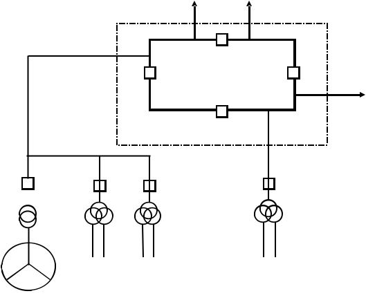
FIG. 6. Unit transformers connected at high voltage.
impedance of the transformer must also be compatible with the reactive power capability of the generator. In practice this means that the transformer impedance is usually in the range 10–18% of the transformer rating.
The standard practice for tap changers is different in different countries. In some Member States, the generator transformer has an off-load tap changer, and is operated on a fixed tap position, once the tap position has been established and agreed with the TSO. In other Member States the TSO may require that the generator transformer has an on-load tap changer. In either case, the choice of tap changer and tap position must take account of the reactive power absorbed by the transformer (which depends on the impedance of the generator transformer), and of the need for the generator to supply reactive power (grid voltage low) or absorb reactive power (grid voltage high).
8.5. UNIT TRANSFORMER DESIGN AND SIZING
The size (rating) of the unit transformer should be chosen so that it can supply the maximum continuous load of the auxiliaries including the load of battery chargers and an allowance for future increases in the auxiliary load, and permit the starting of the largest motors. The maximum auxiliary load of current reactor designs is typically around 5–8% of the rated electrical output. The design of the unit transformer must satisfy two conflicting objectives that the impedance should be high enough to limit the short circuit current to an acceptable level, but be low enough to limit the voltage drop through the transformer, including the additional voltage drop that occurs when starting large motors.
The unit transformer may have an on-load tap changer or an off-load tap changer. Whichever tap-changer is chosen, it must be possible to maintain the voltage to the electrical auxiliaries within the necessary range for the full
36
range of auxiliary load, and the full range of variation of the grid voltage or generator terminal voltage. This should include the ability to allow reactor start up when the grid voltage is low. Computer studies should also be carried out to verify the dynamic behaviour of the auxiliary motors for the transformer design that has been chosen.
In practice, the design and sizing of the unit transformer may be carried out as follows:
(1)Establish the largest power loading, which normally corresponds to the nuclear unit at full power;
(2)Decide the number of windings (for example two-winding or three winding transformer) and hence the power rating of each winding;
(3)Carry out a calculation of short-circuit currents to check that the rating of the circuit breakers is compatible with various operations considered;
(4)Deduce the maximum value of the reactance of the unit transformer, starting from the tolerances on the impedances of power transformers;
(5)Use computer transient studies to check that the rating of the unit transformer is compatible with various events on the transmission system (close short-circuit, voltage dip, islanding following a grid fault).
The results of calculations of short-circuit currents or electrical transients, and changes in the input data may require the design and sizing of the unit transformer to be re-assessed. If it is necessary to change the sizing of one element of the electrical supply chain then the validation studies must be repeated.
8.6. STATION TRANSFORMER DESIGN AND SIZING
As for the unit transformer, the design of the station transformer must satisfy two conflicting objectives that the impedance should be high enough to limit the short circuit current to an acceptable level, but be low enough to limit the voltage drop through the transformer, including the additional voltage drop that occurs when starting large motors. The size (rating) of the station transformer should be chosen so that it can supply the maximum continuous load of the auxiliaries including the load of battery chargers and an allowance for future increases in the auxiliary load, and permit the starting of the largest motors.
As explained in Section 8.3, in most nuclear units the normal supply to the auxiliaries is via the unit transformer, so for these nuclear units the station transformer spends most of the time energized from the grid but carrying no load.
The station transformer may have an on-load tap changer or an off-load tap changer. The choice of tapchanger must ensure that the voltage supplied to the auxiliaries is within the normal range when the auxiliaries are supplied via the station transformer, and that the voltage on the low voltage winding of the station transformer is compatible with its continuous voltage rating when it is energised from the transmission system but not supplying load. These conditions must be met for the full range of variation of transmission system voltage.
The design and sizing of the station transformer may be carried out similar to the unit transformer as described in Section 8.5.
8.7. GENERATOR DESIGN AND SIZING
The generator size and rating should be chosen so that the generator is able to accept the full power supplied by the reactor, including an allowance for possible future power increases.
The TSO may specify the range of power factors, and hence the range of reactive power that the generator should be capable of supplying or absorbing. The wider the range of reactive power is that is required, the larger will be the physical size of the generator. The range of reactive power required may also influence the design of the generator transformer.
The TSO may specify the performance required from the generator excitation system (AVR), in order to ensure transient and dynamic stability. This may include the requirement for the excitation system to be fast acting and have a high ceiling voltage. The NPP operator should carry out studies to establish the maximum voltage that may occur after a loss-of-load event, as this will be affected by the speed of the AVR and the ceiling voltage. This maximum voltage must be compatible with the allowable voltage range of the electrical supplies via the unit
37