

Schluesseltech_39 (1)
.pdf11.16 |
R. Zorn |
and because the Fourier transform of an exponential decay is a Lorentzian the incoherent scattering function is
1 DQ2 |
(11.60) |
Sinc(Q, ω) = π ω2 + (DQ2)2 . |
This function is centred around ω = 0, and for that reason the scattering is called quasielastic. This is typical for diffusionlike processes in contrast to vibrational processes which yield (phonon) peaks at finite energy transfers. For this reason, many textbook authors distinguish between inelastic and quasielastic neutron scattering instead of subsuming the latter under the former as done here6.
From expression (11.59) one can see that Iinc(Q, t) decays faster with time for larger Q and from (11.60) that Sinc(Q, ω) is getting broader. This is understandable because Q defines the spatial resolution of a neutron scattering experiment in a reciprocal way. So a larger Q means observation on shorter distances which can be travelled faster by the diffusing particle.
Finally, one can see that
|
inc |
|
− |
Q2 |
6 |
|
|
I |
|
(Q, t) = exp |
|
|
r2 |
. |
(11.61) |
|
|
|
|
Because this expression is derived independently of the specific form of σ(t) in (11.54) it is generally valid if the distribution of displacements Gs(r, t) is a Gaussian. Even if this is not the case, equation (11.61) is often a good low-Q approximation called the Gaussian approximation7 and is the dynamical analogue of to the Guinier approximation of static scattering.
In general, the incoherent intermediate scattering function cannot be derived from the meansquare displacement alone. Because equation (11.61) is the first term of the cumulant expansion exp(aQ2 + bQ4 + . . . ) of Iinc(Q, t) [20] the mean-square displacement can be calculated as
|
r2 |
|
= |
lim |
6 |
ln Iinc(Q, t) |
or |
(11.62) |
||||
Q2 |
||||||||||||
|
− Q |
→ |
0 |
|||||||||
r2 |
|
= |
− |
|
dQ2 |
Q=0 . |
|
(11.63) |
||||
d ln Iinc(Q, t)
By replacing Iinc(Q, t) by its value at infinite time, the EISF Sincel (Q), the limiting mean-square displacement of a confined motion can be obtained. This is the principle of the elastic scan
technique often used on neutron backscattering spectrometers [21].
6 There are two reasons for the choice made here: (1) The correlation function approach is also applicable to phonons. So, if this method is used, there is no conceptual difference between the treatment of vibrations and diffusion. (2) There are models as the damped harmonic oscillator which yield a continuous transition between inelastic scattering in the underdamped case and quasielastic scattering in the overdamped case.
7 In the literature, denominators 1, 2, and 3 are also found in this expression. Most of these formulae are nevertheless correct. Some authors use r2 as mean-square displacement from an average position (what is called u2 here). Then, 3 is the correct denominator because of r2 = 2 u2 (footnote 5). If the displacement is considered only in one coordinate ( x2 ), then 2 is the right denominator.
Inelastic Neutron Scattering |
|
11.17 |
„White“ neutron beam |
Axis 2: |
|
from reactor |
Sample |
|
|
θ |
Detector |
|
|
|
|
|
|
Axis 1: |
|
|
Monochromator |
|
Axis 3: |
Crystal |
|
|
|
|
Analyzer |
|
|
Crystal |
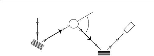
Fig. 11.6: Schematic setup of a triple-axis spectrometer.
11.3Instrumentation
11.3.1 Triple axis spectrometer
The basic objective of inelastic neutron scattering is to measure the momentum transfer q = k − k and the energy transfer ω = E − E. This task in general requires a monochromator for the incoming neutron beam and an analyzer for the scattered neutrons. In the most straightforward setup, the triple-axis spectrometer (3AX), one uses the Bragg planes of crystals similar to the diffracting grids in an optical spectrometer (figure 11.6).
Axis 1 turns the monochromator crystal. By doing this the neutron wavelength fulfilling the Bragg condition can be changed. In this way the wave vector k = 2π/λ of the neutrons impinging on the sample is determined. Axis 2 turns the arm carrying the analyser crystal around the sample position. This defines the scattering angle 2θ. Finally, axis 3 turns the analyser crystal around its own axis such that only the desired k is admitted to the detector.
For a given setting of axis 1 all points in the kinematically allowed (Q, ω) area (see Fig. 11.2) can be addressed by suitable settings of axis 2 and 3. E.g., for the study of phonons usually a ‘constant-Q scan’ is performed where Q = k − k is held constant and only ω = E − E is varied. For this purpose a coordinated change of the angles of axis 2 and 3 is required which is accomplished by computer control.
Historically, the triple-axis spectrometer is the first inelastic neutron scattering instrument. The first prototype was constructed in 1955 by Bertram N. Brockhouse. In 1994, Brockhouse received the Nobel prize for this accomplishment (together with Clifford G. Shull for the development of neutron diffraction).
The 3AX spectrometer is still widely in use for purposes where a high Q resolution is necessary and only a small region in the (Q, ω) plane has to be examined. This is mostly the study of phonons and magnons in crystals. In other fields, e.g. for ‘soft matter’ systems, it has been replaced by instruments showing better performance. The most important ones will be discussed here: time-of-flight (TOF) spectrometer, backscattering (BS) spectrometer, and neutron spin
11.18 |
R. Zorn |
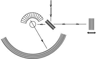
„White“ neutron beam |
l1 |
from reactor |
l0
Detector Bank
Monochromator Chopper
Crystal
Fig. 11.7: Schematic setup of a time-of-flight spectrometer with crystal monochromator.
echo (NSE) spectrometer.
11.3.2 Time-of-flight spectrometer
The main disadvantage of the 3AX spectrometer is that it can only observe one (Q, ω) point at a time. While for samples where the scattering is concentrated into Bragg peaks this may be acceptable, for systems with diffuse scattering a simultaneous observation of a range of Q vectors and energy transfers ω is desired. This is accomplished by surrounding the sample position with an array of detectors (figure 11.7). In addition the energy of the scattered neutrons E is here measured by their time of flight: A chopper in the incident beam defines the start time of the neutrons. The electronic pulse from their registration in the detector gives the end of their flight through the spectrometer. From the time difference the velocity of the neutrons can be calculated and from this in turn the energy transfer. The relation between time-of-flight and energy transfer is given by
ω = |
|
|
|
|
l12 |
|
− |
1 E . |
(11.64) |
|
|
|
l0 |
− |
E/mntflight |
|
|
|
|||
|
! |
|
|
|
" |
|
|
|
|
|
The monochromatization of the incoming neutron beam can either be done by Bragg reflection from a crystal or by a sequence of choppers which are phased in order to transmit a single wavelength only. The former principle usually yields higher intensities while the latter is more flexible for the selection of the incident energy E and attains better energy resolution.
Inelastic Neutron Scattering |
11.19 |
|
|
|
|
|
|
|
|
|
|
|
|
ω >PH9@ |
|
|
|
|
|
|
|
|
|
|
|
|
|
|
|
|
|
|
|
|
|
|
|
|
|
|
|
|
|
|
|
|
|
|
|
|
|
|
|
|
|
% |
|
|
|
|
|
|
|
|
θ 9 |
|
|
|
|
|
|
|
|
3 |
|
|
|
|
|
|
|
|
|
|
|
|
|
|
|
|
|
|
|
|
|
|
→ |
|
|
|
|
|
|
|
|
|
|
|
|
|
|
|
|
|
|
|
|
|
|
|
|
|
9% |
>PV@ |
|
|
|
|
|
|
|
|
|
|
|
|
− @ |
|
|
|
|
|
|
|
|
ω / >PH9 |
|
|
|
|
|
|
|
|
|
|
|
|
|
|
|
|
|
|
|
|
|
|
|
|
|
|
$ " |
|
|
|
|
|
|
|
|
|
|
|
|
|
|
|
|
|
|
|
|
← |
|
|
|
|
|
|
|
|
|
|
|
|
|
|
|
|
|
|
|
|
|
|
|
|
|
|
|
ω >PH9@ |
|
|
|
|
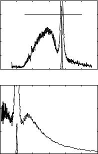
Fig. 11.8: Top: raw data from TOF spectrometer: neutron counts in a time channel of 10 μs during one hour registration time. The sample is a mesoscopically confined glass-forming liquid. The floating non-linear axis indicates the energy transfers calculated by equation (11.64). Because of the strength of the elastic scattering that part of the spectrum has been reduced by a factor of 200. Bottom: the same TOF data converted to S(Q, ω), elastic line reduced by factor 1000. The characteristic vibrational modes of the material at ω ≈ 1.7 meV (14 cm−1) become only visible after the transformation.
Table 11.1 shows some representative TOF instruments with their basic specifications. Depending on the desired incident wavelength the instruments are constructed either using neutrons directly from the reactor moderator (thermal neutrons, λmax ≈ 1.8 A)˚ or a cold source, where an additional moderation, e.g. by liquid hydrogen, takes place (λmax ≈ 4 A)˚ . Thermal neutrons make a larger Q range accessible while cold neutrons yield better energy resolution. Therefore, the choice of the instrument depends on the system to be observed but in general ‘cold neutron’ instruments are preferred for inelastic neutron scattering in soft matter systems.
A variant of the TOF spectrometer exists on spallation sources, the inverse time-of-flight spectrometer. Because the neutrons are produced in pulses by a spallation source one can use their creation time to start the TOF clock and in principle there is no need for a chopper. In this way all neutrons can be used in contrast to conventional TOF spectrometers which use only a few percent. Then usually the incident energy is measured by the time-of-flight and the final energy is kept constant by a fixed set of analyzer crystals (“inverse geometry”). By putting those crystals into near backscattering postion (see next section for details) it is possible to obtain a very good energy resolution already close to true backscattering spectrometers. Of course as a direct consequence of the good resolution function the count rates are low, especially with current

Inelastic Neutron Scattering |
11.21 |
„White“ neutron beam from reactor
Detector Bank |
Monochromator |
|
Crystal |
Deflector
Crystal
Sample 
Doppler motion
Analyser Crystals
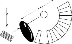
Fig. 11.9: Schematic setup of a backscattering spectrometer.
Instrument |
Type |
λ [A]˚ |
Qmax [A˚ −1] |
ω [μeV] |
ωmax [μeV] |
IN16 (ILL) |
CD |
6.27 |
1.9 |
0.2–1.0 |
15 |
IN10B (ILL) |
CH |
6.29 |
2.0 |
1.5 |
120 |
IN13 (ILL) |
TH |
2.23 |
5.5 |
8 |
300 |
SPHERES (JCNS) |
CD |
6.27 |
1.8 |
0.7 |
30 |
Table 11.2: Basic specifications of representative neutron time-of-flight spectrometers. Instrument types: CD–cold, Doppler monochromator; CH–cold, heated monochromator; TH– thermal, heated monochromator. The maximal Q and the energy resolution ω depend on the incident wavelength; the upper limits of their ranges correspond to the lower limit of the incident wavelength λi and vice versa.
the expense of intensity. (2) The second passage of the scattered neutrons through the sample causes additional multiple scattering and absorption. Both problems can be avoided by leaving exact backscattering condition but with the consequence that the energy resolution degrades.
So far it seems that the backscattering instrument can only observe elastic scattering (E = E) if the same crystals are used for monochromator and analyzer. In order to do inelastic scattering one has to change either E or E . It turns out that this is much easier for the incident energy by either using a moving monochromator (Doppler effect) or a heated monochromator (thermal expansion modifying the lattice plane distance d). The latter technique usually allows larger energy transfers. For very large energy transfers, different crystals are used for monochromator and analyzer, yielding an offset of the whole ω range. Table 11.2 comprises specifications of representative BS spectrometers.


11.24 |
R. Zorn |
we have to average the factor cos(φ − φ) weighted by S(Q, ω) to get the reduction of count rate at the detector, the effective polarization
|
∞ |
S(Q, ω) cos(ωtNSE)dω |
|
|
|
P (Q, tNSE) = |
−∞ |
∞ |
S(Q, ω)dω |
. |
(11.69) |
|
|
−∞ |
|
|
|
Firstly, we note that S(Q, ω) in this expression usually is the coherent scattering function. In principle, similar arguments can used for incoherent scattering because a well-defined fraction of neutrons changes its spin. This leads to a “negative echo” because the majority of neutrons invert their polarization. But because this effect is only partial (e.g. 2/3 for Hydrogen nuclei) it is much more difficult to observe. Only recently, NSE spectroscopy could be applied successfully to incoherently scattering samples.
Secondly, expression (11.69) reverses the temporal Fourier transform of equation (11.21) and therefore the result of the NSE experiment
P (Q, tNSE(B)) = |
I(Q, tNSE(B)) |
(11.70) |
|
I(Q, 0) |
|||
|
|
is the normalised intermediate scattering function. This function is often more understandable and easier to interpret than the frequency dependent scattering function.
In order to estimate typical Fourier times tNSE which can be accessed by NSE we consider maximum fields of B = B = 500 Gauss in precession coils of l = l = 2 m length operating at λ = 8 A˚ . Then (11.68) results in a time of about 10 ns which can be reached.
From this equation it also becomes clear that the most efficient way to enlarge this time is to use longer wavelengths because λ enters in the third power. This in turn reduces the accessible Q range which constitutes a drawback for studies on low molecular materials but not for the large scale properties of polymers which have to be observed at low Q anyway.
Typical NSE spectrometers with their specifications are listed in table 11.3. NSE spectrometers are very flexible instruments often used with different setups of which only “typical” ones have been included. As special features have to be mentioned that IN11 and SPAN have one-dimensional detector arrays which span 60◦ and 150◦ degrees respectively, allowing the simultaneous observation of a range of Q values. The instruments IN15 and J-NSE have twodimensional detector arrays which can be used for studying anisotropies but cover a smaller angular range. IN15 uses a focusing mirror in order to increase neutron flux which would be otherwise very low due to its long precession coils.
Acknowledgment
The author thanks Matthias Muthmann for critical reading of the manuscript.
Inelastic Neutron Scattering |
|
|
11.25 |
||
|
Instrument |
λ [A]˚ |
Qmax [A˚ −1] |
tmax [ns] |
|
|
IN11 (ILL) |
4.5–12 |
0.9–2.4 |
2–45 |
|
|
IN15 (ILL) |
8–25 |
0.13–0.4 |
30–1000 |
|
|
J-NSE (JCNS) |
4.5–16 |
0.4–1.5 |
10–350 |
|
|
SPAN (HMI) |
2.5–10 |
1.2–4.9 |
0.2–10 |
|
Table 11.3: Basic specifications of representative neutron spin echo spectrometers. The maximal Q and the maximal Fourier time tmax depend on the incident wavelength; the upper limit of the Q range and the lower limit of tmax correspond to the lower limit of the incident wavelength λ and vice versa.
References
[1]This dictum is usually attributed to the Nobel prize winners B. N. Brockhouse and/or C. G. Shull. But to the knowledge of the author, no reliable quotation clarifying its true origin exists.
[2]S. W. Lovesey: “Theory of Neutron Scattering from Condensed Matter” (Clarendon Press, Oxford, 1984).
[3]G. L. Squires: “Introduction to the theory of thermal neutron scattering” (Cambridge University Press, Cambridge, 1978).
[4]G. E. Bacon: “Neutron Diffraction” (Clarendon Press, Oxford, 1975).
[5]G. E. Bacon (ed.): “Fifty Years Of Neutron Diffraction: The Advent Of Neutron Scattering” (Adam Hilger, Bristol, 1986).
[6]M. Bee:´ “Quasielastic neutron scattering” (Adam Hilger, Bristol, 1988).
[7] R. |
Zorn: |
“Fourier |
Transforms” in T. Bruckel,¨ G. Heger, D. Richter, |
R. |
Zorn |
(eds.): |
“Neutron Scattering” (Forschungszentrum Julich,¨ 2008, |
http://hdl.handle.net/2128/37180), chapter I.
[8]R. Zorn, D. Richter: “Correlation Functions Measured by Scattering Experiments”, ibidem, chapter 4.
[9]N. W. Ashcroft, N. D. Mermin: “Solid State Physics” (Holt-Saunders, New York, 1976).
[10]G. P. Srivastava: “The physics of phonons” (Adama Hilger, Bristol, 1990).
[11]H. Bilz, W. Kress: “Phonon dispersion relations in insulators”, Solid-state sciences, Vol. 10 (Springer, Berlin, 1979).
[12]B. N. Brockhouse, Phys. Rev. 106 859 (1957).
[13]G. Placzek, Phys. Rev. 86 377 (1952).
[14]J. L. Yarnell, M. J. Katz, R. G. Wenzel, S. H. Koenig, Phys. Rev. A 7 2130 (1973).