

Drewett_1999_Field_Archaeology
.pdfRECORDING SITES |
67 |
Figure 4.9 Surveying with a level: the line of collimation.
used for levelling: they are used for calculating distance. When you view the landscape through the telescope, the horizontal cross-hair in effect projects an imaginary horizontal line across that landscape. In some levels this image is inverted.As the level can be rotated through 360° on the tripod, this level line can be sighted around the visible landscape. This imaginary line is really an arbitrary level plane being superimposed over the landscape, and is known as a line or plane of collimation. Both the transit and theodolite can be used in the same way as a level to throw out a plane of collimation. Their advantage over a level, however, is that they can be tilted to take readings up or down slopes while the level must remain rigidly level. From a field archaeologist s point of view, however, the level is very strong and less prone to damage than more sensitive equipment.
The second piece of equipment required for levelling is the surveyor s staff, in effect a giant ruler usually 4 m or 12 ft long, which either folds or is telescopic. The staff is marked in alternating red and black segments, divided into metres and centimetres, or feet and inches.As the staff is moved around the site, the readings taken by sighting the cross-hair in the level against the staff will be seen to vary. Lower readings indicate that the land is rising in relation to the plane of collimation, while higher readings show that the land is falling. To make sense of these rises and falls, the survey must be undertaken systematically and tied to a benchmark or, if none is available, you can create your own temporary benchmark.
The benchmark is the starting point of your levelling survey. In Britain the Ordnance Survey have cut permanent benchmarks on structures like churches and public buildings. These are an inverted V with a line on top. The actual benchmark level is the horizontal line. If no benchmarks are available you can create your own temporary benchmark and give it an arbitrary value, say 50 m. This will enable you to produce a site survey with contours, but not to relate it to other sites or the wider landscape.
The level is set up as close to the site of the survey as possible, but so that the benchmark can be seen. The staff is then held on the benchmark, not on the ground below, and a reading taken. This is known as a backsight. The value of the line of collimation is then calculated by adding the reading on the staff to the value of the benchmark. If the benchmark had a value of 50 m and the staff reading is 1.4 m, then the line of collimation has a value of 51.4 m (Fig. 4.9). To establish the relative height of spots on the ground the staff is placed on these spots, readings

68 FIELD ARCHAEOLOGY
Figure 4.10 Surveying with a level: moving stations, foresight and backsight.
taken on the staff, and then these readings are subtracted from the value of the line of collimation. So if the line of collimation has a value of 51.4 m and the staff reading is 3.2 m, then the actual height of that spot is 48.2 m. This is known as a reduced level.
If your benchmark is close to your survey site, then you may be able to turn the level from its backsight (onto the benchmark) directly into the survey area. These forward sights are then known as foresights. However, if you cannot do this, perhaps because the land rises and falls too much or there are trees in the way, you may need to move the level or change station . This is done by taking a foresight to the surveyor s staff and then, with an assistant holding the staff still in the same spot, moving the level to the other side of the staff and having a reading taken back to it (a backsight). The difference between the foresight and the backsight indicates how much the new line of collimation is above or below the previous line (Fig. 4.10). This process can be repeated until the site is reached and the level of the final line of collimation calculated.
To produce a contour survey of the site you can either chase a contour or interpolate contours from a grid of spot heights. To chase contours, the person holding the staff moves it along a roughly estimated contour line, moving it up and down slope until identical readings are found, say 45 m. The spot is then marked with a peg or surveyor s arrow and located using any of the techniques mentioned earlier in this chapter. This technique produces very accurate contours (although between spot heights the contours remain estimates) but can be timeconsuming, particularly if the person holding the staff is not very experienced. More usually a contour survey is produced by gridding the site and taking spot heights on the corners of each grid square. The smaller the grid squares are, the more spot heights will be recorded and the more accurate the contour survey will be. The more accurate the survey is, the longer it will take to produce. To produce a contour plan the grid is drawn at a reduced scale on a plan and the reduced spot heights marked on each grid corner.Actual contours are then interpolated from these spots. This is done first by estimating their position in relation to the fixed points on the grid lines. The points on the lines with similar value, say 45 m, 45.5 m, 50 m and so on, are then joined by curved lines to produce contours.
Levels can also be used for measuring distances by using the stadia lines already mentioned. These are the short cross-hairs visible through the telescope lens (Fig. 4.11). By sighting on a staff, two readings can be taken, one with the upper cross-hair and the other with the lower

RECORDING SITES |
69 |
Figure 4.11 Stadia hairs in a level.
cross-hair. The stadia lines have been calibrated so that by subtracting the lowest staff reading from the highest and multiplying by 100, the distance from the level to the staff is calculated.
The advantage of both the transit and the theodolite over the level is that they can be tilted and so take readings above and below the line of collimation. This has obvious advantages if the site is undulating or has any steep slopes. The engineer s transit is widely used in the USA but is virtually unknown in Britain, while the theodolite is commonly used in Britain but is less common on American archaeological surveys. They function in a very similar way. Both have three elements: the transit or theodolite, a heavy-duty tripod, and a staff. The staff is the same type as was used with a level. Both instruments are set up on their tripod and levelled using built-in spirit levels.
Reading a transit or theodolite is similar to reading a level. The centre hairline in the lens is used for taking levels, while the stadia lines are used for distance. Horizontal bearings are taken using a 360° horizontal circle. This can be used to take very precise angles. In Britain the 360° circle is divided in degrees, each degree is subdivided into 60 minutes, and each minute into 60 seconds. Angles are then quoted as 242°14 32? which, as you can see, gives a very precise horizontal angle which can be used in both surface surveys and for precise excavation recording.
70 FIELD ARCHAEOLOGY
The additional reading that theodolites and transits can give, which levels cannot, is the vertical angle. The use of this angle introduces a need for basic trigonometry. The calculations required can be performed using formulae, but more usually tacheometric tables are used. These can be found in many surveying manuals, and appear as Appendix 3 in Martha Joukowsky s A complete manual of field archaeology (Joukowsky 1980).
As with most levels, the multiplication factor for distance readings for stadia is 100 in modern instruments. This factor is known as K . To calculate distance, the stadia readings (that is, the top and bottom short lines in the viewfinder) are read off from the staff. The difference between these two readings is called s . The third reading taken is the angle the theodolite or transit has been tilted from the horizontal. This angle is known as V . Distance is then calculated with the formula
Distance = Ks (cos2)V
Height can also be calculated using the formula:
Height = Ks (cosV) sinV
The importance of the transit and theodolite is that they enable you to survey more accurately where the ground surface is not level than would be possible using the previously mentioned techniques.
Much of the surveying equipment described so far is becoming redundant as electronic surveying equipment becomes more readily available, cheaper and easier to use. There will, however, always be occasions or parts of the world where simple, cheap surveying techniques will be used. A good surveyor should be able to switch methods and equipment as the need arises. If your total station dies, high in the Andes on the last day of a survey, a couple of tapes could save a very expensive revisit to the site.
Electronic Distance Measurement (EDM) equipment was first developed to be attached to theodolites but now the EDM and theodolite are built into a single housing and this is then known as a total station (Fig. 4.12).As all data can be recorded digitally, computers may be used throughout the survey to record data in the field and to draw up the final plan. The EDM or total station is set up on a solid tripod and, when switched on, a built-in transmitter throws out a beam (for example of infra-red) which is returned from a reflector held at the position you want to locate. The electronics within the machine calculate distance from the length of time the beam takes to reach the reflector and return. This time will be affected by height above sea level (or pressure) and temperature. These data will have to be entered into the EDM or total station to enable a correction to be made.
The form and key pad of EDM and total stations vary, but essentially distances, angles and heights can be recorded. Generally this is now done by automatic recording which eliminates all need for writing in the field. The EDM and total station can be used for setting out survey frameworks or grids, but area surveys are approached somewhat differently. With pre-electronic surveying, measurements were generally taken in relation to lines, baselines, triangles and survey frameworks. With electronic surveying these are not required, and the survey takes place in the area around the equipment so there is a change from linear recording to area recording.

RECORDING SITES |
71 |
Figure 4.12 Total station.
Spots are recorded in direct relationship to the position of the surveying equipment. These areas can be very large, so the surveyor at the total station may need to communicate with the person moving the prism who could be one as much as a kilometre or so away. The only effective way to do this is to use a walkie-talkie radio.
To undertake a survey, the total station or EDM is set up at a suitable position within the survey area, preferably where all or as much as possible of the site can be seen. Points to be recorded on the ground are located, including buildings and field banks, together with the archaeological features. These spots are either numbered consecutively or, if the plan is to be computer-drawn, by using the codes required by the package, which will also have to inform the computer what type of feature to draw. Do the points recorded represent an earthwork to be drawn with hachures, or is it a masonry building? Many computer drafting packages can also draw contours. This generally requires level values to be recorded on a regular grid, although some can produce contours from random levels. If using random levels they must be well spread over the site, or the contours will look somewhat unconvincing. Contours are essentially lines but spot-height data can also be used to record surfaces which can produce images close to true surface representation. These are digital elevation models (DEM) sometimes known as digital terrain models (DTM). The DEM has become an important element in the construction of Geographic Information Systems (GIS).
Whatever surveying techniques are used, they will end up with an image of the site. Traditionally, and still generally for publication, conventions are used to present a picture of the
72 FIELD ARCHAEOLOGY
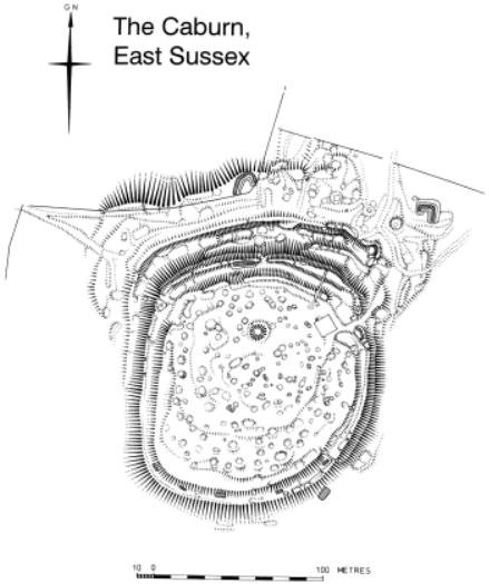
Figure 4.13 Hachured survey of Mount Caburn, Sussex (survey by A. Oswald and D. McOrmish. Crown copyright: RCHME).
surface undulations of a site. Banks, ditches, pits and hollows are represented by hachures (Fig. 4.13). These enable banks and ditches, for example, to be clearly shown whereas if they were indicated by contours they might be lost in steeper natural slopes of the hillside. Used skilfully, either by a draftsperson or a computer, they can be used to show very slight variations in slope. However, computer-generated three-dimensional terrain-modelling and hill shading can generate images which nolongerrequireconventional cartographicconventions.Withvertical exaggeration even the slightest landscape features can be clearly imaged.
RECORDING SITES |
73 |
Photography
The third element of recording archaeological sites in the field is photography. One element of this is aerial photography, already considered in Chapter Three.The other element is producing a ground photographic record of landscapes, archaeological features and keyholes cut into the landscape, like natural river-bank sections which may show archaeological layers. Field survey, as opposed to excavation, often requires movement of equipment great distances and often by foot. A compact photographic kit is advisable for this type of work. The equipment required should be able to be packed into a standard photographic shoulder bag. A typical kit would include two 35 mm camera bodies, with either zoom lenses or 28, 50 and 200 mm lenses. Useful filters include UV (ultra-violet), polarizing, and yellow, red and green.Atripod may be taken but is often not needed in open country. Other accessories include a cable release, compass, scales and of course film (Dorrell 1989).
Films should include both black-and-white and colour. Black-and-white remains the basic film for archaeological record. The life of colour film is uncertain, and fading will occur unless storage is very carefully monitored in the long term. Panchromatic medium-speed film of 100 125 ISO is suitable for most field situations. Colour transparency or positive film is used for lecture slides and, more rarely, for publication. When it comes to colour-slide film, many photographers have their own personal preference, but in Britain Kodachrome film is widely favoured, with film speeds of 25, 64 or up to 200 ISO depending on conditions. Colour negative film is rarely used for primary field recording, although it may be used for temporary site exhibitions.
This is not the place to expand in detail on photographic principles (see, for example, Langford 1986) but certain elements should be remembered when taking photographs. Firstly a photograph does not give an exact scale image of what is in the field. Whatever is close will appear at a larger scale than what is at a distance, and if the image is all on the same plane, then the scale in the centre of the photograph will be smaller than at its edges. To produce an image more or less as the human eye sees it, a standard lens should be used. This gives an angle of view of about 45°, similar to a human eye. A wide range of other lenses can be fitted to 35 mm cameras, giving very wide angles (over 180°) and very narrow angles of down to 2°. Neither of these extremes is particularly useful in archaeology, especially very wide-angle lenses which create a very distorted image.An image like a building or a river-bank section will appear very distorted if photographed very close. Distortion can be reduced by photographing from further away and then, if using negative film, printing only the part of the image required.
Photographing close images may also create problems of focus. There is only a limited distance in front and behind the spot being photographed that is in focus, that is the depth of field . This may not create a great problem in survey photography, but can create real problems when photographing excavations and objects (see Chapters Seven and Ten). In field survey photography, light is usually no great problem, and so by decreasing the aperture of the camera lens the depth of field is increased.

74 FIELD ARCHAEOLOGY
Figure 4.14 Landscape photographed in evening sun to cast shadows.
Photographing landscapes in which archaeological sites occur is relatively straightforward, but careful selection of viewing point, time of day, weather and light conditions can greatly enhance the image, as can the use of filters.An undulating landscape will look flat if photographed with high midday sun or without any sun. Early morning or late evening sun will cast shadows, giving the landscape a three-dimensional image (Fig. 4.14). This will also apply to photographing earthworks, which may effectively vanish without any shadow. There will be spots in the landscape which give the best overviews. Usually, but not always, these are higher points. With black-and-white film, red or yellow filters can be used to reduce distant haze, as can ultra-violet filters. In colour photography of landscapes, polarizing filters will enhance the contrast between blue sky and clouds, and sharpen the distant image. Although in general all archaeological photographs should contain a clear scale, landscapes usually contain some indication of scale in the form of buildings or trees.To add an artificial scale introduces spurious accuracy as the scale in the foreground is different from that in the distance. A human figure or two may, however, enhancethe composition of the photographand give a general indicationof scale. If photographing earthworks, the figures could hold ranging poles.
Photographing buildings or natural sections like cliffs creates more of a problem than general landscape photography. If photographed at ground level, the scale of the building or cliff face gets smaller higher up the face. This gives the effect of the face leaning. This effect can be reduced by taking the photograph from further away. This is, however, not always possible, in which case either a large-format camera with movements, or smaller format cameras with a shift
RECORDING SITES |
75 |
lens will be needed to rectify the photograph (Dallas 1980). Reasonably accurate elevation drawings can be traced from these photographs.
When taking archaeological photographs, proper record-keeping is an essential part of the process. Often one landscape or cliff section looks surprisingly like another. This becomes even more important in excavation photography where hundreds of photographs of similar features may be taken (Chapter Seven). In field survey it is best to make the photographic record in a note book rather than on the sort of pre-printed loose-leaf record form often used on excavation. The record should include:
1Film number
2Serial number of negative
3Full details of subject
4Direction from which photograph was taken (compass bearing)
5Date and time of day
In addition it may be worth recording photographic information to trace equipment problems or errors in the photographer s judgement.
6Equipment used
7Type of film
8Lens
9Stop and exposure
As with much in field archaeology, a little extra time and care spent in the field can save an enormous amount of time when attempting to sort out records for archive or publication after the field season.
CHAPTER FIVE
Planning the excavation
It must never be assumed that excavation is an essential part of any archaeological fieldwork. Indeed, if the questions under investigation can be answered using the battery of non-destructive techniques now available to archaeologists (Chapter Three), then excavation should not be considered. The archaeological resource in the field is finite and diminishing. Each excavation reduces this resource. The excavation of sites about to be destroyed for non-archaeological reasons, like building development, can usually be justified on archaeological grounds if all attempts at preservation have failed. If, however, the site is not under threat, the value of excavation in increasing knowledge must be carefully considered.
This is, however, in no way suggesting that research excavations should not be undertaken. Without proper, well-planned research excavations, archaeology as a discipline could become as fossilized as many of the sites it studies. No excavation should, however, be undertaken lightly. They are expensive, time-consuming, and often very stressful. Many of the problems encountered on excavations can be reduced by proper pre-planning and careful use of human and financial resources.Above all a flexible approach can save time, money and stress. Remember there is no right way to excavate. There is a range of possible approaches.
Permission, funding and the law
The first stage in planning an excavation is to establish whether you can actually get permission to dig the holes you want to dig, that you can afford to dig the holes, and that legally you can dig the holes and do it safely. No field archaeologist should ever dig holes without proper permission. Firstly, establish whether the site has legal protection. In some countries named archaeological sites are protected while in others all archaeological sites are protected.
Practically every country in the world has some legal control on what can and cannot be done to archaeological sites. In some countries the laws with terms like Ancient Monuments or Archaeology may not be either the most important or effectiveActs. In Britain, for example, probably more sites are protected on a day-to-day basis under the Town and Country Planning Acts than under the Ancient Monuments and Archaeological Areas Act, 1979. This is because
76