

Drewett_1999_Field_Archaeology
.pdfFINDING ARCHAEOLOGICAL SITES |
57 |
survey base or laboratory, 50 mg of soil is placed on filter paper and a couple of drops of ammonium molybdenate in hydrochloric acid are added. A dilute solution of ascorbic acid is made by adding 0.5 g to 100 ml of distilled water, from which two drops are added to the sample after thirty seconds.Ablue ring then develops on the filter paper, which is directly proportional to the amount of phosphorus in the soil. The reaction is stopped after two minutes by placing the filter paper in a 50 per cent solution of sodium citrate in water (Eidt 1977). Essentially, the deeper the blue, the more phosphorus there is present in the soil. This can be assessed very approximately by eye, or more accurately by using a colorimeter.
Although phosphorus is perhaps one of the clearest and easiest chemical residues to locate in the soil, other chemicals like copper and lead may be associated with specific types of human activity, and degraded lime mortar may be traced by higher concentrations of calcium locally in the soil (Clark 1990).
Accidental discovery
Although archaeologists have a battery of survey, remote sensing and chemical techniques available to locate archaeological sites, it remains true that many, if not most, new archaeological sites are found by accident. Classic accidental discoveries like the Lascaux painted caves or the Xian terracotta army are well known, but in virtually every disturbance of the earth s surface some archaeology is located. Some of this archaeology may be so recent, like flower-pot sherds or drain pipes, as to be of little interest to archaeologists, but much more is missed by having no trained observer to locate and record the information.
Many archaeological discoveries are made by building workers, farmers, quarry workers and just casual passers-by. A tiny fraction of these discoveries comes to the attention of archaeologists. Usually casual finds are reported to local museums. it is essential that the archaeologists in the museum or elsewhere show enthusiasm for these discoveries, even if they are not of major importance. One bad experience by a member of the public and they will never bother to bring their discoveries in again, and next time it may be a terracotta army!
There are also accidental or partly-accidental discoveries made by archaeologists. Whenever surveying an area using any techniques, field archaeologists should take the opportunity to look into any available keyholes to see what lies buried. These keyholes are often very short-lived and the opportunity may not arise again.
Keyholes can be broadly divided into natural and humanly-produced. Natural keyholes include burrow upcast, thrown up by burrowing animals, the root bases of uprooted trees, and natural erosion by rivers and the sea. River banks and low cliff lines can provide a ready-made cross-section through the landscape. Human keyholes are usually even shorter-lived. These include pipe trenches, foundation trenches of new buildings, holes dug for fence posts, or even holes dug for graves.
Having located an archaeological site it is the responsibility of the archaeologist either to record it, or at least inform relevant authorities who can record it.
CHAPTER FOUR
Recording archaeological sites
The recording of archaeological sites discovered in the field essentially has three elements: a written description of the site, a survey including plans and elevations, and a photographic record. Many of these techniques are of course the same, or similar to, those that we will meet again in Chapter Seven when recording excavated features. The record described in this chapter may be as far as the field archaeologist goes, or it may be a stage before excavation. It must not be presumed, however, that excavation is, or should be, the final element of any fieldwork. In fact the presumption should be that excavation is only a last resort if all non-destructive techniques of investigation fail to answer the questions posed. Excavation, being totally destructive, allows questions to be asked only once. If excavation recording is very precise, as it should be, then some questions can be asked of the record, but never again of the whole site.
Written description
The written description of a site in the field should be properly integrated with survey and photographic data. Even with the finest prose, a written description inevitably can mean slightly different things to different readers, particularly if translated into other languages. As long as conventions are adhered to, surveys and photographs usually do not present this problem.
How the description of a site is written will depend very much on how the record is to be used. If you are recording the site simply to record its existence on, for example, a Sites and Monuments Record, then the use of a pre-printed record form in the format of the Sites and Monuments Record is advisable. The basic fields of record have already been described in Chapter Three andconsist of aunique referencenumber, administrativearea,address,cartographic reference, type of site, date and condition of site. This should be sufficient for future workers to locate the site again. If, however, you are attempting to interpret the site and pass your interpretation on to others, then a more detailed written description of the site will be required. Such descriptions are usually tied into a topographical survey.
Interpretative surveys and their written description go right back to the beginnings of field archaeology. As early as the seventeenth century, field archaeologists like William Stukeley
58
RECORDING SITES |
59 |
(1687 1765) accurately described field monuments.At the beginning of the nineteenth century, field archaeologists such as William Cunnington were not only describing monuments, but also the sequences represented by them: A few feet further to the west from the large tumulus are two more barrows over which the great inner vallum [of Battlesbury Camp] passes (Cunnington 1975). This clearly describes a sequence of the earthworks.
The finest current descriptions of surface archaeology in Britain are those produced by the Royal Commission on Historical Monuments surveyors. Tight interpretative descriptions support fine surveys. Modern descriptions are usually more precise than those of earlier antiquaries and include measurements: A double-lynchetted track (d), up to 9 m in width, originates from beneath the east terminal of the southern entrance and runs intermittently in a north-east to south-west direction for some 250 m before being truncated by circular hollows (Donachie and Field 1994). However clear a description may be, it will only really make sense if accompanied by a field survey and photographs.
Archaeological surveying
Archaeological surveying uses all the techniques of land surveyors, but requires an archaeological input to interpret what is present and worth recording. Essentially, decisions have to be made throughout the survey as to what is natural as opposed to humanly-created, where the top and bottom of a bank is, whether this bit of earthwork overlaps, or is overlapped by, another earthwork.
Over the last decade or so, land surveying has been revolutionized by the introduction of Electronic Distance Measurement (EDM) equipment and the total station, together with the satellite-based Global Positioning System (GPS). However, many field archaeologists, for a variety of reasons, still have or wish to use less sophisticated and cheaper survey techniques. All survey data has the potential for inclusion in Geographic Information Systems (GIS), but naturally that collected in digital form requires less manipulation than traditional survey methods.
When selecting a traditional survey technique, the first thing to consider is precision or how inaccurate can you be. This requires thinking about the end-product. Most surveys are presented in a reduced form. These may be drawn at a scale of 1:20 for good detail, but then reduced even further for publication. The thickness of a pencil line represents about 1 cm on the ground at a scale of 1:20, so is there any point in taking measurements less than 1 cm, particularly if surveying earthworks? More usually surveys will be undertaken at even smaller scales like 1:100, 1:500, or even 1:1 000. The significance of precision becomes even less important as the scale becomes smaller.
The simplest form of surveying is a paced or sketch survey. This can be done either with very basic equipment like tapes, ranging poles and prismatic compass, or with no equipment at all. Such surveys are really suitable only for small, simple sites where great accuracy is not too important. If you do not have access to more advanced surveying equipment, however, sufficiently accurate plans can be produced.

60 FIELD ARCHAEOLOGY
Figure 4.1 Simple surveying by offsets.
Firstly, lay out a baseline. If the site is fairly small and you have two fixed points like a tree and a corner of a building, the shortest distance between these two points gives you a straight baseline. If you have no measuring equipment, you can pace along the baseline and then pace an estimated perpendicular to the point you want to locate (Fig. 4.1). This can then be done to locate any points within reasonable distance of the baseline.You can build in more accuracy by measuring your lines with tapes rather than paces, and using tapes, optical square or crosshead to construct the perpendicular. The best tapes to use are fibreglass or similar, 20 m or 30 m long. Longer tapes, which can go up to 200 m, create problems in rough country and wind.
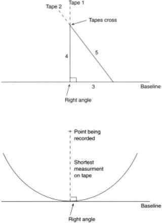
The crosshead consists simply of a metal cylinder with right-angle slots.You view one way along the baseline and then, viewing through the slots at right angles, lay out a perpendicular. The optical square is similar, but using prisms you can view along the baseline and at right angles at the same time. Ranging poles, red and white poles 2 m long made of wood or metal, are used as sighting markers. Using just tapes, a perpendicular can be made either by constructing a 3 4 5 triangle (as Pythagoras; see Fig. 4.2) or by putting the end of the tape on the point you want to locate and swinging the tape over the baseline. The shortest distance on the baseline as the tape is swung along it has to be a right angle (Fig. 4.3). This simple technique of surveying is reasonably accurate on level sites, but if there is any slope care must be taken to keep tapes level, and a plumb-bob should be used to locate positions on the ground below the level tape
RECORDING SITES |
61 |
Figure 4.2 Constructing a 3-4-5 triangle.
Figure 4.3 Establishing a right angle from a baseline by swinging a tape.
An alternative to offset surveying, using perpendiculars from a baseline, is triangulation. This, as the name suggests, involves constructing triangles. It can also be carried out from a baseline and is best done with two tapes. Two points are selected on the baseline and one end of each tape is pegged, at the points selected. This can be done with surveyor s arrows which are metal skewers, brightly coloured or with a flag attached to make them clearly visible. The other ends of the tapes are then crossed over the point you want to locate. By doing this you have constructed a triangle with three known sides, so you have fixed the point of the apex (Fig. 4.4).
For larger sites it is advisable to use a survey framework rather than a single baseline. In effect this consists of four baselines (the sides of the framework) with the shape of the framework fixed by measuring diagonals. Either offsets or triangles can then be laid off from the framework (Fig. 4.5).

62 FIELD ARCHAEOLOGY
Figure 4.4 Surveying by triangulation.
Figure 4.5 Surveying from a framework.
One of the oldest types of surveying equipment, still in use in some parts of the world and largely unchanged since its appearance in about AD 1600, is the plane table. Although rarely used where electronic surveying equipment is available, it is worth mention, partly because of its successful use over some 400 years, and partly because in many parts of the world it may be one of the most readily available pieces of survey equipment.

RECORDING SITES |
63 |
Figure 4.6 Plane table surveying.
The plane table consists of a drawing board (the plane table) mounted on a tripod. On this rests the alidade which is a straight edge with sights at each end. Most commonly, the plane table is used to produce plans of small earthwork sites by the radiation method. The plane table is placed level on its tripod in the middle of the earthwork. The point to be located is then sighted through the alidade and the sight line recorded by drawing a line along the edge of the alidade directly onto plastic tracing film mounted on the plane table. A tape is then used to measure from the plane table to the point being located. The distance is scaled down (say to 1:500) and measured along the sight line drawn on the plane table. The position of the first point has then been located. Each point to be measured can be located in the same way. The points are then joined up to produce the shape of the earthwork (Fig. 4.6).
An alternative way to produce a simple ground survey is to grid the site. This process can also be used to produce a field-walking grid or a grid laid out in advance of excavation.Asite grid, as the name implies, involves the construction of a regular pattern of squares over the area of interest. Actual squares are, of course, never laid out; just all or some of the corners of squares are marked in some way. For a short-lived grid, as used in field walking, this can be done with ranging poles. If the grid is to survive one or more excavation seasons, then steel pegs, perhaps even set in concrete, may be required but this will be further discussed in Chapter Seven. Having set up a survey grid, details of the site can be plotted by taking offset measurements from the grid lines, or triangulation from the lines or corner points.
64 FIELD ARCHAEOLOGY
To lay out a grid, a point of origin must be selected. This will be a fixed point outside the area to be surveyed. If the grid is to be used over several years for surveying, field walking and then perhaps excavation, it must be a permanent fixed spot which will not be disturbed by any future work. It is often convenient, particularly for reference and locating the grid on existing maps, for the grid to be orientated north south.Archaeologically, however, there is nothing significant in north south orientated grids. It is often done just for neatness.
It is possible to lay out an accurate grid using two people, half a dozen ranging poles, two tapes and, if on a sloping site, a plumb bob. For greater accuracy, particularly on sloping sites, it can be done with a theodolite or transit. Firstly lay out as long a line as you can from the point of origin along one side of the proposed grid. This can be done by sighting a line using ranging poles. A ranging pole is put in the point of origin and one surveyor stays with it. The other surveyor takes the other poles along the line to be set out.Asecond pole is then put in some 100 m or so along the line. If the grid is to be orientated north south, the second pole is set out using a prismatic compass. Both in the field and in writing up data, it should made clear that magnetic (not geographical) north is being used.Aprismatic compass is a simple hand-held compass with a prism, enabling you to read the compass bearing while looking between two sighting marks on the compass. These sighting marks are lined up with magnetic north and then the second ranging pole is moved into line with the sight marks. Intermediate poles can then be sighted in by eye.
The first surveyor at the point of origin will sight along the line. The second surveyor moves a pole slowly across the approximate area of the grid line. As it vanishes behind the first pole and hides the third pole, then all three poles must be in line. The line can then be projected on across the landscape by repeating the process down the line. If a 30 m grid is being laid out, then a tape is stretched from the origin along the line for 30 m and a peg put in the ground. This process is repeated along the full length of the line. It is important to tape horizontally along each 30 m length; if the ground slopes, raise the edge of the tape at the lower end until it is horizontal and then use a plumb bob to position the peg at ground level.
From this baseline, right angles are then laid out at the corner of each grid square, that is, every 30 m in the example we are considering. This can be done using two tapes and simple geometry. Either an equilateral triangle or a right-angled triangle is constructed. To construct an equilateral triangle over a 30 m point on the baseline, measure an equal distance (say 3 m) either side of the baseline peg, and fix the end of a tape at each point. Then unwind the tapes to 6 m each, and where they cross they will form an equilateral triangle with three sides of 6 m each.A line from the original peg through the apex of the triangle will therefore be at right angles to the baseline.
Alternatively a 3-4-5 triangle could be constructed from the peg on the baseline (Fig. 4.2). This is done by measuring 3 m to one side of the baseline peg along the baseline.Atape 5 m long is held with 0 m on this point.Asecond tape is held with its 0 m on the baseline peg and opened to 4 m. The 4 m and 5 m tapes are then crossed, and where they cross will give a right angle from the baseline peg. Right angles can, of course, also be laid out using a variety of surveying equipment, from crossheads and optical squares to transits and theodolites.

RECORDING SITES |
65 |
Figure 4.7 Fixing the position of a grid.
Having constructed a right angle, then a line at right angles to the baseline can be sighted out using ranging poles. This process can be repeated at every 30 m interval along the baseline until a grid of squares has been constructed. Laying out a grid using just tapes and ranging poles can be perfectly accurate, but inaccuracies can always creep in due to slope, tapes being moved by the wind, or surveyor problems (for example, misreading a tape or bad eyesight ranging out a line). To remove these problems always check the diagonals of squares created. If the length of the two diagonals are the same then it is a square. If one is significantly more than the other, recheck your layout. You must, however, consider whether a few centimetres matter. They do not matter in a field-walking grid or if surveying eroded earthworks.
A grid is only of any use, however, if you know where it is. To record this you need to fix the location of the point of origin of the grid. If you have clear, permanent fixed structures like buildings, then simply measure to a minimum of three fixed points. These points are likely to be on existing maps, so they can be located and your grid positioned in relation to them. If there are no close fixed points, then prismatic-compass bearings can be taken to fixed points further afield but clearly visible. Again a minimum of three points must be plotted (Fig. 4.7). This process can also be carried out with a transit, theodolite or total station. If working in an area

66 FIELD ARCHAEOLOGY
Figure 4.8 Surveyor s level.
where there are no good maps or fixed points in the landscape, then you may have to use a satellite Global Positioning System (GPS). These can be used to fix the position of any spot on the earth s surface in relation to orbiting satellites. Very cheap hand-held machines are available, particularly designed for sailors of small boats, but are accurate only to 15 m or so. More expensive systems, like the Leica System 200, however, can fix positions to an accuracy of about 1 cm.
The techniques described so far will enable you to produce a cheap, reasonably accurate plan of any simple site. They do not, however, provide any information about how the land rises and falls, how high your earthworks are, or whether the site is level or undulating. To gather this information you need to be able to record the height of different elements of the site. This is the process of levelling which, not surprisingly, can be carried out with an instrument called a level (Fig. 4.8), although it can also be done with other optical or electronic equipment to which we will return later.Although one often hears all levels on archaeological sites referred to as dumpy levels, in fact there are three types which vary mainly in the way in which they are set up. These are the dumpy, quick-set and automatic levels. All three have to be set level on a solid tripod. This is done by levelling one or more spirit levels built into the machine. In the dumpy this is done by raising and lowering three screws; the quick-set uses a ball and socket, while the automatic level simply involves one small central bubble which, when centrally located in a marked ring, results in an internal mechanism levelling the sight lines.
The level itself includes a telescope. When you look through the telescope you will see a vertical line and a horizontal level line. There are also two short stadia lines, but these are not