

prt%3A978-0-387-35973-1%2F16
.pdfModeling with Enriched Model Driven Architecture |
701 |
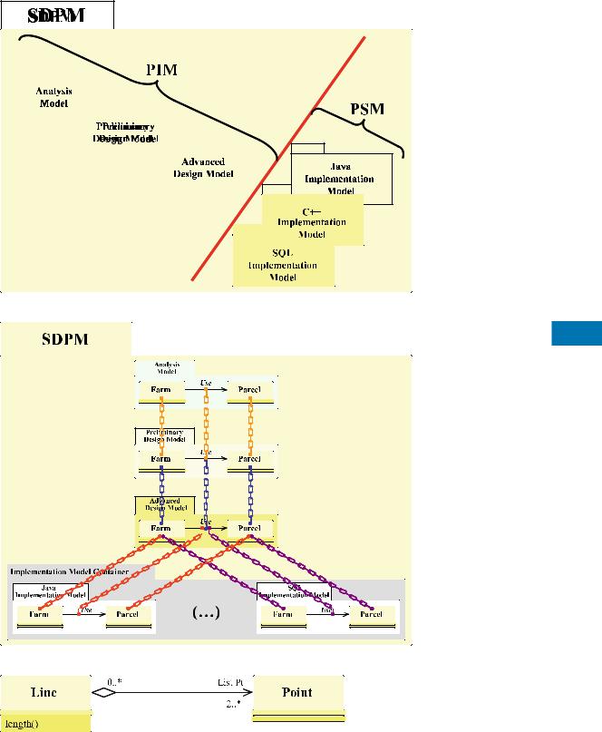
Modeling with Enriched Model Driven Architecture, Figure 1
Concepts separations and transformations
ed in PSMs, a PIM can be seen as a modiÞed subset of a PSM. Therefore, a PSM always derives from a model PIM through one or more transformations. Fig. 1 illustrates this separation and transformation. If different platforms are used for the implementations (e. g., same standardized model implemented into different organizations), then more than one PSM may be derived from the same PIM.
The previous transformations, called PIM/PSM transformations, are not the only ones. In fact, the authors of MDA mention, on the one hand, the existence of PSM/PIM transformations converting a PSM into PIM and, on the other hand, transformations whose models source and target are in the same fashion standard: PIM/PIM transformations or PSM/PSM transformations.
In the process of development, the PSM is not the last step since it is then necessary to project this model into a programming language. This projection is often considered to be a transformation.
In summary, the separation introduced by MDA can be seen as a solution of a more fundamental preoccupation: the capitalization of knowledge.
Historical Background
The Model Driven Architecture is an approach which expands the Object Management Architecture [5] without replacing it. The Object Management Architecture provides a framework to implement distributed systems [6] whereas the Model Driven Architecture deÞnes an approach specifying how to use the models during the development of an application.
The founding text of Model Driven Architecture is a recent OMG work that was approved in 2001 [5]. In 2003, this text was supplemented by a methodological guideline deÞning the main directives to apply this approach.
In 2003, Anneke Kleppe et al. wrote in their book entitled,
MDA Explained: The Model Driven Architecture-Prac-
tice and Promise [4], that this approach was Òstill in its infancyÓ. The following year, Anneke Kleppe, when interviewed about Model Driven Architecture [3], was quoted as saying, ÒCan we realistically look to build all of the J2EE code for an application from UML diagrams?Ó and ÒYes, it may take Þve, ten, or maybe twenty years before it will be common practice, but I believe it will become just that.Ó
These two statements explain that a lot of research has to be carried out so that this approach reaches its maturity. For over 20 years, R&D and commercial software engineering software packages have offered semi-auto- mated transformations between so-called ÒconceptualÓ and ÒphysicalÓ models, with more or less success with regards to their widespread usage. Nowadays, with the standardization impacts of MDA and UML, hope is returning. Currently, research works are mainly concentrated on the transformations of models to automate these transformations in order:
¥Firstly, to carry out a Full MDA process [3], i. e., a process automating the evolution of the models from the analysis to the implementation
¥Secondly, to increase the productivity during the devel-
opment and facilitate code reuse. |
M |
Scientific Fundamentals
The Enriched Model Driven Architecture is a framework for designing and implementing spatio-temporal databases following a MDA approach into a Full MDA process. This process includes the generation of the SQL code necessary to implement the spatio-temporal database. For that, a multimodel artifact and a panoply of transformations has been conceived and implemented.
In order to describe the spatial and temporal properties of the business concepts, the pictogrammic language of the Perceptory case tool [1] has also been adopted and implemented.
Principle of the Software Development Process Model (SDPM)
When an application is developed, one of the main preoccupations for a project manager and for the company in charge of the software development is the capitalization and reuse of the knowledge accumulated during the development.
The capitalization of knowledge is not just the problem of separating the business concepts and implementation concepts according to the MDA vision. The capitalization of knowledge is problematic throughout the development of an application. The Software Development Process Approach (SDPA) is a framework based on this report [7].

702 Modeling with Enriched Model Driven Architecture
As with each phase of the development, the type of mobilized knowledge is different. The idea of this new approach is to capitalize the knowledge of each one of the phases. For that, this new approach recommends dedicating a model at each one of the phases.
In order to materialize this new approach, a multimodel artifact, called the Software Development Process Model
(SDPM), has been conceived [7]. This multimodel artifact contains the different models corresponding to the phases of the software development process. In this vision, the Software Development Process Model is the MODEL of the application under development. Fig. 2 shows the Software Development Process Model for the development of software following the Two Track UniÞed Process method [8] derived from the UniÞed Process method. This Þgure also shows that the PIM/PSM separation introduced by MDA occurs when the project moves from the advanced design phase to the implementation phase.
Panoply of Transformations for a Full MDA Process [7]
Diffusion Transformation and Management of the Software Development Process Model In order to manage the different models, the Software Development Process Model has been endowed with a Diffusion transformation. This transformation Þrst clones a concept from a source model into the following model. Step by step, the concepts that are captured in the analysis phase and added into the analysis model are transferred into the implementation models.
In order to guarantee the coherency of the multimodel artifact, a Cloning Traceability Architecture is automatically built by the Diffusion transformation. After cloning, this transformation establishes an individual cloning traceability link between each one of the source concepts and the cloned concepts. Fig. 3 illustrates the Cloning Traceability Architecture.
In an iterative development process, the Diffusion transformation adds, at every iteration, a new clone of the same source into the following model. To avoid this problem, when an individual cloning traceability link exists, the Diffusion transformation does not clone the concepts, but carries out only one update of the clone.
Full MDA Process for GIS Design and Development
After a thorough analysis, the pictogrammic language of Perceptory [1] has been adopted to describe the spatial properties (Point, Line, and Polygon) and temporal properties (Instant and Period) of the business concepts. This pictogrammic language is applied on the analysis model of the SDPM. These pictograms are added to the business
concept (i. e. classes) via stereotypes, one of extensibility mechanisms in UML. This mechanism allows to associate an icon or a pictogram on business concepts.
In the analysis model, the stereotype/pictogram couple only has an informative value. To be able to generate an applicationÕs code, these pictograms have to be reiÞed into UML modeling elements. To do this, two geomatic transformations have been designed and implemented: the Þrst generates a design pattern1 based on spatial concepts and temporal concepts (Instant and Period) and the second converts the stereotype/pictogram couple into a relationship.
GIS Design Pattern Generation Transformation The spatial and temporal concepts have stable relationships that are entirely known. They constitute recurrent minimodels having the design pattern properties. Fig. 4 shows an example of a design pattern of the Geographic Information domain. The set of these patterns are called GIS Design Patterns.
Given that the design patterns are always identical, they can be automatically generated without any difÞculty. The GIS Design Pattern Generation transformation is the transformation in charge of generating the GIS Design Pattern.
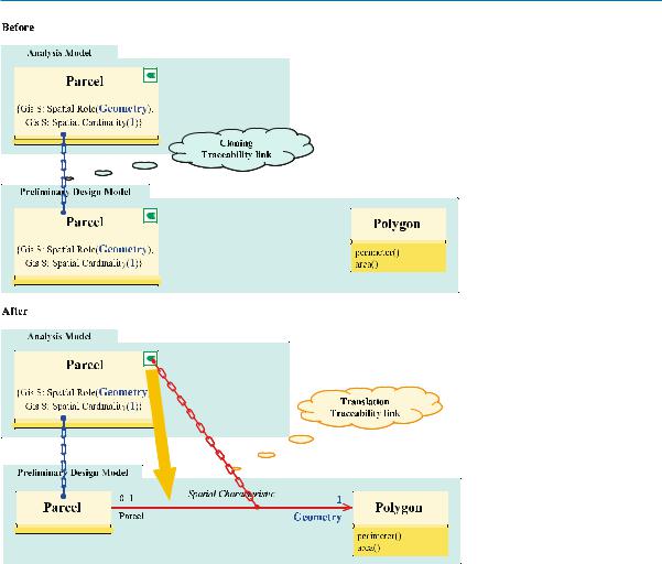
Pictogram Translation Transformation Once the GIS design patterns have been created, the business and the spatial or temporal concepts represented by the pictogram are totally disassociated (Fig. 5). The goal of the Pictogram Translation Transformation is to automatically establish a relationship between the Parcel and Polygon concepts (cf. Fig. 5). This transformation creates an association called Spatial Characteristic.
During the capture of the pictogram, two tagged values are added to the business concept in order to specify the role of the spatial concept ({Gis S: Spatial Role(Geometry)}) and its cardinality ({Gis S: Spatial Cardinality(1)}). By default, this role and this cardinality have the values Geometry and 1, respectively, but the designer can subsequently modify them. In this association, the entity name has been allocated to its role, Parcel in this example, and its cardinalityÕs value is 0..1. Once the association has been created, the stereotype/pictogram and the two tagged values are deleted since this information becomes redundant.
To ensure traceability, the Pictogram Translation Transformation creates a traceability link, called Translation Trace-
1A design pattern systematically names, motivates, and explains a general design that addresses a recurring design problem in objectoriented systems. It describes the problem, the solution, when to apply the solution, and its consequences. It also gives implementation hints and examples. The solution is a general arrangement of objects and classes that solve the problem. The solution is customized and implemented to solve the problem in a particular context [2]
|
|
|
|
|
|
|
|
|
|
|
|
Modeling with Enriched Model Driven Architecture |
703 |
||
|
|
|
|
|
|
|
|
|
|
|
|
|
|
|
|
|
|
|
|
|
|
|
|
|
|
|
|
|
|
|
|
|
|
|
|
|
|
|
|
|
|
|
|
|
|
|
|
|
|
|
|
|
|
|
|
|
|
|
|
|
|
|
|
|
|
|
|
|
|
|
|
|
|
|
|
|
|
|
|
|
|
|
|
|
|
|
|
|
|
|
|
|
|
|
|
|
|
|
|
|
|
|
|
|
|
|
|
|
|
|
|
|
|
|
|
|
|
|
|
|
|
|
|
|
|
|
|
|
|
|
|
|
|
|
|
|
|
|
|
|
|
|
|
|
|
|
|
|
|
|
|
|
|
|
|
|
|
|
|
|
|
|
|
|
|
|
|
|
|
|
|
|
|
|
|
|
|
|
|
|
|
|
|
|
|
|
|
|
|
|
|
|
|
|
|
|
|
|
|
|
|
|
|
|
|
|
|
|
|
|
|
|
|
|
|
|
|
|
|
|
|
|
|
Modeling with Enriched Model Driven Architecture, Figure 2
Principle of the multimodel artifact Software Development Process Model
M
Modeling with Enriched Model Driven Architecture, Figure 3
Example of Cloning Traceability Architecture (to keep the Þgure simple, differing details of the models have been discarded)
Modeling with Enriched Model Driven Architecture, Figure 4 Example of a GIS Design Pattern
704 Modeling with Enriched Model Driven Architecture
Modeling with Enriched Model Driven Architecture, Figure 5 Rule for transforming the stereotype/pictogram couple into an association
ability Link, between the pictogram of the business entity of the analysis model and the Spatial Characteristic association.
SQL Transformations In order to achieve a Full MDA process, SQL Transformations have conceived and implemented. They are applied on the SQL Implementation model. The objective of these transformations is to adapt the SQL Implementation Model after cloning to the SQL code generator of the Case Tool.
The main SQL transformation adds the persistence and primary key attributes (main features of relational database) on UML concepts. Annotated with information speciÞc to SQL, it is possible to generate SQL code to create the spatial database. For that, the SQL code generator available in Case Tool supports is used.
Conclusion
The Software Development Process Approach is a recent contribution to the design and development of spatial
databases. It enriches the MDA by subdividing the PIM level into three levels based on the development process. The reiÞcation of this approach is the Software Development Process Model, a multimodel artifact that meets the previously stated requirements of capitalization. This is so because each of the four modeling levels include concepts that are their very own and independent of those of the preceding level. Without the cloning traceability architecture and the Diffusion Transformation, the functioning and the maintenance of coherence of the Software Development Process Model would become impossible.
Structuring models into SDPM offers a very powerful mutation capability; it becomes very easy to change the hardware or software platform in the course of the development and to improve performance calculations, for example. Such changes can be made at a minimum cost since the analysis, preliminary design and advanced design models constitute the applicationÕs capital, capital that is available and mobilizable at any time. Thus, only the new implementation concepts will require reworking within the new
Modeling with ISO 191xx Standards |
705 |
implementation model. This mutation capability can also be called upon during the applicationÕs life cycle to correct bugs, improve features, mitigate obsolescence of hardware or software platforms, to create new versions of the application, etc.
The two geomatic transformations that have been designed use spatial, temporal and spatio-temporal properties of business concepts annotated with Perceptory pictogrammic language. Some SQL transformations adapt the SQL Implementation Model to the code generator of the Case Tool.
This panoply of transformations automates, for the Þrst time in a full MDA process, the generation of SQL code that allows the Geographical Information SystemÕs database to be reiÞed.
Key Applications
Software Development and Information Technology
The potential beneÞts in terms of productivity, portability, integration and interoperability confer a transversality that should be of interest to the software industry regarding the Software Development Process Approach; more so because this approach can be implemented irrespective of the typology of the software application to be created.
Geographic Information Systems
and Spatial Databases
The Þeld of Geographic Information Systems, including the design of associated spatial or spatio-temporal databases, beneÞt from Enriched Model Driven Architecture.
Future Directions
MDA is an approach that is still young; its broad principles were only enunciated by OMG in 2001. It will surely evolve in the coming years, either at the generalization level Ð the present solution is an example Ð or at the level of transformation languages (QVT, ATL, etc.).
Acknowledgements
The authors thank Professor Yvan BŽdard of the Geomatics Research Center at Laval University and his team for stimulating our thought processes and for contributing to our research.
Cross References
Computer Environments for GIS and CAD
Patterns in Spatio-temporal Data
Recommended Reading
1.BŽdard, Y., LarrivŽe, S., Proulx, M.J., Nadeau, M.: Modeling Geospatial Databases with Plug-ins for Visual Languages: A Pragmatic Approach and the Impacts of 16 Years of Research and Experimentations on Perceptory. In: Proceedings of ER Workshops 2004 CoMoGIS, Shanghai (China), November 2004
2.Gamma, E., Helm, R., Johnson, R., Vlissides, J.: Design patterns Ð Elements of Reusable Object-Oriented Software, 1st edn., Addison Wesley Professional, London (2001)
3.Kleppe, A. (2004): Interview with Anneke Kleppe. Code Generation Network. http://www.codegeneration.net/tiki-read_article. php?articleId=21. date cited: August 2006
4.Kleppe, A., Warmer, J., Bast, W.: MDA Explained: The Model Driven Architecture-Practice and Promise. Addison-Wesley Professional, London (2003)
5.Miller, J., Mukerji, J. (2001): Model Driven Architecture (MDA). OMG. http://www.omg.org/cgi-bin/apps/doc?ormsc/01-07-01. pdf. date cited: September 2004
6.Miller, J., Mukerji, J. (2003): MDA Guide Version 1.0.1. OMG. http://www.omg.org/cgi-bin/doc?omg/03-06-01
7.Miralles, A.: IngŽnierie des mod•les pour les applications environnementales, UniversitŽ Montpellier II, Montpellier, Dissertation (2006)
8.Roques, P., VallŽe, F.: UML en Action Ð De lÕanalyse des besoins ˆ la conception en Java, 2nd edn. Eyrolles, Paris (2002)
|
|
|
M |
|
Modeling with ISO 191xx Standards |
||
|
|||
|
|
||
JEAN BRODEUR1, THIERRY BADARD2
1Natural Resources Canada, Centre for Topographic Information, Sherbrook, QC, Canada
2Centre for Research in Geomatics (CRG), UniversitŽ Laval, Quebec, Canada
Synonyms
Conceptual modeling of geospatial databases; Modeling geospatial databases; Modeling geospatial application database
Definition
Application Schema
ISO19109ÑRules for application schema [1] deÞnes an application schema as a conceptual schema for data required by one or more applications. In the context of geographic information, an application schema documents the content and the structure of geographic databases along with manipulating and processing operations of the application to a level of details that allows developers to set up consistent, maintainable, and unambiguous geographic databases and related applications [2]. As such, an application schema contributes to both the semantics of geographic data and describes the structure of the geographic information in a computer-readable form. It also supports

706 Modeling with ISO 191xx Standards
the use of the geographic data appropriately (i. e., Þtness for use). Typically, an application schema is depicted in a formal conceptual schema language.
Feature Catalog
As in ISO19110ÑMethodology for feature cataloguing [3], a feature catalog presents the abstraction of reality represented in one or more sets of geographic data as a deÞned classiÞcation of phenomena. In the context of geographic information, it is a collection of metadata that provides the semantics and the structure of the objects stored in a geographic database. A feature catalog includes (1) the names and deÞnitions of feature types, (2) their propertiesÕ name and deÞnition including feature attributes, geometry (shapes and speciÞcations, datum, map projection, etc.), temporality (dimensions and speciÞcations, datum, units, resolutions, etc.), operations, and roles, (3) descriptions of attribute values and domains, relationships, constraints, and so on. An application schema may be described in various forms such a text document, a database, a spreadsheet, etc. Typically, a feature catalog is available in electronic form to support interoperability of geographic information. Although both an application schema and a feature catalog address the same content basically, they are complementary in the manner they represent it.
Historical Background
International standardization in the geographic information Þeld has taken place during the last decade. These works have been coordinated by the ISO Technical Committee 211 (ISO/TC 211) [4] and the Open Geospatial Consortium. (OGC) [5]. Standardization in geographic information aims at (1) facilitating and increasing the understanding and use of geographic data, (2) increasing the availability, the access, the integration, the exchange, and the sharing of geographic data (i. e., interoperability of geographic information), (3) enhancing efÞciency when using geographic data, and (4) developing a worldwide orientation of geographic information in support of global problems (ecological, humanitarian, sustainable development, etc.) [4].
Scientific Fundamentals
Interoperability
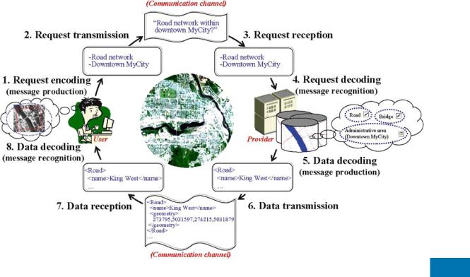
As introduced in [6], interoperability can be seen as the ability of two or more systems or components to exchange information and to use the information that has been exchanged. As such, interoperability adheres to the human communication process (see Fig. 1) where agents (e. g.,
human beings, systems, etc.) interact together at the system, syntactic, schematic, and semantic levels to share information. Each agent has its own conceptual representation of reality and uses it to encode (Fig. 1, steps 1 and 5) and decode messages (e. g., queries and responses about geographic information, Fig. 1, steps 4 and 8), which are transmitted (Fig. 1, steps 2 and 6) to or received (Fig. 1, steps 3 and 7) from another agent through the communication channel. Interoperability happens only when both agents engaged in a communication have the same understanding about the message [7]. Therefore, interoperability agrees to a bidirectional communication process including a feedback mechanism in both directions to control the good reception and understanding of messages.
Accordingly, topics of interest to standardization in geographic information are organization, content, access and technology, and education. Standards cover methods, tools, and data management services (including data deÞnition and description) that are related to interoperability in geographic information including data acquisition, processing, analysis, access, portrayal, and transfer of data between users, systems, and places. They provide a structure for application development related to geographic data and refer to existing standards in information technology and communication (W3C (World Wide Web Consortium), OMG (Object Management Group), IETF (The Internet Engineering Task Force), OASIS (Organization for the Advancement of Structured Information Standards), and so on) when needed. A large number of standards are published as part of the ISO191xx suite of standards (see http://www.iso.ch/iso/en/ stdsdevelopment/tc/tclist/TechnicalCommitteeDetailPage. TechnicalCommitteeDetail?COMMID=4637).
As ISO/TC 211 and OGC share common objectives, a similar program and have complementary approaches, they are now collaborating closely. On the one hand, the OGC wants their speciÞcations to obtain ofÞcial recognition of international standards. On the other hand, ISO/TC 211 wants to beneÞt from OGCÕs work and that OGCÕs speciÞcations comply with ISO 191xx standards. By sharing certain of their resources and developing standardization projects jointly, they aim at reducing the inconsistency between de jure (i. e., ofÞcial, approved by an ofÞcial standardization body like ISO) and de facto or industrial standards (i. e., adopted by users, industry and/or professional sector, because of its popularity and its market share). As an example, ISO 19115ÑMetadata has been adopted by OGC as its Topic 11ÑMetadata, and the speciÞcations of the Web Map Service (WMS) edited by OGC are now an ISO international standard (ISO 19128).
As such, the Þrst part of this chapter concerns the role of conceptual modeling in the Þeld of geographic infor-
Modeling with ISO 191xx Standards |
707 |
Modeling with ISO 191xx Standards, Figure 1 Framework for interoperability
M
mation related to interoperability, while the second concerns the contribution of standards with respect to conceptual modeling in geographic information, before concluding remarks and future considerations are presented.
Geographic Information Modeling
and Interoperability
Typically, organizations have assembled geographic databases for their explicit needs (e. g., censuses, land inventory and management, homeland security, sustainable development, etc.). Over time, a huge amount of geographic information has been accumulated. Considering the high demand for geographic information and the enhancement of web technologies, an increasing number of organizations have begun to disseminate of data they have collected. It is now well known that geographic information is widely available from multiple providers (i. e., governmental agencies, private organizations, etc.) and accessible on the web. Spatial data infrastructures (SDIs) have grown rapidly and, today, support easy access and use of geographic information (e. g., NSDI in the US, CGDI in Canada). Currently, those searching for geographic information can rely on SDIs, which offer a one-stop shop for geographic information in many countries.
However because the variety of available geographic information disseminated and further used without any for-
mal deÞnition, users experience problems in Þnding and obtaining the data that Þt their needs, in analyzing such data, and in making sound decisions in different situations, thus limiting interoperability. Consequently, knowledge about data has become vital.
Knowledge about geographic information is collected in term of metadata. Metadata has been traditionally deÞned as Òdata about dataÓ [8] and constitute a description of captured or modeled data in databases or applications. Basically, metadata refers to the content, the structure, the semantics, the lineage (source, collecting process, etc.), the quality (positional and content accuracy, etc.), the vintage, the resolution, the distribution format, the persons or institutions responsible for the data, etc. Accordingly, conceptual models, conceptual schemas, application schemas, database models, data dictionaries, feature catalogs, and repositories consist of so many approaches to document metadata speciÞcally about the content and definition, the description of the structure, and the semantics of the geographic information. Considering the availability and accessibility to such descriptions of geographic information in a standardized manner, users of geographic information can interpret the information correctly and then identify the suitability of the data for their speciÞc application (i. e., Þtness for use). Therefore, metadata and especially conceptual models are crucial to support interoperability of geographic information.

708 Modeling with ISO 191xx Standards
Moreover in term of database design, it is an excellent practice to deÞne properly the semantics, the geometry, the temporality, and integrity constraints of objects to be included in geographic databases and datasets. Referring to the interoperability framework depicted in the previous section, the content description of geographic databases consists in a fundamental agentÕs knowledge for reasoning and communicating with other agents, since it serves as its ontology. Ontology consists in a formal representation of phenomena with an underlying vocabulary including deÞnitions and axioms that make the intended meaning explicit and describe phenomena and their interrelationships [7]. Database modeling beneÞts greatly from standards. Amongst existing standards, the ISO191xx suite of standards addresses speciÞcally geographic information. The following section describes these standards, which contribute to the development of geographic database models and applications and to the standardized description of geographic information.
Contribution of Standardizations in Geographic Information to Spatiotemporal Modeling
Standards in geographic information contribute at various levels to the modeling of geographic information. The contributions range from the deÞnition of types for data, which support the description of features and attributes, to the deÞnition of standardized methodologies for handling descriptions of concepts of geographic databases or applications.
More speciÞcally, the following standards take part either directly or indirectly to the modeling of geographic information:
¥ISO/TS 19103 Conceptual Schema Language
¥ISO 19107 Spatial Schema
¥ISO 19108 Temporal Schema
¥ISO 19109 Rules for Application Schema
¥ISO 19110 Methodology for Feature Cataloging
¥ISO 19111 Spatial Referencing by Coordinates
¥ISO 19112 Spatial Referencing by Geographic IdentiÞers
¥ISO 19115 Metadata
¥ISO 19135 Procedures for Item Registration
This section is a review of the above standardsÕ contributions to the modeling of spatiotemporal information. Hereafter, the expression Òapplication schemaÓ is used to refer to conceptual model, database model, or any other similar expressions. For a presentation of database modeling levels of abstraction, see the chapter entitled ÒSpatial Database Modeling Pictogrammic Languages.Ó
Conceptual Modeling Language Although ISO/TS 19103 Conceptual Schema Language [9] is intended to
provide rules and guidelines for the use of a conceptual modeling language in ISO 191xx geographic information standards, namely the UniÞed Modeling Language (UML), it also includes deÞnitions of a number of data types which provide a common ground for the representation of attributes and values.
These rules are a help to the harmonization of conceptual models. Basically, ISO/TS 19103 rules follow standard UML [10], but introduce restrictions on the deÞnition of classes, use of multiple inheritance, association role and multiplicity, and multiple class association. For instance, ISO/TS 19103 speciÞes a naming convention to increase readability and consistency: each word of class and relationship names are capitalized without space between them; each word of attribute, relation role, operation, and parameter names are capitalized except the Þrst, without spaces between words. All examples in this chapter follow ISO/TS 19103 rules.
New stereotypes are also introduced: ÒCodeListÓ, ÒLeafÓ, and ÒUnionÓ. ÒCodeListÓ is basically an extensible enumeration of character string values that an attribute can take. As Fig. 2 illustrates, the class EX_Bridge has an attribute structure of the type EX_BridgeStructure, which is a CodeList that enumerates its acceptable values, but is not limited to them. ÒLeafÓ identiÞes packages that have no subpackages. A ÒUnionÓ class is a class that gives to users a choice between multiple alternatives for the description of an attribute, but the attribute must use one, and only one, choice.
In addition, the use of standardized data types when building application schemas for geographic information supports attributesÕ meaning and better understanding of geographic information and, hence, enhances interoperability of geographic information. In ISO/TS 19103, these data types include primitive types, implementation and collection types, and derived types. Primitive types are those that are basic for the representation of elementary values. More speciÞcally, they cover types for the representation of numeric, text, date and time, truth, multiplicities, and elementary enumerations:
¥Numeric: Number, Decimal, Real, Integer, UnlimitedInteger, and Vector
Modeling with ISO 191xx Standards, Figure 2 CodeList example
Modeling with ISO 191xx Standards |
709 |
¥Text: Character, Sequence<Character>, and CharacterString
¥Date and time: Date, Time, and DateTime
¥Truth: Boolean {TRUE =1, FALSE = 0}, Logical {TRUE = 1, FALSE = 0, MAYBE = 0,5}, and Proba-
bility
¥Multiplicity: Multiplicity, MultiplicityRange
¥Elementary enumerations: Sign {+, Ð}, Bit {0, 1}, Digit {zero = 0, one = 1, two 2, three = 3, four = 4, Þve =
5, six = 6, seven = 7, eight = 8, nine = 9}
A collection type is a container of multiple instances of a given type. Collections may have different characteristics with respect to ordering, duplication, and operations. Four types of collection are deÞned: Set, Bag, Sequence, and Dictionary. A Set consists of a deÞnite number of objects of a given type. In a Set, an object appears once and only once (no duplicate are allowed) and objects are not ordered. A Bag is a similar structure to Set, but accepts duplicates. A Sequence, commonly known as a List, is a structure similar to a Bag in which objects are ordered. The CircularSequence is a speciÞc type of Sequence, which does not deÞne any last element making it circular. A Dictionary is an array-like structure that binds a key with a value, as a Òhash tableÓ.
Modeling with ISO 191xx Stan- |
M |
|
dards, Figure 3 |
Basic geo- |
|
metric primitives speciÞed by ISO |
|
|
19107 [11] |
|
|
Derived types refer speciÞcally to units |
of measure. |
|
A generic class UnitOfMeasure is introduced with a number of subclasses, which specify units for the different measures such as length, area, angle, time, etc.
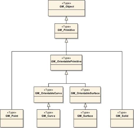
Spatial Schema The representation of spatial characteristics is fundamental in geographic information for the description of geographic feature, either in an application schema or a geographic database. Spatial characteristics encompass the geometry of the feature, its location with respect to a coordinate reference system, and its topological properties with other features. ISO 19107 Spatial Schema [11] deÞnes in detail the geometric and topological characteristics that are needed to describe geographic features spatially. In ISO 19107, geometric characteristics are of three types: primitive (GM_Primitive), aggregate (GM_Aggregate), and complex (GM_Complex). Figure 3 shows ISO 19107 basic geometric primitives: GM_Point, GM_Curve, GM_Surface, and GM_Solid. They provide all components needed to depict the shape and the location of simple geographic features such as buildings, towers, roads, bridges, rivers, etc.
Aggregate geometries (Fig. 4) depict features composed of multiple geometric primitives such as an archipelago,
710 Modeling with ISO 191xx Standards
Modeling with ISO 191xx Standards, Figure 4
Aggregate geometries speciÞed by ISO 19107 [11]
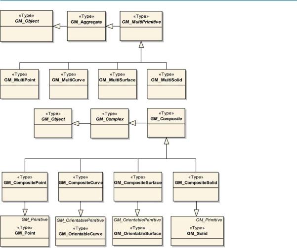
Modeling with ISO 191xx Standards, Figure 5 Complex geometries speciÞed by ISO 19107 [11]
composed of multiple surfaces, or a campus, composed of small (or point like) and large (or surface like) buildings. Accordingly, ISO 19107 deÞnes GM_Aggregate, which is a set of any kind of geometric types (GM_Object); GM_MultiPoint, a set of GM_Points; GM_MultiCurve, a set of GM_OrientableCurves; GM_MultiSurface, a set of GM_OrientableSurfaces; and GM_MultiSolid, a set of GM_Solids.
In some cases, geographic features have a more complicated geometric structure. That is the case for a road or a hydrographical network. Consequently, ISO 19107 has developed geometries for complexes: GM_ Complex, GM_CompositePoint, GM_CompositeCurve, GM_CompositeSurface, GM_CompositeSolid (Fig. 5). They all consist of a set of GM_Primitives, which have disjoint interiors, i. e., the interior of one geometry does not intersect with any other geometry. In a GM_Complex, primitives are joined together only by the way of a common boundary in order to form a unique geometry. For example, a GM_CompositeCurve is made of a set of
GM_OrientableCurves where the Þrst point of each curve, except for the Þrst, corresponds to the last point of the previous one (Fig. 6) and the Þnal GM_CompositeCurve possesses all the properties of a GM_OrientableCurve. Similarly, a GM_CompositePoint behaves as a GM_Point, a GM_CompositeSurface as a GM_OrientableSurface, and a GM_CompositeSolid as a GM_Solid.
The location of all types of geometric primitives, aggregates, and complexes is described with coordinates that are referenced to a coordinate reference systems. This will be discussed in Sect. ÒSpatial ReferencingÓ.
Topological primitives are needed to support complex geometric calculations, such as adjacency, boundary, and network analysis between geometric objects. In ISO 19107, topological primitives are structured similarly to the geometric structure with the deÞnition of topological objects (i. e., TP_Objects). Accordingly, TP_Object is found at the top level of the structure and deÞnes operations that are inherited by all its subordinates. There are two types of TP_Objects: TP_Primitive and TP_Complex (Fig. 7).