

prt%3A978-0-387-35973-1%2F16
.pdfModeling with a UML Profile |
691 |
is the temporal interval between two consecutive occurrences. Train schedules and tidal movements are examples of events with a strong periodic pattern of repetition. The second class of periodicity deals with events that occur regularly, but the occurrences do not necessarily have the same duration nor are they equally spaced in time. For this kind of cycle, the duration of events and the temporal gap between each of them may vary in a stochastic or deterministic manner. The spill of a geyser is an example of a near periodic event. The third class of periodicity deals with events that occur in a more irregular fashion or not regularly enough to be predicted with any degree of certainty. The occurrences of category 5 hurricanes over the Gulf of Mexico are an example of an intermittent phenomenon.
Main Text
Currently, there are many kinds of specialists dealing with or studying phenomena that repeat regularly. Engineers and social scientists, for example, cooperate to synchronize the schedules of the public transportation system with peopleÕs daily routine in urban environments. Environmental, social and Þnancial experts struggle to predict the effect of global warming on seasonal precipitations and, therefore, on the occurrences of ßoods. Biologists and life scientists are working to identify relations between birdsÕ migration cycles and the recurrent occurrences of some human and animalsÕ diseases. Thus, there are many research questions driving the efforts of a wide range of specialists who deal with cyclic phenomena. In the database area, for example, there are needs for conceptual models and formalisms for expressing periodicity and for constructing queries about periodic data. In knowledge representation and temporal reasoning, there are concerns about periodic-based temporal constraints and modeling cyclic temporal relations [1], which are important subjects for scheduling and for constraint satisfaction problems involving cyclic events [2]. In the knowledge discovery and data mining Þeld, there are requests for the support of mining temporal data to discover trends, patterns, and relationships between cyclic recurrent events [3].
The geographic information science research community has had a strong interest in capturing dynamic or time-varying phenomena in geographic space and representing such phenomena in spatio-temporal data models. Most successful models have adopted either spatio-tem- poral extensions of the entity-relationship or object-ori- ented models, or an eventand process-based approach. Whichever model is used to represent the temporal dimension of the phenomena, few studies have focused on happenings that repeat themselves in a cyclic manner.
Cross References
Geographic Dynamics, Visualization And Modeling
Processes and Events
Time Geography
Recommended Reading
1.Hornsby, K., Egenhofer, M., Hayes, P.: Modeling cyclic change. In: Advances in Conceptual Modeling, Proceedings of the ERÕ99 Workshops, Paris, France., Lecture Notes in Computer Science, vol. 1727, pp. 98Ð109. Springer-Verlag, Berlin (1999)
2.Isli, A.: On deciding consistency for CSPs of cyclic time intervals. In: Proceedings of the Fourteenth International Florida ArtiÞcial Intelligence Research Society Conference, Key West, FL, 21Ð23 May 2001
3.Roddick, J.F., Spiliopoulou M.: A bibliography of temporal, spatial and spatio-temporal data mining research. SIGKDD Explor. Newsl. 1, 34Ð38 (1999)
Modeling Geospatial
Application Database
Modeling with ISO 191xx Standards
M
Modeling Geospatial Databases
Modeling with ISO 191xx Standards
Modeling with a UML Profile
JUGURTA LISBOA FILHO1, CIRANO IOCHPE2
1Department of Computer Science/Information Systems, Federal University of Vicosa (UFV), Vicosa, Brazil
2Institute of Computer Science/Information Systems, Federal University of Rio Grande do Sul (UFRGS), Porto Alegre, Brazil
Synonyms
Geographic database conceptual modeling; UniÞed Modeling Language-Geoframe Modeling Language
Definition
A spatial database management system (SDBMS) provides storage structures and basic operations for spatial data manipulation, whereas geographic information systems (GIS) provide the mechanisms for analysis and visualization of geographic data [1]. In this way, geographic databases (GeoDB) are collections of georeferenced spatial data, stored by SDBMS and manipulated by GIS.
GeoDB, as any database, must be designed following the traditional database design methodology that includes the

692 Modeling with a UML Profile
conceptual, logical and physical design phases [2]. To draw up a data schema during the conceptual phase, a conceptual modeling language must be used. A strong tendency exists in computer science to adopt the Unified Modeling Language (UML) [3] as a system modeling standard based on the object-oriented paradigm, and more speciÞcally the UML class diagram for database design. However, for GeoBD design, it is necessary to extend UML with new elements that enable the modeling of spatialÐtemporal characteristics of geographical phenomena. UML is a naturally extensible language, in other words, it has its own constructs allowing its extension. The stereotype concept, one of the UML extension mechanisms, allows the deÞnition of new speciÞc model elements generating a proÞle tailored for a particular problem domain [3]. There are some UML extensions for GeoDB modeling [4,5,6]. To exemplify a spatial UML proÞle, described here is the Spatialtemporal UML-GeoFrame modeling language, which extends the UML, generating a proÞle of stereotypes to support the GeoDB conceptual modeling.
Historical Background
GIS were originated outside the computer science Þeld, unlike most software technologies developed in the last decades such as the operating systems based on windows, DBMS, fourth generation languages, CAD, CAM and CASE tools, OfÞce Automation Systems (OIS), and more recently the World Wide Web (WWW) with the software revolution due to the explosion of internet use.
One of the consequences of this historical origin is that most GIS application designers are their own users, who have the evolutionary approach as their main software developmental methodology, and whose main focus of attention is geospatial data acquisition and analysis. Thus, the old raster-vector debate [7] prevailed for a long time as an important theme in GIS conferences. Consequently, methodologies developed in the software engineering Þeld are frequently not used in GIS application design, causing great losses in the quality of the produced systems and high maintenance costs.
An alternative to reduce these problems is the use of a database design methodology. Consequently, during the 1990s, several extensions of speciÞc conceptual modeling languages for GIS applications were proposed in the literature. Initially these modeling languages were based on the entity-relationship model (ER), proposed by Peter Chen [8] or one of its extensions (e. g., Merise and Enhanced Entity-Relationship, EER). A few modeling languages were based on the semantic data model IFO [9]. At that time, the use of the object-oriented paradigm in system development was becoming more and more popular.
Accordingly, several authors used as their base object-ori- ented design methods, such as OMT [10] and OOA [11], proposing extensions for the modeling of spatiotemporal aspects of geographical phenomena [4,5,6].
With the aim of standardizing the different existent graphic notations and deÞning a basic group of model constructs for software systems, in 1996 three great experts on objectoriented modeling joined their approaches to create the UML [12]. Consequently, by 1999 some UML extensions to GeoDB modeling came out, some of them supported by CASE tools (e. g., Perceptory [4], ArgoCASEGEO [13]). The UML-GeoFrame modeling language [6] is described here, to exemplify a spatial UML proÞle, and show how UML can be naturally extended by its own extension mechanism, named stereotype. Unlike other conceptual modeling languages that seek constructsÕ completeness, so as to consider almost all modeling possibilities of geographical phenomena in different dimensions (descriptive, spatial and temporal), the UML-GeoFrame has as its inspiration the simplicity of the ER model and proposes the smallest possible group of stereotypes to assist the main requirements of GeoDB modeling, but at the same time allowing understanding by nonspecialized users, through a quite simple and instinctive graphic notation.
Scientific Fundamentals
UML-GeoFrame: a Modeling Language for Geographic Databases
A conceptual data modeling language provides a formal base (notational and semantics) for tools and techniques used in data modeling. Data modeling is the abstraction process where only the essential elements of the observed reality are emphasized, the nonessential elements being discarded. The process of conceptual database modeling comprises the description of the possible data content, besides structures and constraints applicable to them. This database description is based on the semantic constructs provided by a conceptual data modeling language.
The UML-GeoFrame, originally presented in [6], is based on a hierarchical class structure that makes up the conceptual GeoFrame framework. The GeoFrame provides the fundamental elements present in any GeoDB, whereas the UML class diagram provides the semantic constructs for a conceptual modeling language. This integration enables GeoDB design in a graphic language easily understandable by the users.
The result of the modeling process is a conceptual data schema that expresses ÒwhatÓ will be stored in the database and not ÒhowÓ the data will be stored. A conceptual data schema becomes therefore an abstraction of the real world that is being modeled (miniworld). Consequently, every
Modeling with a UML Profile |
693 |
element of the reality to be modeled in the conceptual data schema must be stored in the GeoDB. In the same way, every object stored in a GeoDB must have been represented in the conceptual data schema, but this does not often happen.
A GeoDB stores three large data categories: conventional data without geographic reference (e. g., a property owner), geographic phenomena perceived in object view (e. g., cities, roads, parcels), and geographic phenomena perceived in Þeld view (e. g., temperature, soil type, relief). The main UML-GeoFrameÕs contribution consists of providing a construct group that enables the designer to carry out the modeling of the geographic phenomena perceived in Þeld view suitably. The geographic phenomena perceived in the object view and also the conventional objects are modeled in the same way as most existent modeling languages.
Therefore, the UML-GeoFrame uses the same constructs of the UML class diagram, such as classes and subclasses containing attributes and operations, and associations between classes, also enabling the speciÞcation of aggregations and compositions [12].
The GeoFrame Framework
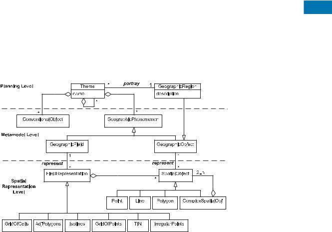
GeoFrame (Fig. 1) is a conceptual framework that provides a basic class diagram to assist the designer on the Þrst steps of the conceptual data modeling of a new GIS application. The mutual use of a UML class diagram and GeoFrame allows the solution of most requirements of GIS application modeling.
The GeoFrame class diagram has three abstraction levels. The Þrst is the planning level, which comprises the GeographicRegion class, whose instances correspond to the application interest areas, and the Theme class, describing the several themes that will portray this area. The metamodel level comprises the most generic classes of the geographic reality, which are divided in two categories, the conventional objects (without spatial representation) and the geographic phenomena, that comprise the geographic phenomena perceived in Þeld view and the geographic phenomena perceived in object view. The third level includes the classes of objects that enable the designer to abstract the type of spatial representation that will be speciÞed for each type of geographic phenomenon, multiple representations being possible.
To exemplify both the UML-GeoFrameÕs constructs and the respective GeoDB design methodology, a hypothetical support system for Brazilian agrarian reform will be used, described as follows.
The Brazilian government is initiating a process of land distribution for families of rural workers, in which nonproductive large landholdings are dispossessed to be divided and distributed. Each family of rural worker receives a par-
cel, size varying according to the country region and also M depending on the available resources in the region, such
as existent cropped areas, pastures, local roads, storage places, housing, or even natural resources availability such as water sources, streams, native vegetation, etc. A GIS application is used to assist in the demarcation of new parcels to be distributed. This distribution is carried out based on criteria that take into consideration, besides the
Modeling with a UML Profile, Figure 1 The GeoFrame framework. TIN Triangular irregular network

694 Modeling with a UML Profile
resources previously mentioned, the relief, soil and vegetation type. Finally, effective environmental laws must be considered, as state laws prohibit the cultivation of agricultural crops in permanent protection areas (hill tops), areas with slope above 45¡ or close to water resources (lakes and rivers).
A short description of the classes belonging to each of the three GeoFrame abstraction levels follows. The way these classes are used during the modeling process is described in UML-GeoFrame Methodology section.
Planning Level This comprises:
¥GeographicRegion: this deÞnes the geographic regions corresponding to the interest areas of a GIS application. For instance, the region corresponding to a large property that will be divided and the region of the municipal district in which the property is located.
¥Theme: each geographic region can be portrayed by several themes. Two examples of themes in the context of the agrarian reform system are Allotment and Environmental Aspects. The themes can be organized in a theme and subtheme hierarchy. Hence, the Environmental Aspects theme could contain, for example, the subthemes Relief, Vegetation and Hydrography.
Metamodel Level This comprises:
¥ConventionalObject: this generalizes the classes of the application without spatial representation. An example could be the worker family class that will receive a parcel from the agrarian reform project.
¥GeographicPhenomenon: this generalizes all application classes that deÞne the geographic phenomena. This class is specialized in the GeographicField and GeographicObject classes.
¥GeographicField: this class is a generalization of all application classes that are perceived in Þeld view. These phenomena are also known as attributes varying in Þeld, for example the classes Relief, Vegetation, Soil Use and Temperature.
¥GeographicObject: this generalizes the application classes perceived in object view, in other words, classes whose instances have a single identity. Examples include Municipal districts, Farms, Parcels, Rivers and roads.
Spatial Representation Level The spatial representation level in the GeoFrame, as part of the conceptual data modeling process that prioritizes ÒwhatÓ rather than ÒhowÓ, allows designers and users to specify the type of spatial representation used to abstract the spatial characteristics of each geographic phenomenon.
The purpose of GeoFrame is not to specify a type of data structure needed to store the spatial datum into the
SDBMS, but only to model the spatial component of a particular geographic phenomenon as the user perceives or abstracts. For instance, in an urban water network application, the Hydrant class is associated with a spatial object of Point type (subclass of SpatialObject). This association only informs that the spatial characteristic of the geographic phenomenon hydrant will be zero-dimensional. However, as it corresponds to a vertex in a network structure, besides the X and Y coordinates, in SDBMS the vertex must be interlinked to other network elements (in order to maintain the topology) through a data structure of type arc-node. Nevertheless, this speciÞcation should only be detailed in the logical design phase of GeoDB. Following this approach, the GeoFrame classes in the spatial representation level are:
¥SpatialObject: generalizes the classes of spatial representation of geographic phenomena in object view, such as Point, Line, Polygon or ComplexSpatialObject, which recurrently consists of two or more spatial objects. This last type of spatial representation is used when the geographic phenomenon presents a composed or complex characteristic (example: an archipelago).
¥FieldRepresentation: the conceptual modeling of spatial representation of geographic phenomena in Þeld view is the major difference of the UML-GeoFrame compared with others. The FieldRepresentation class generalizes the main types of spatial representation used to abstract the spatial characteristic of phenomena in Þeld view, which are: GridOfCells, AdjPolygons, Isolines, GridOfPoints, triangular irregular network (TIN) and IrregularPoints. This speciÞcation only deals with the way the designer/user frequently abstracts the spatial form of geographic Þelds. For example, many users imagine the relief as a geographic phenomenon usually represented by isolines, although other users work with the relief represented by a TIN or a digital elevation model. This basic group of six spatial representation models for phenomena in Þeld view was identiÞed and described in [14] as containing the models most commonly found in GIS. However, new models of spatial representation
for Þelds can be added to GeoFrame.
A project methodology for GeoDB is presented next. GeoFrame consists of a class library that provides the fundamental elements present in any GeoDB. Nevertheless, the basic classes of GeoFrame are represented in the conceptual data schema only in an implicit way, which is done through stereotypes, as shown below.
The UML-GeoFrame Methodology
A methodology for GeoDB modeling based on the UMLGeoFrame is described here; in other words, the steps that
|
|
|
|
|
|
|
|
|
|
|
|
|
|
|
|
|
|
Modeling with a UML Profile |
695 |
|
|
|
|
|
|
|
|
|
|
|
|
|
|
|
|
|
|
|
|
|
|
|
|
|
|
|
|
|
|
|
|
|
|
|
|
|
|
|
|
|
|
|
|
|
|
|
|
|
|
|
|
|
|
|
|
|
|
|
|
|
|
|
|
|
|
|
|
|
|
|
|
|
|
|
|
|
|
|
|
|
|
|
|
|
|
|
|
|
|
|
|
|
|
|
|
|
|
|
|
|
|
|
|
|
|
|
|
|
|
|
|
|
|
|
|
|
|
|
|
|
|
|
|
|
|
|
|
|
|
|
|
|
|
|
|
|
|
|
|
|
|
|
|
|
|
|
|
|
|
|
|
|
|
|
|
|
|
|
|
|
|
|
|
|
|
|
|
|
|
|
|
|
|
|
|
|
|
|
|
|
|
|
|
|
|
|
|
|
|
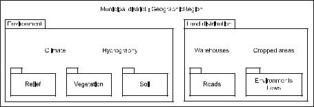
Modeling with a UML Profile, Figure 2 Example of hierarchical theme diagram
should be followed during the GeoDB modeling process and how the GeoFrame elements are integrated with the UML class diagram constructs are presented.
The modeling process based on the UML-GeoFrame comprises Þve steps:
¥Step 1: to identify themes and subthemes for each target region of the application
¥Step 2: to draw a class diagram for each theme speciÞed in step 1, associating classes of different themes, if this is the case
¥Step 3: to model the spatial characteristic of each geographic phenomenon
¥Step 4: to model spatial relationships
¥Step 5: to model temporal aspects
The following subsections present each step in detail.
Step 1: to identify themes and subthemes for each geographic region GIS applications are usually developed focusing on a particular geographic region, it can be an area of great extension such as a country, a state, a municipal district or a large river basin. Maps at small scales are usually manipulated in these applications. On the other hand, numerous applications focus on smaller areas such as a city, neighborhood, farm or small river basins, in which the degree of granularity of the manipulated data is usually much higher, with data usually represented in large-scale maps.
The speciÞcation of various themes that will portray each geographic region, besides allowing a top-down approach to the problem, also aims at facilitating the understanding of large data schema.
The elements identiÞed at this stage are not directly transformed into a SDBMS structure; on the contrary, they are used only in the conceptual modeling phase, enabling the designer to plan and administer the data schema complexity. Theme modeling is done using the UML package construct. Figure 2 shows a possible hierarchical theme diagram for the agrarian reform support system.
Once the diverse themes are deÞned, the designer will be able to focus on a speciÞc theme at a time to carry out data modeling (described in Step 2). For instance,
one can chose Hydrograph and model all the classes of objects pertaining only to this theme. This process simpliÞes modeling and facilitates the understanding of the problem domain by the designer, as well as the communication with users.
Step 2: to draw a class diagram for each theme At |
|
|
this stage, modeling of the data is carried out. For each |
|
|
theme, the several elements of the real world that is being |
|
|
modeled are abstracted. This stage is similar to the tra- |
|
|
ditional database modeling, in which the essential ele- |
|
|
ments of the reality are classiÞed and modeled with the |
|
|
M |
||
UML class diagram constructs. At this stage, based on |
||
the GeoFrame, three classes of objects are identiÞed: con- |
|
|
|
||
ventional, geographic phenomena perceived in object view |
|
|
and phenomena in Þeld view. The existent associations are |
|
|
also modeled among the classes, however, without con- |
|
|
sidering the spatial constraints, which will be discussed in |
|
|
Step 4. |
|
|
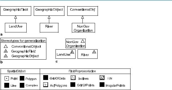
In a modeling process based on a class hierarchy, such as |
|
|
GeoFrame, the application classes should be modeled as |
|
|
subclasses of the GeoFrame classes (Fig. 3a). However, if |
|
|
all the application classes are represented as subclasses of |
|
|
only one of the three classes of the GeoFrame metamod- |
|
|
el level, the data schema will be completely overloaded |
|
|
and difÞcult to read. Thus, three stereotypes were deÞned |
|
|
to replace these generalizationÐspecialization relationships |
|
|
with graphic symbols (Fig. 3b), resulting in the represen- |
|
|
tation shown in Fig. 3c. The idea of replacing relationships |
|
|
with graphic symbols was originally proposed by [15]. The |
|
|
advantage of using these three stereotypes is that in large |
|
|
data schemas, the designers and users can easily identify |
|
|
the application classes according to their main category. |
|
|
Step 3: to model the spatial characteristic of each |
|
|
geographic phenomenon Geographic phenomena differ |
|
|
from conventional objects in that they have spatial prop- |
|
|
erties (attributes and relationships), which are represented |
|
|
in a SDBMS by data structures containing primitive geo- |
|
|
metric object instances (e. g., point, line) or complex ones |
|
|
(e. g., multipoint, multipolygon), whose coordinates repre- |
|
696 Modeling with a UML Profile
Modeling with a UML Profile, Figure 3
GeneralizationÐspecialization stereotypes
Modeling with a UML Profile, Figure 4 Stereotypes for spatial representation
sent points in the geographic space based on a cartographic projection system (e. g., UTM).
During the conceptual modeling stage, the designer should not be stuck on details such ÒhowÓ the geographic phenomena will be stored in SDBMS, but only on abstracting its spatial characteristics. For example, a pole in an electric network has the spatial characteristic of a point, while a lake has the characteristic of extension in the form of a region/polygon. In turn, the relief, which is perceived as a geographic phenomenon in Þeld view, can have its spatial characteristic abstracted by a spatial model of the isoline type. Moreover, the spatial characteristic of a geographic phenomenon can be abstracted from different cartographic representation models, characterizing the existence of multiple representations for the same geographic phenomenon. At the beginning of the 1990s, based on the object-orient- ed paradigm, a number of modeling languages proposed that geographic phenomena were modeled as specialized subclasses of a set of predeÞned classes representing geometric objects. Therefore, the class Street would be modeled as a subclass of the class Line, a class Pole should be modeled as a subclass of the class Point, etc. There was in this approach an incorrect use of the generalizationÐspecialization concept, in which two distinct things were related by an IS-A relationship. That is, a road is not a line and a line is not a road, although a geometric object Line can be related to a geographic object Road to represent its spatial location.
With the UML-GeoFrame, the spatial characteristic of geographic phenomena is not abstracted in the form of spatial attributes, but by means of associations between the classes of geographic phenomena and the classes of spatial
representation. This is speciÞed by the represent association in the GeoFrame (Fig. 1). Again, in order not to overload the data schema, stereotypes are deÞned to replace these associations (Fig. 4).
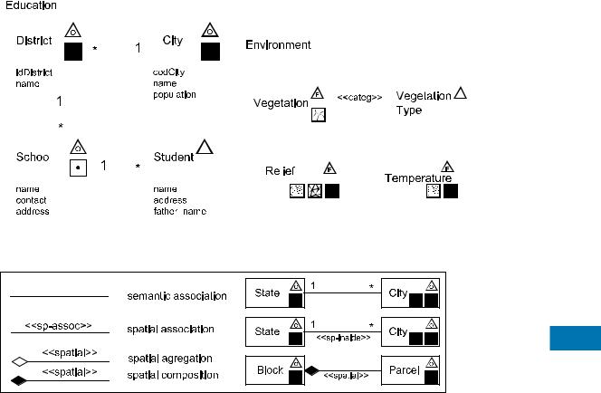
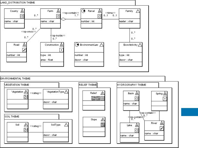
Therefore, in an UML-GeoFrame data schema, each geographic phenomenon class of the application domain will have at least two stereotypes, one for specialization and another for spatial representation. Figure 5 shows an example of a UML-GeoFrame data schema with two packages, one related to the Education theme and the other related to the Environment theme.
As can be seen in this example, the UML-GeoFrame enables a natural, integrated and consistent form of modeling phenomena perceived in Þeld view. In this way, the conceptual data schema contains all the elements of the real world to be stored in the SDBMS and vice versa.
Step 4: to model spatial relationships A relationship modeled on a conceptual data schema semantically implies two facts; the Þrst is that objects of the respective classes can be associated, which allows the user to consult the database based on this relationship, the second is that DBMS will have to guarantee the integrity constraint speciÞed by the multiplicity of this relationship automatically. For example, an one-to-many association (1..* in UML) between the classes City and Farm, means that each farm must be associated at the most to one city, and that each city can be associated to zero or many farms.
In a GIS, this type of relationship can be captured in two ways: spatial and semantic. The spatial way is obtained by spatial operations between two geometric objects, for instance, verifying whether a polygon is inside another
|
|
|
|
|
|
|
|
|
|
|
|
|
|
|
|
|
|
|
|
|
|
|
Modeling with a UML Profile |
697 |
||||
|
|
|
|
|
|
|
|
|
|
|
|
|
|
|
|
|
|
|
|
|
|
|
|
|
|
|
|
|
|
|
|
|
|
|
|
|
|
|
|
|
|
|
|
|
|
|
|
|
|
|
|
|
|
|
|
|
|
|
|
|
|
|
|
|
|
|
|
|
|
|
|
|
|
|
|
|
|
|
|
|
|
|
|
|
|
|
|
|
|
|
|
|
|
|
|
|
|
|
|
|
|
|
|
|
|
|
|
|
|
|
|
|
|
|
|
|
|
|
|
|
|
|
|
|
|
|
|
|
|
|
|
|
|
|
|
|
|
|
|
|
|
|
|
|
|
|
|
|
|
|
|
|
|
|
|
|
|
|
|
|
|
|
|
|
|
|
|
|
|
|
|
|
|
|
|
|
|
|
|
|
|
|
|
|
|
|
|
|
|
|
|
|
|
|
|
|
|
|
|
|
|
|
|
|
|
|
|
|
|
|
|
|
|
|
|
|
|
|
|
|
|
|
|
|
|
|
|
|
|
|
|
|
|
|
|
|
|
|
|
|
|
|
|
|
|
|
|
|
|
|
|
|
|
|
|
|
|
|
|
|
|
|
|
|
|
|
|
|
|
|
|
|
|
|
|
|
|
|
|
|
|
|
|
|
|
|
|
|
|
|
|
|
|
|
|
|
|
|
|
|
|
|
|
|
|
|
|
|
|
|
|
|
|
|
|
|
|
|
|
|
|
|
|
|
|
|
|
|
|
|
|
|
|
|
|
|
|
|
|
|
|
|
|
|
|
|
|
|
|
|
|
|
|
|
|
|
|
|
|
|
|
|
|
|
|
|
|
|
|
|
|
|
|
|
|
|
|
|
|
|
|
|
|
|
|
|
|
|
|
|
|
|
|
|
|
|
|
|
|
|
|
|
|
|
|
|
|
|
|
|
|
|
|
|
|
|
|
|
|
|
|
|
|
|
|
|
|
|
|
|
|
|
|
|
|
|
|
|
|
|
|
|
|
|
|
|
|
|
|
|
|
|
|
|
|
|
|
|
|
|
|
|
|
|
|
|
|
|
|
|
|
|
|
|
|
|
|
|
|
|
|
|
|
|
|
|
|
|
|
|
|
|
|
|
|
|
|
|
|
|
|
|
|
|
|
|
|
|
|
|
|
|
|
|
|
|
|
|
|
|
|
|
|
|
|
|
|
|
|
|
|
|
|
|
|
|
|
|
|
|
|
|
|
|
|
|
|
|
|
|
|
|
|
|
|
|
|
|
|
|
|
|
|
|
|
|
|
|
|
|
|
|
|
|
|
|
|
|
|
Modeling with a UML Profile, Figure 5 Example of a data schema using the UML-GeoFrame notation
M
Modeling with a UML Profile, Figure 6 Stereotypes for spatial relationship
polygon. The semantic way is the traditional database way, where the farm related register contains a Þeld that stores a reference (e. g., foreign-key) for the city that the farm is associated with.
With the UML-GeoFrame the designer can specify the two types of relationships (spatial and semantic), meaning that the SDBMS must guarantee the speciÞed integrity constraint. The semantic relationships correspond to the associations normally speciÞed between classes in the data schema. In this case, referential integrity constraints can be transformed, for example, to foreign-key constraints in a relational DBMS. The integrity constraints of spatial relationships must be implemented in GIS or SDBMS speciÞc procedures.
The possible types of spatial relationships are topological or metric. Engenhofer et al. [16] described a set of types of spatial intersections that can occur between two regions: disjoint, contain, inside, equal, touch, covers, covered by and overlap. This set can be applied to other types of combinations such as point and polygon or line and polygon.
The speciÞcation of spatial associations in the UMLGeoFrame is done with textual stereotypes, i. e., a text between Ò. . . Ó. The text corresponds to the type of spatial constraint one wants to impose, which can be of any type, including the relationships shown in Fig. 6. If there is no textual stereotype, then the association is semantic. Thus, in the logical design phase, the semantic association between State and City (Fig. 6) will be implemented as an attribute in the table City with foreign-key constraint for the table State, whereas the spatial association between State and City will be implemented by a procedure that will apply an inside spatial operation. These examples also show that an instance of City can have multiple spatial representations (point or polygon). Finally, UML constructs of aggregation and composition correspond to WHOLEPART relationships. Figure 6 shows a spatial composition where a Block is modeled as the whole and the Parcels correspond to the parts.
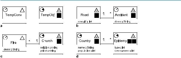
Step 5: to model temporal aspects Numerous geographic phenomena are dynamic, i. e., their properties
698 Modeling with a UML Profile
Modeling with a UML Profile, Figure 7 aÐd Examples of spatiotemporal classes
(descriptive and spatial) undergo changes with time. Although most databases applications reßect only the current state of real-world objects they represent, many applications need to keep the data evolution description as they are changed.
Descriptive, temporal and spatial dimensions are orthogonal. Temporal properties can therefore be deÞned for the three geospace data categories: conventional objects, geographic phenomena perceived in Þeld view and geographic phenomena perceived in object view. In temporal DBMS, two types of time can be deÞned: valid time and transaction time. Rocha et al. [17] presents an extension to the UML-GeoFrame comprising these types of time. However, the enormous possibility of combinations between the different dimensions (e. g., temporal and spatial) led to a highly complex model that was really very little used by GIS users/designers. Thus, only the valid time is presented here.
Valid time is the time instant or time interval when an object of the real world is considered valid. For example, the strike against the World Trade Center took place on September 11, 2001; in turn, the Gulf War occurred in the period between August 1990 and February 1991. Hence, another important factor is the granularity of temporal information. UML-GeoFrame considers three types of time granularity: Date, Time and Timestamp. Specifying the granularity of a temporal attribute is the same as deÞning the domain of a descriptive attribute value (e. g., CHAR or Boolean).
Besides granularity, the designer can specify two types of temporal occurrence: Interval and Instant, which is done using the stereotypes shown in Fig. 7a. An Interval temporal class indicates the need for storage of its evolution, that is, if its properties (descriptive or spatial) are changed, a new version of the same object will be created. In this case, temporal attributes will be inserted to each object version, indicating the initial and Þnal valid time of this object version. In the case of Instant temporality, the class will contain temporal attributes, but new versions will not be created for its objects. The UML-GeoFrame also
allows the speciÞcation of temporal relationships. Following, some examples of modeling of temporal aspects are presented.
Figure 7b shows an association between the Road and Accident classes. The Road class has only spatial aspects, whereas the Accident class is spatiotemporal of the Instant type, characterizing the need for storing the instant (e. g., timestamp) when the accident took place. In the case of Instant temporality, each occurrence (a new accident) creates a new object, and therefore temporal versions of the object will not be generated.
Figure 7c illustrates the Fire class, whose instances are conventional objects with Instant temporality, associated with a spatiotemporal class Church. Each Þre occurrence generates a new object instance that contains temporal data recording Þre valid time (e. g., date or year). In turn, each change in Church properties, with Interval temporality, creates a new version of the same object.
Figure 7d shows two spatiotemporal classes of the Interval type. Each time that a property of the Country class (e. g., population) is changed, a new version of the object country will be created. The same occurs with the class Epidemic, in which both the number of cases and the affected geographic region can be changed.
The UML-GeoFrame methodology establishes the Þve steps described, but they do not need to be executed necessarily in this order. A more experienced designer can model the three aspects (descriptive, spatial and temporal) of a class at the same time. Nevertheless, considering in detail all the aspects involving a GeoDB design is not a trivial task. The objective of the methodology is to assist the designer to work methodologically, in an incremental and organized way.
An Example of the Application for Brazilian Agrarian Reform
Figure 8 shows the Þnal UML-GeoFrame diagram, relative to the hypothetical system of support to agrarian reform, described at the beginning of this entry. This
Modeling with a UML Profile |
699 |
M
Modeling with a UML Profile, Figure 8 Final class diagram for the hypothetical system of support to agrarian reform
schema was depicted using the ArgoCASEGEO CASE tool [13].
In Fig. 8, how the division of the data schema using packages describing the diverse themes facilitates the understanding of the project is shown. This example also shows how natural is modeling, in an integrated way, conventional objects and geographic phenomena in Þeld and object views. Multiple spatial representations, spatial relationships and temporal aspects are also easily speciÞed using the UML-GeoFrame.
Key Applications
The development of a GIS application, however simple it might be, will bring great beneÞts if a conceptual data modeling language is used during the system design phase. The use of these conceptual data modeling languages in
mediumand large-size systems is fundamental. GIS applications have become more and more integrated with other corporative information systems, sharing diverse data bases and running not only as operational control systems (e. g.: cadastres of properties and infrastructure service networks), but as important decision-making support systems.
Future Directions
A CASE tool named ArgoCASEGEO has been developed [13] to assist GeoDB modeling using UML-Geo- Frame. This tool generates logicalÐspatial data schemas for the main data models related to GIS software (e. g., Shape File, Oracle Spatial). One of the innovative characteristics of this tool is to support a catalogue of analysis patterns [18] aimed at enabling the reuse of GeoDB design solutions by different designers.

700 Modeling with Enriched Model Driven Architecture
Acknowledgements
This work has been partially supported by CNPq (Brazilian National Research Council) and Fapemig.
Cross References
Modeling with Pictogrammic Languages
Recommended Reading
1.Shekhar, S., Chawla, S.: Spatial Databases: A Tour. Prentice Hall, New York (2003)
2.Elmasri, R., Navathe, S.B.: Fundamentals of Database Systems, 3rd edn. Addison-Wesley, Reading, MA (2000)
3.OMG Ð Object Management Group (2007) UniÞed Modeling Language. Available at http://www.uml.org
4.BŽdard, Y., LarrivŽe, S., Proulx, M.J., Nadeau, M.: Modeling geospatial databases with plug-ins for visual languages: a pragmatic approach and the impacts of 16 years of research and experimentations on Perceptory. In: Wang, S. et al. (eds.) Conceptual Modeling for GIS (COMOGIS) Workshop ER2004, Shanghai, China, 8Ð12 Nov 2004. Lecture Notes in Computer Science, vol. 3289, pp. 17Ð30. Springer, Berlin (2004)
5.Borges, K.A., Davis, C.D., Laender, A.H.F.: OMT-G: An objectoriented data model for geographic applications. GeoInformatica 5, 221Ð260 (2001)
6.Lisboa Filho, J., Iochpe, C.: Specifying analysis patterns for geographic databases on the basis of a conceptual framework. In: ACM Symposium on Advances in Geographic Information Systems, pp. 9Ð13. Kansas City, 5Ð6 Nov 1999
7.Couclelis, H.: People manipulate objects (but cultivate Þelds): beyond the raster-vector debate in GIS. In: Theories and Methods of Spatial-Temporal Reasoning in Geographic Space. Lecture Notes in Computer Science, vol. 639, pp. 65Ð77. Springer, Berlin (1992)
8.Chen, P.P.S.: The entity-relationship model: towards a uniÞed view of data. ACM Trans. Database Syst. 1, pp. 9Ð36 (1976)
9.Abiteboul, S., Hull, R.: IFO: A formal semantic database model. ACM Trans. Database Syst. 12, 525Ð565 (1987)
10.Rumbaugh, J., Blaha, M., Premerlani, W., Eddy, F., Lorensen, W.: Object-Oriented Modeling and Design. Prentice-Hall, Englewood Cliffs (1991)
11.Coad, P., Yourdon, E.: Object-Oriented Analysis. 2nd edn. Pren- tice-Hall, New York (1991)
12.Booch, G., Jacobson, I., Rumbaugh, J.: The UniÞed Modeling Language User Guide. Addison-Wesley, Reading, MA (1998)
13.Lisboa Filho, J., SodrŽ, V.F., Daltio, J., Rodrigues, M.F., Vilela, V.: A CASE tool for geographic database design supporting analysis patterns. In: Wang S. et al. (eds.) Conceptual Modeling for GIS (COMOGIS) Workshop ER2004, Shanghai, China, 8Ð12 Nov 2004. Lecture Notes in Computer Science, vol. 3289,
17.Rocha, L.V., Edelweiss, N., Iochpe, C.: GeoFrame-T: a temporal conceptual framework for data modeling. In: ACM Symposium on Advances in Geographic Information Systems, Atlanta, 9Ð10 Nov 2001, pp. 124Ð129
18.Lisboa Filho, J., Iochpe, C., Borges, K.A.: Analysis patterns for GIS data schema reuse on urban management applications. CLEI Electron. J. 5, 1Ð15 (2002)
Modeling with Enriched
Model Driven Architecture
ANDRƒ MIRALLES1, THƒRéSE LIBOUREL2
1Centre for Agricultural and Environmental Engineering Research, Earth Observation and GeoInformation
for Environment and Land Development Unit, Montpellier Cedex 5, France
2University of Montpellier II Ð National Center for ScientiÞc Research, Montpellier Laboratory
of Computer Science, Robotics, and Microelectronics, Montpellier Cedex 5, France
Synonyms
MDA; Model driven architecture; Model driven development (MDD); MDE; Model driven engineering
Definition
Model Driven Architecture, formalized in 2001, is a software design approach proposed by the Object Management Group (OMG) with the objective of improving application development. It was conceived of in order to improve the productivity of software development but also to resolve problems of software portability, software integration and software interoperability encountered during development [4].
To achieve this objective, the MDA approach recommends separating the speciÞcation of system functionality from the speciÞcation of the implementation of that functionality on a speciÞc technology platform. For that, the authors of this approach suggest the use of two types of model groups: the Platform Independent Models (PIM) and the Platform SpeciÞc Models (PSM).
PIMs are models providing a description of the structure and functions of a system without technical speciÞcations
pp. 43Ð54. Springer, Berlin (2004)
14.Goodchild, M.F.: Geographical data modeling. Comput. Geosci. of data-processing nature. PSMs are models deÞning how
18, 401Ð408 (2002)
15.BŽdard, Y., Paquette, F.: Extending entity/relationship formalism for spatial information systems. In: AUTO-CARTO 9, Ninth International Symposium on Computer-Assisted Cartography, ASPRS-ACSM, Baltimore, USA, 2Ð7 April 1989
16.Engenhofer, M., Clementini, E., Felice P.: Topological relations between regions with holes. Int. J. Geogr. Inf. Syst. 8, 129Ð144 (1994)
structure and functions of a system are implemented on a speciÞc platform.
In fact, the MDA approach introduces a separation between concepts and speciÞcations needed to develop software. PIMs only contain business concepts. PSMs contain business concepts and also implementation concepts. Since all of the PIM business concepts are includ-