

N68C-S UCC
.pdfSTEP 3: Install Windows® 7 / 7 64-bit / VistaTM / VistaTM 64-bit OS on your system.
Insert the Windows® 7 / 7 64-bit / VistaTM / VistaTM 64-bit optical disk into the optical drive to boot your system, and follow the instruction to install Windows® 7 / 7 64-bit / VistaTM / VistaTM 64-bit OS on your system. When you see “Where do you want to install Windows?” page, please insert the ASRock Support CD into your optical drive, and click the “Load Driver” button on the left on the bottom to load the NVIDIA® RAID drivers. NVIDIA® RAID drivers are in the following path in our Support CD:
.. \ I386 (For Windows® VistaTM OS)
.. \ AMD64 (For Windows® VistaTM 64-bit OS)
After that, please insert Windows® VistaTM / VistaTM 64-bit optical disk into the optical drive again to continue the installation.
NOTE. If you install Windows® 7 / 7 64-bit / VistaTM / VistaTM 64-bit on IDE HDDs and want to manage (create, convert, delete, or rebuild) RAID functions on SATA / SATAII HDDs, you still need to set up “SATA Operation Mode” to [RAID] in BIOS first. Then, please set the RAID configuration by using the Windows RAID installation guide in the following path in the Support CD:
.. \ RAID Installation Guide
NOTE. For Windows® 7 / 7 64-bit users, you do not need to load RAID driver from ASRock support CD. Please use the native driver to install Windows® 7 / 7 64-bit OS, and then install ASRock All-in-1 driver.
2.15 Untied Overclocking Technology
This motherboard supports Untied Overclocking Technology, which means during overclocking, FSB enjoys better margin due to fixed PCI / PCIE buses. Before you enable Untied Overclocking function, please enter “Overclock Mode” option of BIOS setup to set the selection from [Auto] to [CPU, PCIE, Async.]. Therefore, CPU FSB is untied during overclocking, but PCI / PCIE buses are in the fixed mode so that FSB can operate under a more stable overclocking environment.
Please refer to the warning on page 8 for the possible overclocking risk before you apply Untied Overclocking Technology.
3 1

3. BIOS SETUP UTILITY
3.1 Introduction
This section explains how to use the BIOS SETUP UTILITY to configure your system. The SPI Memory on the motherboard stores the BIOS SETUP UTILITY. You may run the BIOS SETUP UTILITY when you start up the computer. Please press <F2> or <Del> during the Power-On-Self-Test (POST) to enter the BIOS SETUP UTILITY, otherwise, POST will continue with its test routines.
If you wish to enter the BIOS SETUP UTILITY after POST, restart the system by pressing <Ctl> + <Alt> + <Delete>, or by pressing the reset button on the system chassis. You may also restart by turning the system off and then back on.
Because the BIOS software is constantly being updated, the following BIOS setup screens and descriptions are for reference purpose only, and they may not exactly match what you see on your screen.
3.1.1 BIOS Menu Bar
The top of the screen has a menu bar with the following selections:
Main |
To set up the system time/date information |
OC Tweaker |
To set up overclocking features |
Advanced |
To set up the advanced BIOS features |
H/W Monitor |
To display current hardware status |
Boot |
To set up the default system device to locate and load the |
|
Operating System |
Security |
To set up the security features |
Exit |
To exit the current screen or the BIOS SETUP UTILITY |
Use < > key or < > key to choose among the selections on the menu bar, and then press <Enter> to get into the sub screen.
3 2
3.1.2Navigation Keys
Please check the following table for the function description of each navigation key.
Navigation Key(s) |
Function Description |
|||||
|
|
|
/ |
|
|
Moves cursor left or right to select Screens |
|
|
|
|
|
||
|
/ |
|
|
Moves cursor up or down to select items |
||
+ / - |
|
To change option for the selected items |
||||
<Enter> |
To bring up the selected screen |
|||||
<F1> |
To display the General Help Screen |
|||||
<F9> |
To load optimal default values for all the settings |
|||||
<F10> |
To save changes and exit the BIOS SETUP UTILITY |
|||||
<ESC> |
To jump to the Exit Screen or exit the current screen |
|||||
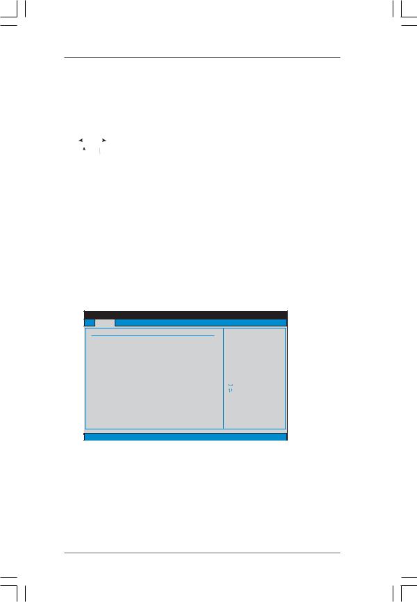
3.2Main Screen
When you enter the BIOS SETUP UTILITY, the Main screen will appear and display the system overview.
N68C-GS UCC
BIOS SETUP UTILITY
Main OC Tweaker Advanced H/W Monitor Boot Security Exit
System Overview
System Time |
[17:00:09] |
System Date |
[Fri 02/12/2010] |
BIOS Version |
: N68C-GS UCC P1.00 |
Processor Type |
: AMD Athlon (tm) 64 X2 Dual Core |
|
Processor 4000+ (64bit) |
Processor Speed |
: 2000MHz |
Microcode Update : 40F32/62 |
|
L1 Cache Size |
: 256KB |
L2 Cache Size |
: 2048KB |
Total Memory |
: 1024MB with 128MB shared memory |
|
Single-Channel Memory Mode |
DDRII_1 |
: 1024MB/266MHz DDR2_533 |
DDRII_2 |
: None |
Use [Enter], [TAB] or [SHIFT-TAB] to select a field.
Use [+] or [-] to configure system Time.
|
Select Screen |
|
Select Item |
+- |
Change Field |
Tab |
Select Field |
F1 |
General Help |
F9 |
Load Defaults |
F10 |
Save and Exit |
ESC |
Exit |
v02.54 (C) Copyright 1985-2005, American Megatrends, Inc.
System Time [Hour:Minute:Second]
Use this item to specify the system time.
System Date [Day Month/Date/Year]
Use this item to specify the system date.
3 3
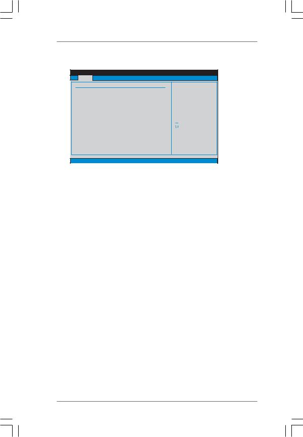
N68C-S UCC
BIOS SETUP UTILITY
Main OC Tweaker Advanced H/W Monitor Boot Security Exit
System Overview
System Time |
[17:00:09] |
System Date |
[Fri 02/12/2010] |
BIOS Version |
: N68C-S UCC P1.00 |
Processor Type |
: AMD Athlon (tm) 64 X2 Dual Core |
|
Processor 4000+ (64bit) |
Processor Speed |
: 2000MHz |
Microcode Update : 40F32/62 |
|
L1 Cache Size |
: 256KB |
L2 Cache Size |
: 2048KB |
Total Memory |
: 1024MB with 128MB shared memory |
|
Single-Channel Memory Mode |
DDRII_1 |
: 1024MB/266MHz DDR2_533 |
DDRII_2 |
: None |
Use [Enter], [TAB] or [SHIFT-TAB] to select a field.
Use [+] or [-] to configure system Time.
|
Select Screen |
|
Select Item |
+- |
Change Field |
Tab |
Select Field |
F1 |
General Help |
F9 |
Load Defaults |
F10 |
Save and Exit |
ESC |
Exit |
v02.54 (C) Copyright 1985-2005, American Megatrends, Inc.
System Time [Hour:Minute:Second]
Use this item to specify the system time.
System Date [Day Month/Date/Year]
Use this item to specify the system date.
3 4
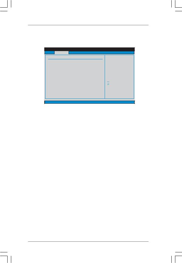
3.3 OC Tweaker Screen
In the OC Tweaker screen, you can set up overclocking features.
BIOS SETUP UTILITY
Main OC Tweaker Advanced H/W Monitor Boot Security Exit
EZ Overclocking
Load Optimized CPU OC Setting |
[Press Enter] |
|
CPU Configuration |
|
|
|
|
|
Overclock Mode |
[Auto] |
|
CPU Frequency (MHz) |
[200] |
|
PCIE Frequency (MHz) |
[100] |
|
Boot Failure Guard |
[Enabled] |
|
[Enabled] |
||
CPU/LDT Spread Spectrum |
||
PCIE Spread Spectrum |
[Enabled] |
|
SATA Spread Spectrum |
[Enabled] |
|
Processor Maximum Frequency |
x10.5 2100 MHZ |
|
Processor Maximum Voltage |
1.2500 V |
|
Multiplier/Voltage Change |
[Auto] |
|
HT Bus Speed |
[Auto] |
|
HT Bus Width |
[Auto] |
Overclocking may cause damage to your CPU and motherboard.
It should be done at your own risk and expense.
|
Select Screen |
|
Select Item |
Enter |
Go to Sub Screen |
F1 |
General Help |
F9 |
Load Defaults |
F10 |
Save and Exit |
ESC |
Exit |
v02.54 (C) Copyright 1985-2005, American Megatrends, Inc.
EZ Overclocking
Load Optimized CPU OC Setting
You can use this option to load the optiomized CPU overclocking setting. Configuration options: [Press Enter], [Default], [5% (2520MHz)] to [40% (3360MHz)]. Please note that overclocking may cause damage to your CPU and motherboard. It should be done at your own risk and expense.
CPU Configuration
Overclock Mode
Use this to select Overclock Mode. The default value is [Auto]. Configuration options: [Auto], [CPU, PCIE, Sync.], [CPU, PCIE, Async.] and [Optimized].
CPU Frequency (MHz)
Use this option to adjust CPU frequency.
PCIE Frequency (MHz)
Use this option to adjust PCIE frequency.
Boot Failure Guard
Enable or disable the feature of Boot Failure Guard.
CPU/LDT Spread Spectrum
This feature will be set to [Enabled] as default. Configuration options: [Disabled] and [Enabled].
PCIE Spread Spectrum
This feature will be set to [Enabled] as default. Configuration options: [Disabled] and [Enabled].
SATA Spread Spectrum
This feature will be set to [Enabled] as default. Configuration options: [Disabled] and [Enabled].
3 5
Processor Maximum Frequency
It will display Processor Maximum Frequency for reference.
North Bridge Maximum Frequency
This option appears only when you adopt Phenom CPU. It will display North Bridge Maximum Frequency for reference.
Processor Maximum Voltage
It will display Processor Maximum Voltage for reference.
Multiplier/Voltage Change
This item is set to [Auto] by default. If it is set to [Manual], you may adjust the value of Processor Frequency and Processor Voltage. However, it is recommended to keep the default value for system stability.
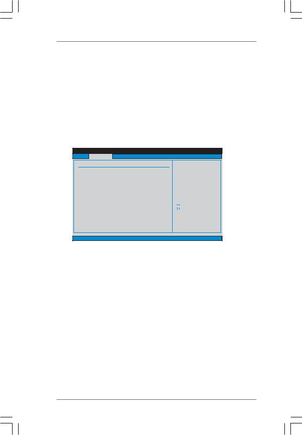
BIOS SETUP UTILITY
Main OC Tweaker Advanced H/W Monitor Boot Security Exit
EZ Overclocking
Load Optimized CPU OC Setting |
[Press Enter] |
||
CPU Configuration |
|
|
|
|
|
|
|
Overclock Mode |
[Auto] |
||
CPU Frequency (MHz) |
[200] |
|
|
PCIE Frequency (MHz) |
[100] |
|
|
Boot Failure Guard |
[Enabled] |
||
[Enabled] |
|||
CPU/LDT Spread Spectrum |
|||
PCIE Spread Spectrum |
[Enabled] |
||
SATA Spread Spectrum |
[Enabled] |
||
Processor Maximum Frequency |
x10.5 2100 MHZ |
||
Processor Maximum Voltage |
1.2500 V |
||
Multiplier/Voltage Change |
[Manual] |
||
Processor Multiplier |
[x10.5 2100 MHz] |
||
Processor Voltage |
[1.2500 V] |
||
Overclocking may cause damage to your CPU and motherboard.
It should be done at your own risk and expense.
|
Select Screen |
|
Select Item |
Enter |
Go to Sub Screen |
F1 |
General Help |
F9 |
Load Defaults |
F10 |
Save and Exit |
ESC |
Exit |
v02.54 (C) Copyright 1985-2005, American Megatrends, Inc.
Processor Frequency
This option appears only when you adopt AM2 CPU. This item will show when “Multiplier/Voltage Change” is set to [Manual]; otherwise, it will be hidden. The range of the value depends on the CPU you adopt on this motherboard. However, for system stability, it is not recommended to adjust the value of this item.
Processor Voltage
This option appears only when you adopt AM2 CPU. This item will show when “Multiplier/Voltage Change” is set to [Manual]; otherwise, it will be hidden. The range of the value depends on the CPU you adopt on this motherboard. However, for safety and system stability, it is not recommended to adjust the value of this item.
CPU Frequency Multiplier
This option appears only when you adopt Phenom CPU. However, for safety and system stability, it is not recommended to adjust the value of this item.
3 6

NB Frequency Multiplier
This option appears only when you adopt Phenom CPU. However, for safety and system stability, it is not recommended to adjust the value of this item.
HT Bus Speed
This feature allows you selecting Hyper-Transport bus speed. Configuration options: [Auto], [x1 200 MHz], [x2 400 MHz], [x3 600 MHz], [x4 800 MHz] and [x5 1000 MHz].
HT Bus Width
This feature allows you selecting Hyper-Transport bus width. Configuration options: [Auto], [8 Bit] and [16 Bit].
ASRock UCC
UCC (Unlock CPU Core) feature simplifies AMD CPU activation. As long as a simple switch of the BIOS option “ASRock UCC”, you can unlock the extra CPU core to enjoy an instant performance boost. When UCC feature is enabled, the dual-core or triple-core CPU will boost to the quad-core CPU, and some CPU, including quad-core CPU, can also increase L3 cache size up to 6MB, which means you can enjoy the upgrade CPU performance with a better price. Please be noted that UCC feature is supported with AM2+ / AM3 CPU only, and in addition, not every AM2+ / AM3 CPU can support this function because some CPU’s hidden core may be malfunctioned.
Memory Configuration Memory Clock
This item can be set by the code using [Auto]. You can set one of the standard values as listed for DDR2 memory modules: [200MHz DDR2_400], [266MHz DDR2_533], [333MHz DDR2_667] and [400MHz DDR2_800]. If you adopt Phenom CPU, there is one more option: [533MHz DDR2_1066]. You can set one of the standard values as listed for DDR3 memory modules: [400MHz DDR3_800], [533MHz DDR3_1066], [667MHz DDR3_1333] and [800MHz DDR3_1600].
DRAM Voltage
Use this to select DRAM voltage. Configuration options: [Auto], [1.794V] to
[2.201V]. The default value is [Auto].
3 7
Memory Timing
|
|
BIOS SETUP UTILITY |
|
|
OC Tweaker |
|
|
|
|
Memory Timing |
|
|
|
|
Memory Controller Mode |
[Unganged] |
|
|
|
Power Down Enable |
|
[Enabled] |
|
|
Bank Interleaving |
|
[Auto] |
|
|
Channel Interleaving |
|
[Hash 1] |
|
|
CAS Latency (CL) |
4 |
[Auto] |
|
|
TRCD |
4 |
[Auto] |
|
|
TRP |
4 |
[Auto] |
|
|
TRAS |
12 |
[Auto] |
|
|
TRTP |
2 |
[Auto] |
|
|
TRRD |
2 |
[Auto] |
|
Select Screen |
TWTR |
2 |
[Auto] |
|
Select Item |
TWR |
4 |
[Auto] |
+- |
Change Option |
TRC |
16 |
[Auto] |
F1 |
General Help |
TRWTWB |
0 |
[Auto] |
F9 |
Load Defaults |
TRWTTO |
4 |
[Auto] |
F10 |
Save and Exit |
TWRRD |
0 |
[Auto] |
ESC |
Exit |
TWRWR |
2 |
[Auto] |
|
|
v02.54 (C) Copyright 1985-2003, American Megatrends, Inc. |
||||
Memory Controller Mode
This option appears only when you adopt Phenom CPU. It allows you to adjust the memory controller mode. Configuration options: [Unganged] and [Ganged]. The default value is [Unganged].
Power Down Enable
Use this item to enable or disable DDR power down mode.
Bank Interleaving
Interleaving allows memory accesses to be spread out over banks on the same node, or accross nodes, decreasing access contention.
Channel Interleaving
This option appears only when you adopt Phenom CPU. It allows you to enable Channel Memory Interleaving. The default value for DDR2 is [Hash 1]. The default value for DDR3 is [Hash 2].
CAS Latency (CL)
Use this item to adjust the means of memory accessing. Configuration options: [Auto], [3CLK], [4CLK], [5CLK] and [6CLK]. The default value is [Auto].
TRCD
Use this to adjust TRCD values. Configuration options: [Auto], [3CLK], [4CLK], [5CLK] and [6CLK]. The default value is [Auto].
TRP
Use this to adjust TRP values. Configuration options: [Auto], [3CLK], [4CLK], [5CLK] and [6CLK]. The default value is [Auto].
TRAS
Use this to adjust TRAS values. Configuration options: [Auto], [5CLK] to [18CLK]. The default value is [Auto].
TRTP
Use this to adjust TRTP values. Configuration options: [Auto], [2-4CLK] and [3-5CLK]. The default value is [Auto].
3 8

TRRD
Use this to adjust TRRD values. Configuration options: [Auto], [2CLK], [3CLK], [4CLK] and [5CLK]. The default value is [Auto].
TWTR
Use this to adjust TWTR values. Configuration options: [Auto], [1CLK], [2CLK] and [3CLK]. The default value is [Auto].
TWR
Use this to adjust TWR values. Configuration options: [Auto], [3CLK], [4CLK], [5CLK] and [6CLK]. The default value is [Auto].
TRC
Use this to adjust TRC values. Configuration options: [11CLK] to [26CLK]. The default value is [Auto].
TRWTWB
Use this to adjust TRWTWB values. Configuration options: [3CLK] to [10CLK]. The default value is [Auto].
TRWTTO
This option appears only when you adopt AM2 CPU. Use this to adjust TRWTTD values. Configuration options: [Auto], [2CLK], [3CLK], [4CLK], [5CLK], [6CLK], [7CLK], [8CLK] and [9CLK]. The default value is [Auto].
TWRRD
This option appears only when you adopt AM2 CPU. Use this to adjust TWRRD values. Configuration options: [Auto], [0CLK], [1CLK], [2CLK] and [3CLK]. The default value is [Auto].
TWRWR
This option appears only when you adopt AM2 CPU. Use this to adjust TWRWR values. Configuration options: [Auto], [1CLK], [2CLK] and [3CLK]. The default value is [Auto].
TRDRD
This option appears only when you adopt AM2 CPU. Use this to adjust TRWTTD values. Configuration options: [Auto], [2CLK], [3CLK], [4CLK] and [5CLK]. The default value is [Auto].
TRFC0
Use this to adjust TRFC0 values. Configuration options: [Auto], [75ns], [105ns], [127.5ns], [195ns] and [327.5ns]. The default value is [Auto].
TRFC1
Use this to adjust TRFC1 values. Configuration options: [Auto], [75ns], [105ns], [127.5ns], [195ns] and [327.5ns]. The default value is [Auto].
MA Timing
Use this to adjust values for MA timing. Configuration options: [Auto], [2T], [1T]. The default value is [Auto].
3 9

CHA ADDR/CMD Delay
Use this to adjust values for CHA ADDR/CMD Delay feature. Configuration options: [Auto], [No Delay], [1/64CLK] to [31/64CLK]. The default value is [Auto].
CHA ADDR/CMD Setup
Use this to adjust values for CHA ADDR/CMD Setup feature. Configuration options: [Auto], [1/2CLK] and [1CLK]. The default value is [Auto].
CHA CS/ODT Delay
Use this to adjust values for CHA CS/ODT Delay feature. Configuration options: [Auto], [No Delay], [1/64CLK] to [31/64CLK]. The default value is [Auto].
CHA CS/ODT Setup
Use this to adjust values for CHB CS/ODT Setup feature. Configuration options: [Auto], [1/2CLK] and [1CLK]. The default value is [Auto].
CHB ADDR/CMD Delay
Use this to adjust values for CHB ADDR/CMD Delay feature. Configuration options: [Auto], [No Delay], [1/64CLK] to [31/64CLK]. The default value is [Auto].
CHB ADDR/CMD Setup
Use this to adjust values for CHB ADDR/CMD Setup feature. Configuration options: [Auto], [1/2CLK] and [1CLK]. The default value is [Auto].
CHB CS/ODT Delay
Use this to adjust values for CHB CS/ODT Delay feature. Configuration options: [Auto], [No Delay], [1/64CLK] to [31/64CLK]. The default value is [Auto].
CHB CS/ODT Setup
Use this to adjust values for CHB CS/ODT Setup feature. Configuration options: [Auto], [1/2CLK] and [1CLK]. The default value is [Auto].
CHA CKE Drive
Use this to adjust values for CHA CKE Drive. Configuration options: [Auto], [1.00x], [1.25x], [1.50x] and [2.00x]. The default value is [Auto].
CHA CS/ODT Drive
Use this to adjust values for CHA CS/ODT Drive. Configuration options: [Auto], [1.00x], [1.25x], [1.50x] and [2.00x]. The default value is [Auto].
CHA ADDR/CMD Drive
Use this to adjust values for CHA ADDR/CMD Drive. Configuration options: [Auto], [1.00x], [1.25x], [1.50x] and [2.00x]. The default value is [Auto].
CHA CLK Drive
Use this to adjust values for CHA CLK Drive. Configuration options: [Auto], [0.75x], [1.00x], [1.25x] and [1.50x]. The default value is [Auto].
4 0