

N68C-S UCC
.pdfafter you update the BIOS. If you need to clear the CMOS when you just finish updating the BIOS, you must boot up the system first, and then shut it down before you do the clear-CMOS action.
2.7 Onboard Headers and Connectors
Onboard headers and connectors are NOT jumpers. Do NOT place jumper caps over these headers and connectors. Placing jumper caps over the headers and connectors will cause permanent damage of the motherboard!
•
Floppy Connector
(33-pin FLOPPY1)
(see p.11No. 24) |
Pin1 |
FLOPPY1 |
|
the red-striped side to Pin1
Note: Make sure the red-striped side of the cable is plugged into Pin1 side of the connector.
Primary IDE connector (Blue)
(39-pin IDE1, see p.11 No. 9)
|
PIN1 |
IDE1 |
|
|
|
connect the blue end |
|
connect the black end |
to the motherboard |
|
to the IDE devices |
80-conductor ATA 66/100/133 cable
Note: Please refer to the instruction of your IDE device vendor for the details.
Serial ATAII Connectors
(SATAII_1 (PORT 0.0): |
SATAII_1 |
SATAII_3 |
||
see p.11,No. 10) |
(PORT 0.0) |
(PORT 1.0) |
||
(SATAII_2 (PORT 0.1): |
|
|
|
|
|
|
|
|
|
see p.11,No. 13) |
|
|
|
|
|
|
|
|
|
(SATAII_3 (PORT 1.0): |
|
SATAII_2 |
SATAII_4 |
|
see p.11,No. 11) |
|
(PORT 0.1) |
(PORT 1.1) |
|
(SATAII_4 (PORT 1.1): |
|
|
|
|
see p.11,No. 12) |
|
|
|
|
These four Serial ATAII (SATAII) connectors support SATAII or SATA hard disk for internal storage devices. The current SATAII interface allows up to 3.0 Gb/s data transfer rate.
Serial ATA (SATA) |
Either end of the SATA data cable |
Data Cable |
can be connected to the SATA / |
(Optional) |
SATAII hard disk or the SATAII |
|
connector on the motherboard. |
2 1
USB 2.0 Headers |
|
P-9 |
|
|
|
USB_PWR |
|
(9-pin USB8_9) |
|
P+9 |
|
|
GND |
||
|
|
|
DUMMY |
(see p.11 No. 16) |
1 |
|
|
|
|
|
|
|
|
GND |
|
|
|
P+8 |
|
|
|
P-8 |
|
|
|
USB_PWR |
|
(9-pin USB6_7) |
|
USB_PWR |
|
|
P-7 |
|
|
(see p.11 No. 17) |
|
P+7 |
|
|
GND |
||
|
|
|
DUMMY |
|
1 |
|
|
|
|
GND |
|
|
|
P+6 |
|
|
|
P-6 |
|
|
|
USB_PWR |
|
(9-pin USB4_5) |
|
USB_PWR |
|
|
P+5 |
|
|
|
|
P-5 |
|
(see p.11 No. 18) |
|
GND |
|
|
|
DUMMY |
|
|
1 |
|
|
|
|
GND |
|
|
|
P+4 |
|
|
|
P-4 |
|
|
|
USB_PWR |
|
Print Port Header |
AFD# |
|
|
(25-pin LPT1) |
ERROR# |
|
|
PINIT# |
GND |
||
|
SLIN# |
||
|
|
|
|
(see p.11 No. 23) |
|
|
|
|
1 |
|
|
|
|
SPD7 |
|
|
|
SPD6 |
ACK# |
|
|
SPD5 |
BUSY |
|
|
SPD4 |
PE |
|
SPD3 |
SLCT |
|
|
SPD2 |
|
|
|
SPD1 |
|
|
|
SPD0 |
|
|
|
STB# |
|
|
Internal Audio Connectors |
|
|
|
(4-pin CD1) |
|
|
CD1 |
(CD1: see p.11 No. 26) |
|
CD NG NG CD |
|
|
|
L- D D R- |
|
Front Panel Audio Header |
GND |
|
|
|
|
|
|
|
|
PRESENCE# |
|
(9-pin HD_AUDIO1) |
|
MIC_RET |
|
|
|
OUT_RET |
|
(see p.11, No. 27) |
|
|
|
|
|
1 |
|
|
|
|
OUT2_L |
|
|
|
J_SENSE |
|
|
OUT2_R |
|
|
|
MIC2_R |
|
|
|
MIC2_L |
|
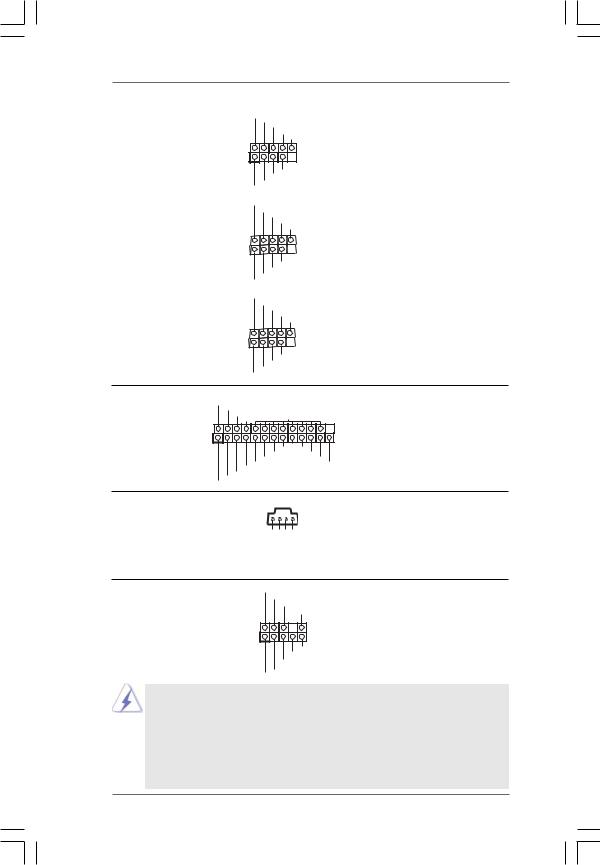
Besides four default USB 2.0 ports on the I/O panel, there are three USB 2.0 headers on this motherboard. Each USB 2.0 header can support two USB 2.0 ports.
This is an interface for print port cable that allows convenient connection of printer devices.
This connector allows you to receive stereo audio input from sound sources such as a CD-ROM, DVD-ROM, TV tuner card, or MPEG card.
This is an interface for the front panel audio cable that allows convenient connection and control of audio devices.
1.High Definition Audio supports Jack Sensing, but the panel wire on the chassis must support HDA to function correctly. Please follow the instruction in our manual and chassis manual to install your system.
2.If you use AC’97 audio panel, please install it to the front panel audio header as below:
A.Connect Mic_IN (MIC) to MIC2_L.
B.Connect Audio_R (RIN) to OUT2_R and Audio_L (LIN) to OUT2_L.
2 2
C.Connect Ground (GND) to Ground (GND).
D.MIC_RET and OUT_RET are for HD audio panel only. You don’t need to connect them for AC’97 audio panel.
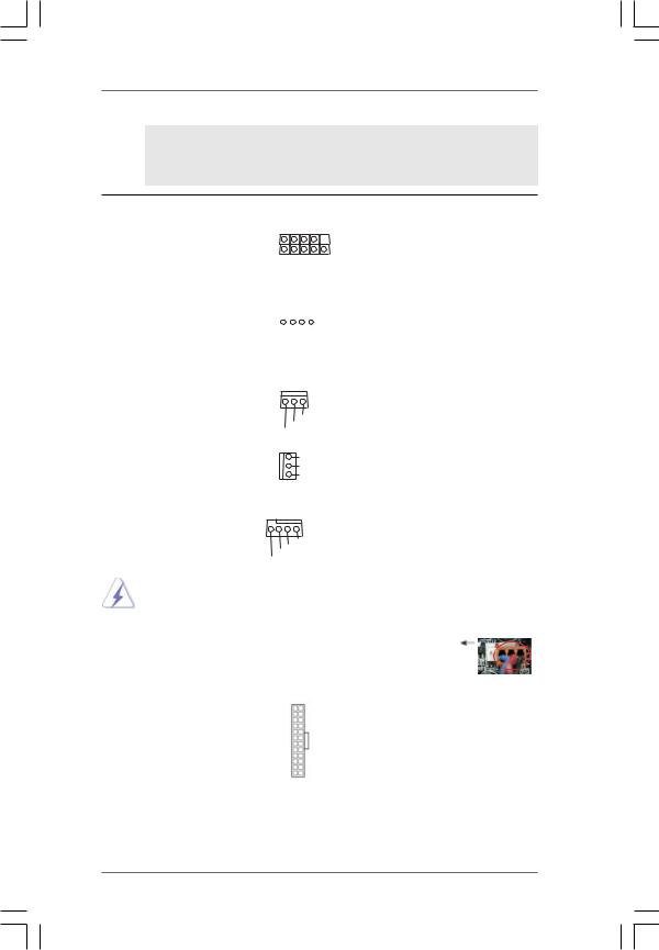
System Panel Header |
|
|
PLED+ |
This header accommodates |
|||||||
|
|
|
|
PLED- |
|||||||
(9-pin PANEL1) |
|
|
|
|
|
PWRBTN# |
several system front panel |
||||
|
|
|
|
|
|
|
GND |
||||
(see p.11 No. 20) |
1 |
|
|
|
|
|
|
|
DUMMY |
functions. |
|
|
|
|
|
|
|
|
|||||
|
|
|
|
|
|
|
|||||
|
|
|
|
|
|
|
|
|
|
||
|
|
|
|
|
|
|
|
|
|
|
|
|
|
|
|
|
|
|
|
|
|
|
|
|
|
|
|
|
|
|
|
|
RESET# |
|
|
|
|
|
|
|
|
|
GND |
|
|||
|
|
|
|
|
|
HDLED- |
|
||||
|
|
|
|
HDLED+ |
|
||||||
|
|
|
|
|
|
|
|
|
|
||
Chassis Speaker Header |
Please connect the chassis |
||||||||||
(4-pin SPEAKER 1) |
1 |
|
|
|
|
|
|
|
|
speaker to this header. |
|
|
|
|
|
|
|
|
SPEAKER |
||||
(see p.11 No. 19) |
|
|
|
|
|
DUMMY |
|
||||
|
|
|
|
DUMMY |
|
||||||
|
|
|
|
+5V |
|
||||||
|
|
|
|
|
|
|
|
|
|
||
Chassis and Power Fan Connectors |
Please connect the fan cables |
||||||||||
(3-pin CHA_FAN1) |
|
|
|
|
|
|
|
|
|
to the fan connectors and |
|
(see p.11 No. 21) |
|
|
|
|
|
GND |
match the black wire to the |
||||
|
|
|
|
+12V |
|||||||
|
|
|
|
|
|
|
|||||
|
|
|
|
CHA_FAN_SPEED |
ground pin. |
||||||
|
|
|
|
|
|
|
|
|
|
|
|
(3-pin PWR_FAN1) |
|
|
|
|
|
GND |
|
||||
|
|
|
|
+12V |
|
||||||
(see p.11 No. 25) |
|
|
|
|
|
||||||
|
|
|
|
PWR_FAN_SPEED |
|
||||||
|
|
|
|
|
|
|
|||||
CPU Fan Connector |
4 3 2 1 |
|
|
|
|
Please connect the CPU fan |
|||||
(4-pin CPU_FAN1) |
|
|
|
|
|
|
|
|
|
cable to this connector and |
|
(see p.11 No. 2) |
|
|
|
|
GND |
match the black wire to the |
|||||
|
+12V |
||||||||||
|
|
CPU_FAN_SPEED |
ground pin. |
||||||||
|
|
FAN_SPEED_CONTROL |
|||||||||
|
|
|
|
|
|
|
|
|
|
|
|
|
|
|
|
|
|
|
|
|
|
|
|
|
|
|
|
|
|
|
|
|
|
|
|
ATX Power Connector |
12 |
24 |
Please connect an ATX power |
(24-pin ATXPWR1) |
|
|
supply to this connector. |
(see p.11 No. 8) |
|
|
|
|
1 |
13 |
|
2 3
|
Though this motherboard provides 24-pin ATX power connector, |
12 |
|
24 |
||
|
|
|||||
|
it can still work if you adopt a traditional 20-pin ATX power supply. |
|
|
|
||
|
To use the 20-pin ATX power supply, please plug your power |
|
|
|
||
|
supply along with Pin 1 and Pin 13. |
|
|
|
||
|
|
|
20-PinATX Power Supply Installation |
1 |
13 |
|
|
|
|
|
|||
|
|
|
|
|
|
|
|
|
|
|
|
|
|
ATX 12V Power Connector |
|
Please note that it is necessary |
||||
(4-pin ATX12V1) |
|
to connect a power supply with |
||||
|
||||||
(see p.11 No. 3) |
|
ATX 12V plug to this connector. |
||||
|
||||||
|
|
|
Failing to do so will cause power |
|||
|
|
|
up failure. |
|
|
|
2 4
2.8 SATAII Hard Disk Setup Guide
Before installing SATAII hard disk to your computer, please carefully read below SATAII hard disk setup guide. Some default setting of SATAII hard disks may not be at SATAII mode, which operate with the best performance. In order to enable SATAII function, please follow the below instruction with different vendors to correctly adjust your SATAII hard disk to SATAII mode in advance; otherwise, your SATAII hard disk may fail to run at SATAII mode.
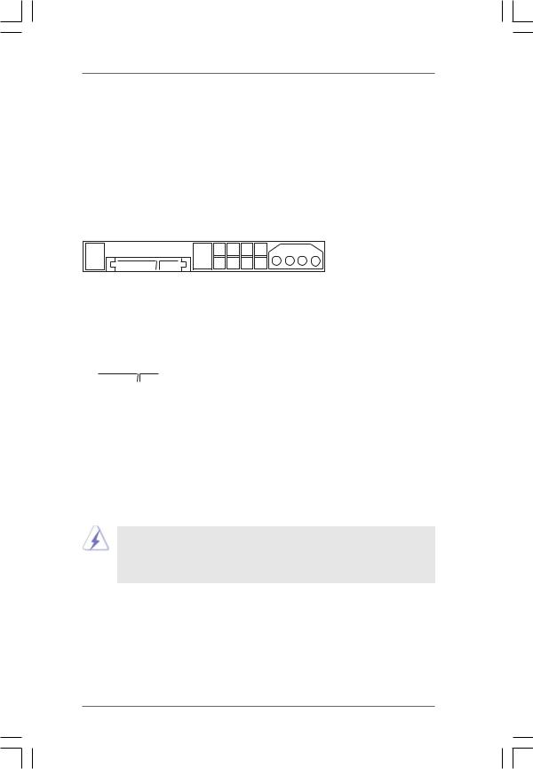
Western Digital
7 |
5 |
3 |
1 |
8 |
6 |
4 |
2 |
If pin 5 and pin 6 are shorted, SATA 1.5Gb/s will be enabled.
On the other hand, if you want to enable SATAII 3.0Gb/s, please remove the jumpers from pin 5 and pin 6.
SAMSUNG
|
|
|
|
|
|
|
|
|
|
|
|
|
|
|
|
|
|
|
|
|
|
|
|
|
|
|
7 |
5 |
3 |
1 |
|
|
|
|
|
|
|
|
|
|
|
|
|
|
|
|
|
|
|
|
|
|
|
|
|
|
|
|
|
|
8 |
6 |
4 |
2 |
|
|
|
If pin 3 and pin 4 are shorted, SATA 1.5Gb/s will be enabled.
On the other hand, if you want to enable SATAII 3.0Gb/s, please remove the jumpers from pin 3 and pin 4.
HITACHI
Please use the Feature Tool, a DOS-bootable tool, for changing various ATA features. Please visit HITACHI’s website for details: http://www.hitachigst.com/hdd/support/download.htm
The above examples are just for your reference. For different SATAII hard disk products of different vendors, the jumper pin setting methods may not be the same. Please visit the vendors’ website for the updates.
2 5
2.9 Serial ATA (SATA) / Serial ATAII (SATAII) Hard Disks Installation
This motherboard adopts NVIDIA® GeForce 7025 / nForce 630a chipset that supports Serial ATA (SATA) / Serial ATAII (SATAII) hard disks and RAID functions. You may install SATA / SATAII hard disks on this motherboard for internal storage devices. This section will guide you to install the SATA / SATAII hard disks.
STEP 1: Install the SATA / SATAII hard disks into the drive bays of your chassis. STEP 2: Connect the SATA power cable to the SATA / SATAII hard disk.
STEP 3: Connect one end of the SATA data cable to the motherboard’s SATAII connector.
STEP 4: Connect the other end of the SATA data cable to the SATA / SATAII hard disk.
2.10 Hot Plug and Hot Swap Functions for SATA / SATAII HDDs
This motherboard supports Hot Plug and Hot Swap functions for SATA / SATAII Devices.
NOTE
What is Hot Plug Function?
If the SATA / SATAII HDDs are NOT set for RAID configuration, it is called “Hot Plug” for the action to insert and remove the SATA / SATAII HDDs while the system is still power-on and in working condition. However, please note that it cannot perform Hot Plug if the OS has been installed into the SATA / SATAII HDD.
What is Hot Swap Function?
If SATA / SATAII HDDs are built as RAID1 or RAID 5 then it is called “Hot Swap” for the action to insert and remove the SATA / SATAII HDDs while the system is still power-on and in working condition.
2 6
2.11 SATA / SATAII HDD Hot Plug Feature and Operation Guide
This motherboard supports Hot Plug feature for SATA / SATAII HDD in RAID mode. Please read below operation guide of SATA / SATAII HDD Hot Plug feature carefully. Before you process the SATA / SATAII HDD Hot Plug, please check below cable accessories from the motherboard gift box pack.
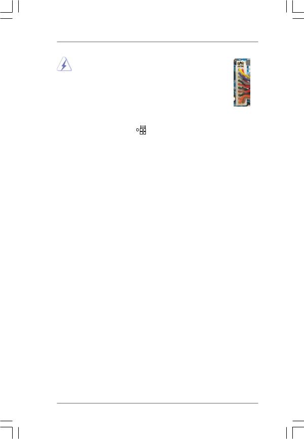
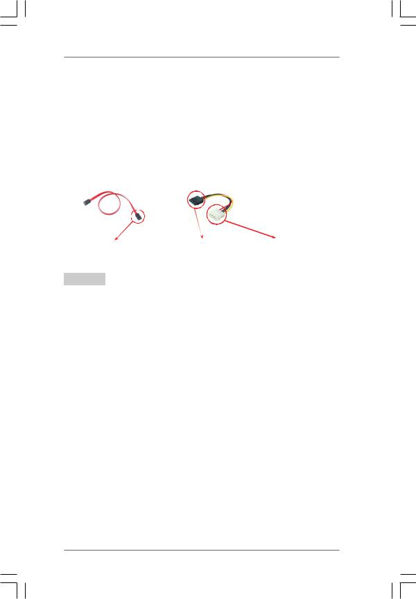
A.7-pin SATA data cable
B.SATA power cable with SATA 15-pin power connector interface
A. SATA data cable (Red) |
B. SATA power cable |
||||
|
|
|
|
|
|
|
|
|
|
|
|
SATA7-pin |
|
The SATA 15-pin power |
|
1x4-pin conventional |
connector |
|
connector (Black) connect |
|
power connector (White) |
|
|
to SATA / SATAII HDD |
|
connect to power supply |
|
|
|||
|
|
|
|
|
Caution
1.Without SATA 15-pin power connector interface, the SATA / SATAII Hot Plug cannot be processed.
2.Even some SATA / SATAII HDDs provide both SATA 15-pin power connector and IDE 1x4-pin conventional power connector interfaces, the IDE 1x4-pin conventional power connector interface is definitely not able to support Hot Plug and will cause the HDD damage and data loss.
Points of attention, before you process the Hot Plug:
1.Below operation procedure is designed only for our motherboard, which supports SATA / SATAII HDD Hot Plug.
*The SATA / SATAII Hot Plug feature might not be supported by the chipset because of its limitation, the SATA / SATAII Hot Plug support information of our motherboard is indicated in the product spec on our website: www.asrock.com
2.Make sure your SATA / SATAII HDD can support Hot Plug function from your dealer or HDD user manual. The SATA / SATAII HDD, which cannot support Hot Plug function, will be damaged under the Hot Plug operation.
3.Please make sure the SATA / SATAII driver is installed into system properly. The latest SATA / SATAII driver is available on our support website: www.asrock.com
4.Make sure to use the SATA power cable & data cable, which are from our motherboard package.
5.Please follow below instructions step by step to reduce the risk of HDD crash or data loss.
2 7
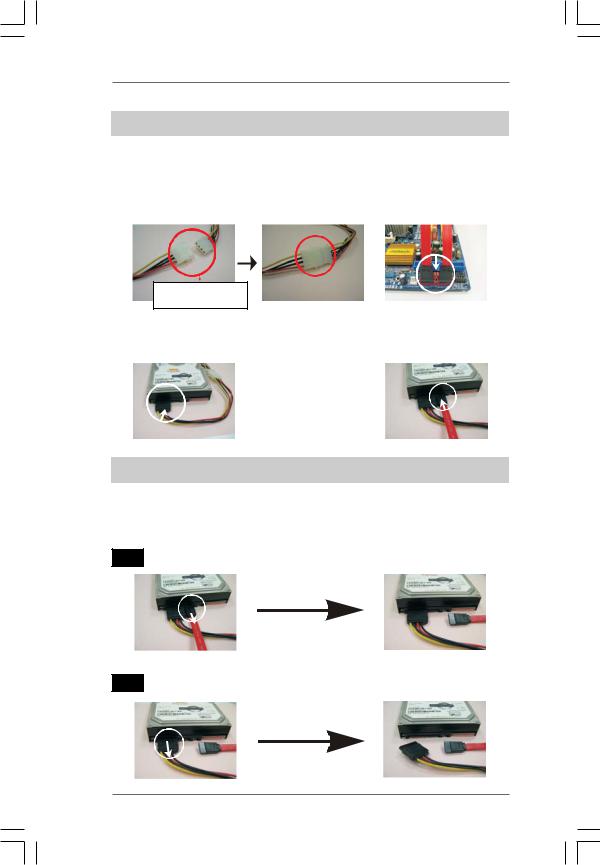
How to Hot Plug a SATA / SATAII HDD:
Points of attention, before you process the Hot Plug:
Please do follow below instruction sequence to process the Hot Plug, improper procedure will cause the SATA / SATAII HDD damage and data loss.
Step 1 |
Please connect SATA power cable 1x4-pin end |
Step 2 |
Connect SATA data cable to |
|
(White) to the power supply 1x4-pin cable. |
|
the motherboard’s SATAII connector. |
SATApower cable 1x4-pin power connector (White)
Step 3 |
Connect SATA 15-pin power cable connector |
Step 4 |
Connect SATA data cable to |
|
(Black) end to SATA / SATAII HDD. |
|
the SATA / SATAII HDD. |
How to Hot Unplug a SATA / SATAII HDD:
Points of attention, before you process the Hot Unplug:
Please do follow below instruction sequence to process the Hot Unplug, improper procedure will cause the SATA / SATAII HDD damage and data loss.
Step 1 Unplug SATA data cable from SATA / SATAII HDD side.
Step 2 Unplug SATA 15-pin power cable connector (Black) from SATA / SATAII HDD side.
2 8

2.12 Driver Installation Guide
To install the drivers to your system, please insert the support CD to your optical drive first. Then, the drivers compatible to your system can be auto-detected and listed on the support CD driver page. Please follow the order from up to bottom side to install those required drivers. Therefore, the drivers you install can work properly.
2.13 Installing Windows® 7 / 7 64-bit / VistaTM /
VistaTM 64-bit / XP / XP 64-bit Without RAID Functions
If you just want to install Windows® 7 / 7 64-bit / VistaTM / VistaTM 64-bit / XP / XP 64bit on your SATA / SATAII HDDs without RAID functions, you don’t have to make a SATA / SATAII driver diskette. Besides, there is no need for you to change the BIOS setting. You can start to install Windows® 7 / 7 64-bit / VistaTM / VistaTM 64-bit / XP / XP 64-bit on your system directly.
2.14 Installing Windows® 7 / 7 64-bit / VistaTM /
VistaTM 64-bit / XP / XP 64-bit With RAID Functions
If you want to install Windows® 7 / 7 64-bit / VistaTM / VistaTM 64-bit / XP / XP 64-bit OS on your SATA / SATAII HDDs with RAID functions, please follow below procedures according to the OS you install.
2.14.1Installing Windows® XP / XP 64-bit With RAID
Functions
If you want to install Windows® XP or Windows® XP 64-bit on your SATA / SATAII HDDs with RAID functions, please follow below steps.
STEP 1: Set Up BIOS.
A.Enter BIOS SETUP UTILITY  Advanced screen
  Storage Configuration.
B.Set the “SATA Operation Mode” option to [IDE].
STEP 2: Make a SATA / SATAII Driver Diskette.
A.Insert the ASRock Support CD into your optical drive to boot your system.
B.During POST at the beginning of system boot-up, press <F11> key, and then a window for boot devices selection appears. Please select CD-ROM as the boot device.
C.When you see the message on the screen, “Generate Serial ATA driver diskette [YN]?”, press <Y>.
2 9
D.Then you will see these messages,
Please insert a blank formatted diskette into floppy
drive A:
press any key to start
Please insert a floppy diskette into the floppy drive, and press any key.
E.The system will start to format the floppy diskette and copy SATA / SATAII drivers into the floppy diskette.
STEP 3: Set Up BIOS.
A.Enter BIOS SETUP UTILITY  Advanced screen
  Storage Configuration.
B.Set the “SATA Operation Mode” option to [RAID].
STEP 4: Use “RAID Installation Guide” to set RAID configuration.
Before you start to configure RAID function, you need to check the RAID installation guide in the Support CD for proper configuration. Please refer to the BIOS RAID installation guide in the following path in the Support CD:
.. \ RAID Installation Guide
STEP 5: Install Windows® XP / XP 64-bit OS on your system.
You can start to install Windows® XP / Windows® XP 64-bit OS on your system. At the beginning of Windows® setup, press F6 to install a third-party RAID driver. When prompted, insert the SATA / SATAII driver diskette containing the NVIDIA® RAID driver. After reading the floppy disk, the driver will be presented. Select the driver to install according to the mode you choose and the OS you install.
NOTE. If you install Windows® XP / Windows® XP 64-bit on IDE HDDs and want to manage (create, convert, delete, or rebuild) RAID functions on SATA / SATAII HDDs, you still need to set up “SATA Operation Mode” to [RAID] in BIOS first. Then, please set the RAID configuration by using the Windows RAID installation guide in the following path in the Support CD:
.. \ RAID Installation Guide
2.14.2Installing Windows® 7 / 7 64-bit / VistaTM /
VistaTM 64-bit With RAID Functions
If you want to install Windows® 7 / 7 64-bit / VistaTM / VistaTM 64-bit on your SATA / SATAII HDDs with RAID functions, please follow below steps.
STEP 1: Set Up BIOS.
A.Enter BIOS SETUP UTILITY Advanced screen
  Storage Configuration.
B.Set the “SATA Operation Mode” option to [RAID].
STEP 2: Use “RAID Installation Guide” to set RAID configuration.
Before you start to configure RAID function, you need to check the RAID installation guide in the Support CD for proper configuration. Please refer to the BIOS RAID installation guide part of the document in the following path in the Support CD:
.. \ RAID Installation Guide
3 0