

- •Release History
- •Contents
- •List of Figures
- •List of Tables
- •1 TMS320TCI6616 Features
- •1.1 KeyStone Architecture
- •1.2 Device Description
- •1.3 Functional Block Diagram
- •2 Device Overview
- •2.1 Device Characteristics
- •2.2 CPU (DSP Core) Description
- •2.3 Memory Map Summary
- •2.4 Boot Sequence
- •2.5 Boot Modes Supported and PLL Settings
- •2.5.1 Boot Device Field
- •2.5.2 Device Configuration Field
- •2.5.2.1 No Boot Device Configuration
- •2.5.2.2 Serial Rapid I/O Boot Device Configuration
- •2.5.2.3 Ethernet (SGMII) Boot Device Configuration
- •2.5.2.4 PCI Boot Device Configuration
- •2.5.2.5 I2C Boot Device Configuration
- •2.5.2.6 SPI Boot Device Configuration
- •2.5.2.7 HyperLink Boot Device Configuration
- •2.5.3 PLL Settings
- •2.6 Second-Level Bootloaders
- •2.7 Terminals
- •2.8 Terminal Functions
- •2.9 Development
- •2.9.1 Development Support
- •2.9.2 Device Support
- •Related Documentation from Texas Instruments
- •3 Device Configuration
- •3.1 Device Configuration at Device Reset
- •3.2 Peripheral Selection After Device Reset
- •3.3 Device State Control Registers
- •3.3.1 Device Status (DEVSTAT) Register
- •3.3.2 Device Configuration Register
- •3.3.3 JTAG ID (JTAGID) Register Description
- •3.3.4 Kicker Mechanism (KICK0 and KICK1) Register
- •3.3.5 LRESETNMI PIN Status (LRSTNMIPINSTAT) Register
- •3.3.6 LRESETNMI PIN Status Clear (LRSTNMIPINSTAT_CLR) Register
- •3.3.7 Reset Status (RESET_STAT) Register
- •3.3.8 Reset Status Clear (RESET_STAT_CLR) Register
- •3.3.9 Boot Complete (BOOTCOMPLETE) Register
- •3.3.10 Power State Control (PWRSTATECTL) Register
- •3.3.11 NMI Even Generation to CorePac (NMIGRx) Register
- •3.3.12 IPC Generation (IPCGRx) Registers
- •3.3.13 IPC Acknowledgement (IPCARx) Registers
- •3.3.14 IPC Generation Host (IPCGRH) Register
- •3.3.15 IPC Acknowledgement Host (IPCARH) Register
- •3.3.16 Timer Input Selection Register (TINPSEL)
- •3.3.17 Timer Output Selection Register (TOUTPSEL)
- •3.3.18 Reset Mux (RSTMUXx) Register
- •3.4 Pullup/Pulldown Resistors
- •4 System Interconnect
- •4.1 Internal Buses, Bridges, and Switch Fabrics
- •4.2 Data Switch Fabric Connections
- •4.3 Configuration Switch Fabric
- •4.4 Bus Priorities
- •5 C66x CorePac
- •5.1 Memory Architecture
- •5.1.1 L1P Memory
- •5.1.2 L1D Memory
- •5.1.3 L2 Memory
- •5.1.4 MSM SRAM
- •5.1.5 L3 Memory
- •5.2 Memory Protection
- •5.3 Bandwidth Management
- •5.4 Power-Down Control
- •5.5 CorePac Resets
- •5.6 CorePac Revision
- •5.7 C66x CorePac Register Descriptions
- •6 Device Operating Conditions
- •6.1 Absolute Maximum Ratings
- •6.2 Recommended Operating Conditions
- •6.3 Electrical Characteristics
- •7 TMS320TCI6616 Peripheral Information and Electrical Specifications
- •7.1 Parameter Information
- •7.1.1 1.8-V Signal Transition Levels
- •7.1.2 Timing Parameters and Board Routing Analysis
- •7.2 Recommended Clock and Control Signal Transition Behavior
- •7.3 Power Supplies
- •7.3.1 Power-Up Sequencing
- •7.3.1.1 Core-Before-IO Power Sequencing
- •7.3.1.2 IO-Before-Core Power Sequencing
- •7.3.1.3 Prolonged Resets
- •7.3.2 Power-Down Sequence
- •7.3.3 Power Supply Decoupling and Bulk Capacitors
- •7.3.4 SmartReflex
- •7.4 Enhanced Direct Memory Access (EDMA3) Controller
- •7.4.1 EDMA3 Device-Specific Information
- •7.4.2 EDMA3 Channel Synchronization Events
- •7.5 Interrupts
- •7.5.1 Interrupt Sources and Interrupt Controller
- •7.5.2 INTC Registers
- •7.5.2.1 INTC0 Register Map
- •7.5.2.2 INTC1 Register Map
- •7.5.2.3 INTC2 Register Map
- •7.5.3 Inter-Processor Register Map
- •7.5.4 NMI and LRESET
- •7.5.5 External Interrupts Electrical Data/Timing
- •7.6 Memory Protection Unit (MPU)
- •7.6.1 MPU Registers
- •7.6.1.1 MPU Register Map
- •7.6.1.2 Device-Specific MPU Registers
- •7.6.2 MPU Programmable Range Registers
- •7.6.2.1 Programmable Range n Start Address Register (PROGn_MPSAR)
- •7.6.2.2 Programmable Range n - End Address Register (PROGn_MPEAR)
- •7.6.2.3 Programmable Range n Memory Protection Page Attribute Register (PROGn_MPPA)
- •7.7 Reset Controller
- •7.7.1 Power-on Reset
- •7.7.2 Hard Reset
- •7.7.3 Soft Reset
- •7.7.4 Local Reset
- •7.7.5 Reset Priority
- •7.7.6 Reset Controller Register
- •7.7.7 Reset Electrical Data/Timing
- •7.8 Main PLL and the PLL Controller
- •7.8.1 Main PLL Controller Device-Specific Information
- •7.8.1.1 Internal Clocks and Maximum Operating Frequencies
- •7.8.1.2 Main PLL Controller Operating Modes
- •7.8.1.3 Main PLL Stabilization, Lock, and Reset Times
- •7.8.2 PLL Controller Memory Map
- •7.8.2.1 PLL Secondary Control Register (SECCTL)
- •7.8.2.2 PLL Controller Divider Register (PLLDIV2, PLLDIV5, PLLDIV8)
- •7.8.2.3 PLL Controller Clock Align Control Register (ALNCTL)
- •7.8.2.4 PLLDIV Divider Ratio Change Status Register (DCHANGE)
- •7.8.2.5 SYSCLK Status Register (SYSTAT)
- •7.8.2.6 Reset Type Status Register (RSTYPE)
- •7.8.2.7 Reset Control Register (RSTCTRL)
- •7.8.2.8 Reset Configuration Register (RSTCFG)
- •7.8.2.9 Reset Isolation Register (RSISO)
- •7.8.3 Main PLL Control Registers
- •7.8.4 Main PLL Controller/SRIO/HyperLink/PCIe Clock Input Electrical Data/Timing
- •7.9.1 DDR3 PLL Control Register
- •7.9.2 DDR3 PLL Device-Specific Information
- •7.9.3 DDR3 PLL Input Clock Electrical Data/Timing
- •7.10 PASS PLL
- •7.10.1 PASS PLL Control Register
- •7.10.2 PASS PLL Device-Specific Information
- •7.10.3 PASS PLL Input Clock Electrical Data/Timing
- •7.11 DDR3 Memory Controller
- •7.11.1 DDR3 Memory Controller Device-Specific Information
- •7.11.2 DDR3 Memory Controller Electrical Data/Timing
- •7.12 I2C Peripheral
- •7.12.1 I2C Device-Specific Information
- •7.12.2 I2C Peripheral Register Description(s)
- •7.12.3 I2C Electrical Data/Timing
- •7.12.3.1 Inter-Integrated Circuits (I2C) Timing
- •7.13 SPI Peripheral
- •7.13.1 SPI Electrical Data/Timing
- •7.13.1.1 SPI Timing
- •7.14 HyperLink Peripheral
- •7.15 UART Peripheral
- •7.16 PCIe Peripheral
- •7.17 Packet Accelerator
- •7.18 Security Accelerator
- •7.19 Ethernet MAC (EMAC)
- •7.20 Management Data Input/Output (MDIO)
- •7.21 Timers
- •7.21.1 Timers Device-Specific Information
- •7.21.2 Timers Electrical Data/Timing
- •7.22 Rake Search Accelerator (RSA)
- •7.23 Enhanced Viterbi-Decoder Coprocessor (VCP2)
- •7.24 Third-Generation Turbo Decoder Coprocessor (TCP3d)
- •7.25 Turbo Encoder Coprocessor (TCP3e)
- •7.26 Serial RapidIO (SRIO) Port
- •7.27 General-Purpose Input/Output (GPIO)
- •7.27.1 GPIO Device-Specific Information
- •7.27.2 GPIO Electrical Data/Timing
- •7.28 Semaphore2
- •7.29 Antenna Interface Subsystem 2
- •7.32 FFTC
- •7.33 Emulation Features and Capability
- •7.33.1 Advanced Event Triggering (AET)
- •7.33.2 Trace
- •7.33.2.1 Trace Electrical Data/Timing
- •7.33.3 IEEE 1149.1 JTAG
- •7.33.3.1 IEEE 1149.1 JTAG Compatibility Statement
- •7.33.3.2 JTAG Electrical Data/Timing
- •8 Mechanical Data
- •8.1 Packaging Information
- •8.2 Package CYP

INFORMATION ADVANCE
TMS320TCI6616
Communications Infrastructure KeyStone SoC
SPRS624A—January 2011 |
www.ti.com |
|
7.7 Reset Controller
The reset controller detects the different type of resets supported on the TMS320TCI6616 device and manages the distribution of those resets throughout the device.
The device has the following types of resets:
•Power-on Reset
•Hard Reset
•Soft Reset
•Local Reset
Table 7-42 explains further the types of reset, the reset initiator, and the effects of each reset on the device. For more information on the effects of each reset on the PLL controllers and their clocks, see Section 7.7.7 ‘‘Reset Electrical Data/Timing’’ on page 151.
Table 7-42 |
Reset Types |
|
||||||
|
|
|
|
|
|
|
|
|
Type |
|
|
|
|
|
Initiator |
Effect(s) |
|
|
|
|
|
pin |
Resets the entire chip including the test and emulation logic. The device configuration pins are |
|||
Power-on Reset |
|
|
POR |
|||||
|
|
|
|
|
|
|
latched only during Power-on Reset. |
|
|
|
RESETFULL pin |
||||||
|
|
|
|
|||||
|
|
|
|
|
|
|
|
Hard Reset resets everything except for test, emulation logic and reset isolation modules. This |
|
|
|
|
pin |
reset is also different from Power-on Reset in that the PLLCTL assumes power and clocks are stable |
|||
|
|
|
RESET |
|||||
|
|
|
PLLCTL (1) register (RSCTRL) |
when Hard Reset is asserted. The device configurations pins are not re-latched. |
||||
Hard Reset |
|
|
Emulation initiated reset is always a Hard Reset. |
|||||
|
|
Watchdog Timers |
||||||
|
|
|
By default these initiators are configured as Hard reset, but can be configured (Except Emulation) |
|||||
|
|
|
Emulation |
|||||
|
|
|
as Soft reset in the RSCFG register of PLLCTL. Contents of DDR3 SDRAM memory can be retained |
|||||
|
|
|
|
|
|
|
|
during a Hard Reset if the SDRAM is placed in self-refresh mode. |
|
|
|
|
|
|
|
|
|
|
|
|
|
|
|
|
|
Soft Reset will behave like Hard Reset except that PCIe MMRs and DDR3 EMIF MMRs contents are |
|
|
|
RESET pin |
|||||
|
|
|
retained. |
|||||
|
|
|
|
|
|
|
|
|
Soft Reset |
|
|
PLLCTL register (RSCTRL) |
By default these initiators are configured as Hard reset, but can be configured as Soft reset in the |
||||
|
|
|
Watchdog Timers |
RSCFG register of PLLCTL. Contents of DDR3 SDRAM memory can be retained during a Soft Reset if |
||||
|
|
|
the SDRAM is placed in self-refresh mode. |
|||||
|
|
|
|
|
|
|
|
|
|
|
|
|
|
|
|||
Local Reset |
|
|
|
|
|
pin |
Resets the CorePac, without destroying clock alignment or memory contents. The device |
|
LRESET |
||||||||
|
|
|
Watchdog Timer timeout |
configuration pins are not re-latched. |
||||
|
|
|
|
|||||
|
|
|
LPSC MMRs |
|
||||
|
|
|
||||||
End of Table 7-42 |
|
|||||||
|
|
|
|
|
|
|
|
|
1 All masters in the device have access to the PLLCTL registers.
7.7.1 Power-on Reset
Power-on reset is used to reset the entire device, including the test and emulation logic.
Power-on reset is initiated by the following
1.POR pin
2.RESETFULL pin
During power-up, the POR pin must be asserted (driven low) until the power supplies have reached their normal operating conditions. A RESETFULL pin is also provided to allow the on-board host to reset the entire device including the reset isolated logic. The assumption is that, device is already powered up and hence unlike POR, RESETFULL pin will be driven by the on-board host control other than the power good circuitry. For power-on reset, the Main PLL controller comes up in bypass mode and the PLL is not enabled. Other resets do not affect the state of the PLL or the dividers in the PLL controller.
148 |
Copyright 2011 Texas Instruments Incorporated |
TMS320TCI6616
Communications Infrastructure KeyStone SoC
www.ti.com |
SPRS624A—January 2011 |
|
The following sequence must be followed during a power-on reset:
1.Wait for all power supplies to reach normal operating conditions while keeping the POR pin asserted (driven low). While POR is asserted, all pins except RESETSTAT will be set to high-impedance. After the POR pin is de-asserted (driven high), all Z group pins, low group pins, and high group pins are set to their reset state and will remain at their reset state until otherwise configured by their respective peripheral. All peripherals that are power managed, are disabled after a Power-on Reset and must be enabled through the Device State Control registers (for more details, see Section Table 3-2 ‘‘Device State Control Registers’’ on page 61).
2.Clocks are reset, and they are propagated throughout the chip to reset any logic that was using reset synchronously. All logic is now reset and RESETSTAT will be driven low indicating that the device is in reset.
3.POR must be held active until all supplies on the board are stable then for at least an additional time for the Chip level PLLs to lock.
4.The POR pin can now be de-asserted. Reset sampled pin values are latched at this point. The Chip level PLLs is taken out of reset and begins its locking sequence, and all power-on device initialization also begins.
5.After device initialization is complete, the RESETSTAT pin is de-asserted (driven high). By this time, DDR3 PLL has already completed its locking sequence and is outputting a valid clock. The system clocks of both PLL controllers are allowed to finish their current cycles and then paused for 10 cycles of their respective system reference clocks. After the pause, the system clocks are restarted at their default divide by settings.
6.The device is now out of reset and device execution begins as dictated by the selected boot mode.
Note—To most of the device, reset is de-asserted only when the POR and RESET pins are both de-asserted (driven high). Therefore, in the sequence described above, if the RESET pin is held low past the low period of the POR pin, most of the device will remain in reset. The RESET pin should not be tied together with the POR pin.
7.7.2 Hard Reset
A Hard reset will reset everything on the device except the PLLs, test, emulation logic and reset isolation modules.
POR should also remain de-asserted during this time.
Hard reset is initiated by the following
•RESET pin
•RSCTRL register in PLLCTL
•Watchdog Timer
•Emulation
All the above initiators by default are configured to act as Hard reset. Except Emulation all the other 3 initiators can be configured as Soft resets in the RSCFG register in PLLCTL.
The following sequence must be followed during a Hard reset:
1.The RESET pin is pulled active low for a minimum of 24 CLKIN1 cycles. During this time the RESET signal is able to propagate to all modules (except those specifically mentioned above). All I/O are Hi-Z for modules affected by RESET, to prevent off-chip contention during the warm reset.
2.Once all logic is reset, RESETSTAT is driven active to denote that the device is in reset.
3.The RESET pin can now be released. A minimal device initialization begins to occur. Note that configuration pins are not re-latched and clocking is unaffected within the device.
4.After device initialization is complete, the RESETSTAT pin is de-asserted (driven high).
Note—The POR pin should be held inactive (high) throughout the warm reset sequence. Otherwise, if POR is activated (brought low), the minimum POR pulse width must be met. The RESET pin should not be tied together with the POR pin.
ADVANCE INFORMATION
Copyright 2011 Texas Instruments Incorporated |
149 |

INFORMATION ADVANCE
TMS320TCI6616
Communications Infrastructure KeyStone SoC
SPRS624A—January 2011 |
www.ti.com |
|
7.7.3 Soft Reset
A soft reset will behave like a hard reset except that the PCIe MMRs and DDR3 EMIF MMRs contents are retained. POR should also remain de-asserted during this time.
Soft reset is initiated by the following
•RESET pin
•RSCTRL register in PLLCTL
•Watchdog Timer
•Emulation
All the above initiators by default are configured to act as Hard reset. Except Emulation all the other 3 initiators can be configured as Soft resets in the RSCFG register in PLLCTL.
In the case of a soft reset, the clock logic or the power control logic of the peripherals are not affected, and, therefore, the enabled/disabled state of the peripherals is not affected. The following external memory contents are maintained during a soft reset:
•DDR3 MMRs: The DDR3 Memory Controller registers are not reset. In addition, the DDR3 SDRAM memory content is retained if the user places the DDR3 SDRAM in self-refresh mode before invoking the soft reset.
•PCIe MMRs: The contents of the memory connected to the EMIFA are retained. The EMIFA registers are not reset.
During a soft reset, the following happens:
1.The RESETSTAT pin goes low to indicate an internal reset is being generated. The reset is allowed to propagate through the system. Internal system clocks are not affected. PLLs also remain locked.
2.After device initialization is complete, the RESETSTAT pin is deasserted (driven high). In addition, the PLL controllers pause their system clocks for about 8 cycles.
At this point:
›The state of the peripherals before the soft reset is not changed.
›The I/O pins are controlled as dictated by the DEVSTAT register.
›The DDR3 MMRs and PCIe MMRs retain their previous values. Only the DDR3 Memory Controller and PCIe state machines are reset by the soft reset.
›The PLL controllers are operating in the mode prior to soft reset. System clocks are unaffected.
The boot sequence is started after the system clocks are restarted. Since the configuration pins are not latched with a System Reset, the previous values, as shown in the DEVSTAT register, are used to select the boot mode.
150 |
Copyright 2011 Texas Instruments Incorporated |
TMS320TCI6616
Communications Infrastructure KeyStone SoC
www.ti.com |
SPRS624A—January 2011 |
|
7.7.4 Local Reset
The local reset can be used to reset a particular CorePac without resetting any other chip components.
Local reset is initiated by the following (for more details see the Phase Locked Loop (PLL) Controller for KeyStone Devices User Guide in ‘‘Related Documentation from Texas Instruments’’ on page 59):
•LRESET pin
•Watchdog Timer should cause one of the below based on the setting of the CORESEL[2:0] and RSTCFG registers in the PLL controller. See ‘‘Reset Configuration Register (RSTCFG)’’ on page 163 and ‘‘INTC Registers’’ on page 124.
–Local Reset
–NMI
–NMI followed by a time delay and then a local reset for the core selected
–Hard Reset by requesting reset via PLLCTL
•LPSC MMRs
7.7.5 Reset Priority
If any of the above reset sources occur simultaneously, the PLLCTL processes only the highest priority reset request. The reset request priorities are as follows (high to low):
•Power-on reset
•Hard/Soft reset
7.7.6 Reset Controller Register
The reset controller register are part of the PLLCTL MMRs. All TCI6616 device-specific MMRs are covered in Section 7.8.2 ‘‘PLL Controller Memory Map’’ on page 157. For more details on these registers and how to program them, see the Phase Locked Loop (PLL) Controller for KeyStone Devices User Guide in ‘‘Related Documentation from Texas Instruments’’ on page 59.
7.7.7 Reset Electrical Data/Timing
Table 7-43 |
Reset Timing Requirements (1) (2) (Part 1 of 2) |
|
|
|
|
|||||||||||||||||||||||||||||||||||||||||||||||
(see Figure 7-14, Figure 7-15, Figure 7-16 and Figure 7-17) |
|
|
|
|
||||||||||||||||||||||||||||||||||||||||||||||||
|
|
|
|
|
|
|
|
|
|
|
|
|
|
|
|
|
|
|
|
|
|
|
|
|
|
|
|
|
|
|
|
|
|
|
|
|
|
|
|
|
|
|
|
|
|
|
|
|
|
|
|
|
No. |
|
|
|
|
|
|
|
|
|
|
|
|
|
|
|
|
|
|
|
|
|
|
|
|
|
|
|
|
|
|
|
|
|
|
|
|
|
|
|
|
|
|
|
|
|
|
|
|
Min |
Max |
Unit |
|
|
|
|
|
|
|
|
|
|
|
|
|
|
|
|
|
|
|
|
|
|
|
|
|
|
|
|
|
|
|
|
|
|
|
|
|
|
|
|
|
|
|
|
|
|
Pin Reset |
|
|
|
|
|||
|
|
|
|
|
|
|
|
|
|
|
|
|
|
|
|
|
|
|
|
|
|
|
|
|
|
|
|
|
|
|
|
|
|
|
|
|
|
|
POR |
|
|
|
|
|||||||||
1 |
|
|
|
|
|
|
|
|
|
|
|
|
|
|
|
|
|
|
|
|
|
|
|
|
|
|
|
|
|
|
|
|
|
|
|
|
|
|
|
|
|
|
|
|
|
|
|
|
500C + 100 |
|
μs |
|
th(PORL) |
|
|
|
|
|
|
|
|
|
|
|
|
|
|
|
|
|
Hold Time - POR low after VDDS15 stable and input clocks valid |
|
|||||||||||||||||||||||||||||||||
2 |
|
|
|
|
|
|
|
|
|
- |
|
|
|
|
|
|
|
|
|
|
|
Setup Time - |
|
|
|
|
|
high before |
|
|
|
|
high |
500C |
+ 100 |
|
μs |
|||||||||||||||
tsu(RESETH |
PORH) |
RESET |
POR |
|||||||||||||||||||||||||||||||||||||||||||||||||
2 |
|
|
|
|
|
|
|
|
|
|
|
|
|
- |
|
|
|
|
Setup Time - |
|
|
|
|
|
|
|
|
|
|
|
|
|
|
|
|
|
|
|
|
|
|
|
500C |
+ 100 |
|
μs |
||||||
tsu(RESETFULLH |
PORH) |
RESETFULLhigh before POR high |
||||||||||||||||||||||||||||||||||||||||||||||||||
|
|
|
|
|
|
|
|
|
|
|
|
|
|
|
|
|
|
|
|
|
|
|
|
|
|
|
|
|
|
|
|
|
|
|
|
|
|
|
|
|
|
|
|
|
|
|
Pin Reset |
|
|
|
|
|
|
|
|
|
|
|
|
|
|
|
|
|
|
|
|
|
|
|
|
|
|
|
|
|
|
|
|
|
|
|
|
|
|
|
|
RESETFULL |
|
|
|
|
|||||||||||||
4 |
|
|
|
|
|
- |
|
|
|
|
|
|
|
|
|
|
|
|
|
Delay Time - |
|
|
|
|
high before |
|
|
|
|
|
|
|
|
|
|
|
low |
500C |
+ 100 |
|
μs |
|||||||||||
td(PORH |
RESETFULLL) |
POR |
RESETFULL |
|||||||||||||||||||||||||||||||||||||||||||||||||
5 |
|
|
|
|
|
|
|
|
|
|
|
|
|
|
|
Pulse Width - Pulse width |
|
|
|
|
|
|
|
|
|
|
|
low |
500C |
+ TBD |
|
μs |
||||||||||||||||||||
tw(RESETFULLL) |
RESETFULL |
|||||||||||||||||||||||||||||||||||||||||||||||||||
6 |
|
|
|
|
|
|
- |
|
|
|
|
|
|
|
|
|
|
|
|
Delay Time - |
|
|
|
|
|
high before |
|
|
|
|
|
|
|
|
|
|
|
low |
500C |
+ 100 |
|
μs |
||||||||||
td(RESETH |
RESETFULLL) |
RESET |
RESETFULL |
|||||||||||||||||||||||||||||||||||||||||||||||||
|
|
|
|
|
|
|
|
|
|
|
|
|
|
|
|
|
|
|
|
|
|
|
|
|
|
|
|
|
|
|
|
|
|
|
|
|
|
|
Hard-Reset |
|
|
|
|
|||||||||
|
|
|
|
|
|
|
|
|
|
|
|
|
|
|
|
|
||||||||||||||||||||||||||||||||||||
8 |
td(PORH |
- |
RESETL) |
|
|
Delay Time - |
POR |
high before |
RESET |
low |
500C |
+ 100 |
|
μs |
||||||||||||||||||||||||||||||||||||||
9 |
|
|
|
|
|
|
|
|
|
|
|
|
|
|
|
|
|
|
|
|
Pulse Width - Pulse width |
|
|
|
|
|
low |
500C |
+ TBD |
|
μs |
|||||||||||||||||||||
tw(RESETL) |
|
|
|
|
|
|
|
|
|
|
|
|
RESET |
|||||||||||||||||||||||||||||||||||||||
10 |
|
|
|
|
|
|
|
|
|
|
|
- |
|
|
|
|
|
|
Delay Time - |
|
|
|
|
|
|
|
high before |
|
|
|
|
|
low |
500C |
+ 100 |
|
μs |
|||||||||||||||
td(RESETFULLH |
RESETL) |
RESETFULL |
RESET |
|||||||||||||||||||||||||||||||||||||||||||||||||
|
|
|
|
|
|
|
|
|
|
|
|
|
|
|
|
|
|
|
|
|
|
|
|
|
|
|
|
|
|
|
|
|
|
|
|
|
|
|
Soft Reset |
|
|
|
|
|||||||||
|
|
|
|
|
|
|
|
|
|
|
|
|
|
|||||||||||||||||||||||||||||||||||||||
12 |
td(PORH |
- |
RESETL) |
|
Delay Time - |
POR |
high before |
RESET |
low |
500C |
+ 100 |
|
μs |
|||||||||||||||||||||||||||||||||||||||
ADVANCE INFORMATION
Copyright 2011 Texas Instruments Incorporated |
151 |
INFORMATION ADVANCE
TMS320TCI6616 |
|
|
|
|
|
|
|
|
|
|
|
|
|
|
|
|
|
|
|
|
|
|
|
|||||||||||||||||
Communications Infrastructure KeyStone SoC |
|
|
|
|
|
|||||||||||||||||||||||||||||||||||
SPRS624A—January 2011 |
|
|
|
|
|
|
|
|
|
|
|
|
|
|
|
|
|
|
|
www.ti.com |
|
|||||||||||||||||||
|
|
|
|
|
|
|
|
|
|
|
|
|
|
|
|
|
|
|
|
|
|
|
|
|
|
|
|
|
|
|
|
|
|
|
|
|
|
|||
Table 7-43 |
Reset Timing Requirements (1) (2) (Part 2 of 2) |
|
|
|
|
|
||||||||||||||||||||||||||||||||||
(see Figure 7-14, Figure 7-15, Figure 7-16 and Figure 7-17) |
|
|
|
|
|
|||||||||||||||||||||||||||||||||||
|
|
|
|
|
|
|
|
|
|
|
|
|
|
|
|
|
|
|
|
|
|
|
|
|
|
|
|
|
|
|
|
|
|
|
|
|
|
|
|
|
No. |
|
|
|
|
|
|
|
|
|
|
|
|
|
|
|
|
|
|
|
|
|
|
|
|
|
|
|
|
|
|
|
|
|
|
|
Min |
Max |
Unit |
|
|
13 |
|
|
|
|
|
|
|
|
|
|
|
|
|
|
|
|
|
|
|
|
|
|
|
|
|
|
|
|
|
|
|
|
|
|
|
500C + TBD |
|
|
μs |
|
tw(RESETL) |
|
|
|
|
|
|
|
|
|
|
|
Pulse Width - Pulse width RESET low |
|
|
|
|||||||||||||||||||||||||
14 |
|
|
|
|
|
|
|
|
|
|
- |
|
|
|
|
|
Delay Time - |
|
|
high before |
|
|
|
low |
500C + 100 |
|
|
μs |
|
|||||||||||
td(RESETFULLH |
RESETL) |
RESETFULL |
RESET |
|
|
|
||||||||||||||||||||||||||||||||||
End of Table 7-43 |
|
|
|
|
|
|
|
|
|
|
|
|
|
|
|
|
|
|
|
|
|
|
|
|||||||||||||||||
|
|
|
|
|
|
|
|
|
||||||||||||||||||||||||||||||||
1 If CORECLKSEL = 0, C = 1 ÷ CORECLK(N|P) frequency in ns. |
|
|
|
|
|
|||||||||||||||||||||||||||||||||||
2 If CORECLKSEL = 1, C = 1 ÷ ALTCORECLK frequency in ns. |
|
|
|
|
|
|||||||||||||||||||||||||||||||||||
Table 7-44 |
Reset Switching Characteristics Over Recommended Operating Conditions |
|
|
|
|
|
||||||||||||||||||||||||||||||||||
(see Figure 7-14, Figure 7-15, Figure 7-16 and Figure 7-17) |
|
|
|
|
|
|||||||||||||||||||||||||||||||||||
|
|
|
|
|
|
|
|
|
|
|
|
|
|
|
|
|
|
|
|
|
|
|
|
|
|
|
|
|
|
|
|
|
|
|
|
|
||||
No. |
|
|
|
|
|
|
|
|
|
|
|
|
|
|
|
|
|
|
Parameter |
|
Min |
Max |
|
Unit |
|
|||||||||||||||
|
|
|
|
|
|
|
|
|
|
|
|
|
|
|
|
|
|
|
|
|
|
|
|
|
|
|
Pin Reset |
|
|
|
|
|
||||||||
|
|
|
|
|
|
|
|
|
|
|
|
|
|
|
|
|
|
|
|
|
|
|
|
|
|
POR |
|
|
|
|
|
|||||||||
3 |
|
|
|
|
|
|
|
|
|
|
|
|
|
|
|
|
|
|
|
|
|
|
|
|
|
|
|
|
|
|
|
|
|
|
|
|
TBD |
|
μs |
|
td(PORH |
-RESETSTATH) |
|
Delay Time - RESETSTAT high after POR high |
|
|
|
|
|||||||||||||||||||||||||||||||||
|
|
|
|
|
|
|
|
|
|
|
|
|
|
|
|
|
|
|
|
|
|
|
|
|
|
|
|
|
Pin Reset |
|
|
|
|
|
||||||
|
|
|
|
|
|
|
|
|
|
|
|
|
|
|
|
|
|
|
|
|
|
|
|
RESETFULL |
|
|
|
|
|
|||||||||||
7 |
|
|
|
|
|
|
|
|
|
- |
|
|
|
|
|
Delay Time - |
|
|
|
|
high after |
|
|
|
|
high |
|
|
TBD |
|
μs |
|
||||||||
td(RESETFULLH |
RESETSTATH) |
RESETSTAT |
RESETFULL |
|
|
|||||||||||||||||||||||||||||||||||
|
|
|
|
|
|
|
|
|
|
|
|
|
|
|
|
|
|
|
|
|
|
|
|
|
|
Hard Reset |
|
|
|
|
|
|||||||||
11 |
|
td(RESETH |
- |
RESETSTATH) |
|
|
Delay Time - |
RESETSTAT |
high after |
RESET |
high |
|
|
TBD |
|
μs |
|
|||||||||||||||||||||||
|
|
|
|
|
|
|
|
|
|
|
|
|
|
|
|
|
|
|
|
|
|
|
|
|
|
Soft Reset |
|
|
|
|
|
|||||||||
|
|
|
|
|
|
|
|
|
|
|
|
|
|
|
|
|
|
|||||||||||||||||||||||
15 |
|
td(RESETH |
- |
RESETSTATH) |
|
|
Delay Time - |
RESETSTAT |
high after |
RESET |
high |
|
|
TBD |
|
μs |
|
|||||||||||||||||||||||
End of Table 7-44 |
|
|
|
|
|
|
|
|
|
|
|
|
|
|
|
|
|
|
|
|
|
|
|
|||||||||||||||||
|
|
|
|
|
|
|
|
|
|
|
|
|
|
|
|
|
|
|
|
|
|
|
|
|
|
|
|
|
|
|
|
|
|
|
|
|
|
|
|
|
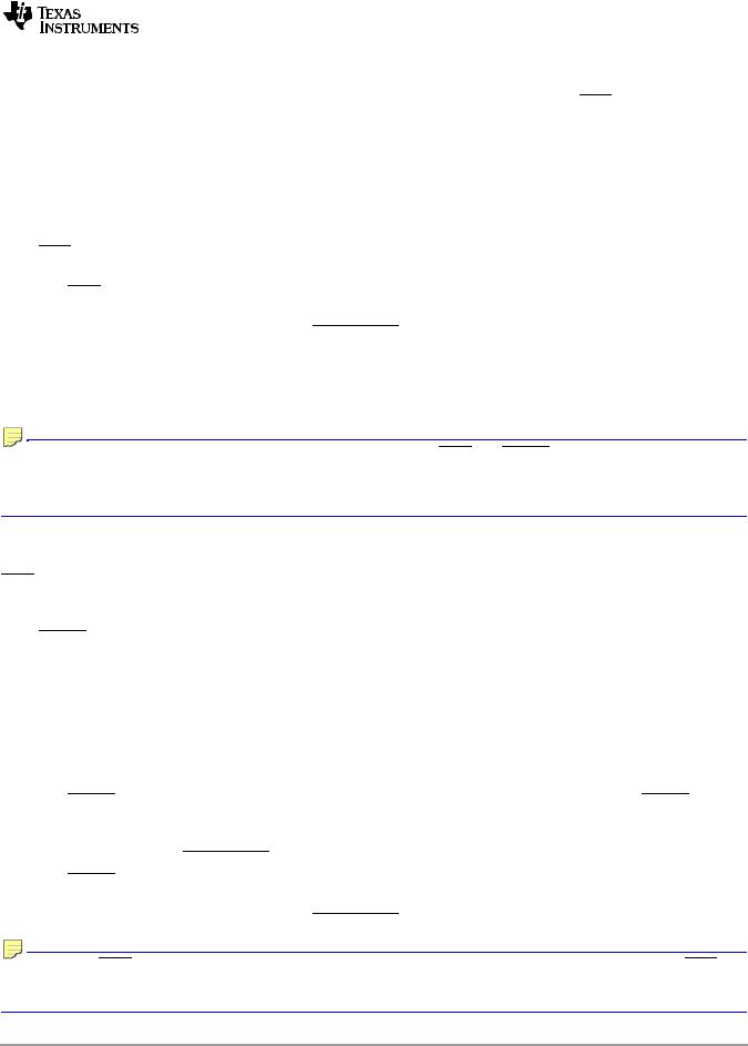
Figure 7-14 POR Reset Timing
1
2
VDDS15 Stable + Clocks Valid (internal signal)
POR
RESET
RESETFULL
3
RESETSTAT
152 |
Copyright 2011 Texas Instruments Incorporated |
TMS320TCI6616
Communications Infrastructure KeyStone SoC
www.ti.com |
|
SPRS624A—January 2011 |
|
|
|
|
|
|
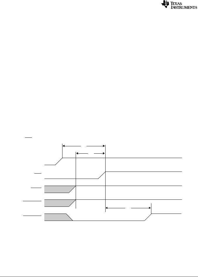
Figure 7-15 RESETFULL Reset Timing
4 
 5
5
6
RESETFULL
RESET
7
RESETSTAT
POR
Figure 7-16 Hard-Reset Timing
8 
 9
9
10
RESET
RESETFULL
11
RESETSTAT
POR
Figure 7-17 Soft-Reset Timing
 12
12 
 13
13 
14
RESET
RESETFULL
15
RESETSTAT
POR
ADVANCE INFORMATION
Copyright 2011 Texas Instruments Incorporated |
153 |
INFORMATION ADVANCE
TMS320TCI6616 |
|
|
|
|
|
|
|
|
|||||
Communications Infrastructure KeyStone SoC |
|
|
|
||||||||||
SPRS624A—January 2011 |
|
|
|
|
|
|
|
www.ti.com |
|||||
|
|
|
|
|
|
|
|
|
|
|
|
|
|
Table 7-45 Boot Configuration Timing Requirements (1) (2) |
|
|
|
||||||||||
See Figure 7-18) |
|
|
|
|
|
|
|
|
|||||
|
|
|
|
|
|
|
|
|
|
|
|
|
|
No. |
|
|
|
|
|
|
|
|
|
|
Min |
Max |
Unit |
1 |
tsu(GPIOn- |
|
|
Setup Time - GPIO valid before |
|
|
asserted |
12C |
|
ns |
|||
POR) |
POR |
|
|||||||||||
2 |
|
|
-GPIOn) |
|
|
|
|
|
12C |
|
ns |
||
th(POR |
Hold Time - GPIO valid after POR asserted |
|
|||||||||||
End of Table 7-45 |
|
|
|
|
|
|
|
|
|||||
|
|
|
|
|
|
|
|
|
|
|
|
|
|
1 If CORECLKSEL = 0, C = 1 ÷ CORECLK(N|P) frequency in ns. 2 If CORECLKSEL = 1, C = 1 ÷ ALTCORECLK frequency in ns.
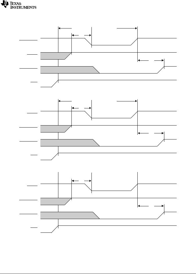
Figure 7-18 Boot Configuration Timing
1
POR
GPIO[15:0]
2
154 |
Copyright 2011 Texas Instruments Incorporated |