

a
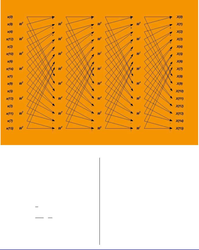
Figure 2. Reorganized Structure of the 16-Point FFT
It is simple enough to trace this diagram by hand to see that it is simply a re-ordering of the diagram in Figure 1. Amazingly enough, the final output is in correct order. This can be easily proven for general N = 2k = the number of points in the FFT. Note that the re-ordering is given by the following formula:
n , if n is even f (n) = 2
n −1 + N , if n is odd2 2
Thus, if n is even, it is shifted right and if n is odd, it is shifted right and its most significant bit is set. This is, of course, equivalent to the
operation of |
right 1-bit rotation, which after |
K = log2 (N ) |
steps returns the original n back. |
Thus, the output after K stages is in correct order again.
Great! We have our new structure. It has sequential reads and we are lucky enough that the output is in the correct order. This should be much more efficient. Right? Let’s write the code for it! Well, before we spend a lot of time writing the code, we should ensure that all of the DSP operations that we are about to do actually fit into our processor architecture efficiently. There may be no reason to optimize data movements if the underlying math suffers.
Writing Efficient Floating-Point FFTs for ADSP-TS201 TigerSHARC® Processors (EE-218) |
Page 4 of 16 |

The first obvious point to notice is that this structure cannot be done in-place due to its reordering. The stages will have to ping-pong their input/output buffers. This should not be a problem. The ADSP-TS201 processor has a lot of memory on board, but should memory optimization be required (and input does not have to be preserved), we can use the input as one of the two ping-pong buffers.
Next, we note that a traditional FFT combines butterflies that share twiddles into the same group to save twiddle fetch cycles. Amazingly, the twiddles of the structure in Figure 2 line up linearly – one group at a time. We are lucky again!
Now, what would a butterfly of this new structure consist of? Table 2 lists the operations necessary to perform a single complex butterfly. Since the ADSP-TS201 is a SIMD processor (i.e., it can double all the computes), we will write the steps outlined in Listing 1 in SIMD fashion, so that two adjacent butterflies are computed in parallel, one in the X-Compute block and the other one in the Y-Compute block. Let us analyze the DSP operations in more detail. F1, F2, K2 and F4 fetch a total of four 32-bit words, which on ADSP-TS201 can be done in a single quad fetch into X-Compute block registers. To be able to supply SIMD machine with data, we would also have to perform a second butterfly quad fetch into the Y-Compute block registers. Then, M1, M2, M3, M4, A1, and A2 will perform SIMD operations for both butterflies.
The ADSP-TS201 supports a single add/subtract instruction, so A3 and A4 can be combined into a single operation (which is, of course, performed SIMD on both butterflies at once) and similarly A5 and A6 can be combined, as well.
|
|
|
|
a |
|
|
|
|
|
|
Mnemonic |
|
|
Operation |
|
|
|
|
|
|
F1 |
|
|
Fetch Real(Input1) of the Butterfly |
|
|
|
|
|
|
F2 |
|
|
Fetch Imag(Input1) of the Butterfly |
|
|
|
|
|
|
K2 |
|
|
Fetch Real(Input2) of the Butterfly |
|
|
|
|
|
|
F4 |
|
|
Fetch Imag(Input2) of the Butterfly |
|
|
|
||
|
|
|
|
|
|
M1 |
|
|
K2 * Real(twiddle) |
|
|
|
|
|
|
M2 |
|
|
F4 * Imag(twiddle) |
|
|
|
|
|
|
M3 |
|
|
K2 * Imag(twiddle) |
|
|
|
|
|
|
M4 |
|
|
F4 * Real(twiddle) |
|
|
|
||
|
|
|
|
|
|
A1 |
|
|
M1–M2 = Real(Input2*twiddle) |
|
|
|
|
|
|
A2 |
|
|
M3+M4 = Imag(Input2*twiddle) |
|
|
|
|
|
|
A3 |
|
|
F1 + A1 = Real(Output1) |
|
|
|
|
|
|
A4 |
|
|
F1 - A1 = Real(Output2) |
|
|
|
|
|
|
A5 |
|
|
F2 + A2 = Imag(Output1) |
|
|
|
|
|
|
A6 |
|
|
F2 – A2 = Imag(Output2) |
|
|
|
||
|
|
|
|
|
|
S1 |
|
|
Store(Real(Output1)) |
|
|
|
|
|
|
S2 |
|
|
Store(Imag(Output1)) |
|
|
|
|
|
|
S3 |
|
|
Store(Real(Output2)) |
|
|
|
|
|
|
S4 |
|
|
Store(Imag(Output2)) |
|
|
|
|
|
Table 2. Single Butterfly Done Linearly – Logical
Implementation
Now we run into a problem: S1, S2, S3 and S4 cannot be performed in the same cycle, since S3 and S4 are destined to another place in memory due to our output re-ordering. Instead, we can store S1 and S2 for both butterflies in one cycle (lucky again – these are adjacent!) and S3 and S4 for both butterflies in the next cycle. So far, so good – the new set of operations is summarized in Table 3.
Writing Efficient Floating-Point FFTs for ADSP-TS201 TigerSHARC® Processors (EE-218) |
Page 5 of 16 |

Mnemonic |
Operation |
|
|
F1 |
Fetch Input1,2 of the Butterfly1 |
|
|
F2 |
Fetch Input1,2 of the Butterfly2 |
|
|
M1 |
Real(Input2) * Real(twiddle) |
|
|
M2 |
Imag(Input2) * Imag(twiddle) |
|
|
M3 |
Real(Input2) * Imag(twiddle) |
|
|
M4 |
Imag(Input2) * Real(twiddle) |
|
|
A1 |
M1–M2 = Real(Input2*twiddle) |
|
|
A2 |
M3+M4 = Imag(Input2*twiddle) |
|
|
A3 |
Real(Input1) +/- A1 = Real(Output1,2) |
|
|
A4 |
Imag(Input1) +/- A2 = Imag(Output1) |
|
|
S1 |
Store(Output1, both Butterflies) |
|
|
S2 |
Store(Output2, both Butterflies) |
|
|
Table 3. Single Butterfly Done Linearly – Actual
ADSP-TS20x Implementation
Each operation in Table 3 is a single-cycle operation on ADSP-TS201 processor. There is a total of 2 fetches, 4 multiplies, 4 ALU, and 2 store instructions. Since the ADSP-TS201 allows fetches/stores to be paralleled with multiplies and ALUs in a single cycle, loop unrolling, pipelining, and paralleling should yield a 4-cycle execution of these two SIMD butterflies (and we are still efficient in the memory usage!). At this point, we can now be reasonably certain that the above will yield efficient code and we can start developing it. However, careful observation at this point can help us optimize this structure even further. Note that we are only using a total of 4 fetches and stores from a single memory block, say, by using JALU pointer registers. In parallel we can do 3 more fetches/stores/KALU operations without losing any cycles (actually, we can do 4 of them, but we do need one
a
reserved place in one of the instructions for a loop jump back).
Thus, the old rule of fetching twiddles only once per group of butterflies that shares them is no longer necessary – the twiddle fetches come free! And, since the structure of the arrows of Figure 2 is identical at every stage, we may be able to reduce the FFT from the usual three nested loops to only two, provided that we can find a way to correctly fetch the twiddles at each stage (twiddles are the only thing that distinguishes the stages of Figure 2). Figure 2 shows how the twiddles must be fetched at each stage: 1st Stage
– all are W0. 2nd Stage – half are W0, next half are WN/4. 3rd Stage – one quarter are W0, the next quarter are WN/8, the next quarter are W2N/8, and the last quarter are W3N/8. And so on… If we
keep a virtual twiddle pointer offset, increment it to the next sequential twiddle every butterfly, but AND it with a mask before actually using it in the twiddle fetch, we achieve precisely this order of twiddle fetch. Moreover, this rule is the same for every stage, except that the mask at every stage must be shifted down by one bit (i.e., each stage requires twice as fine a resolution of the twiddles as the previous stage). Here, our unused KALU operations come in very handy. To implement this twiddle fetch, we need to increment the virtual offset, mask it and do a twiddle fetch every butterfly… Oh, no! We are in SIMD (i.e. we are doing two butterflies together) and we do not have the 6 available instruction slots for this! But luck saves us again. We can easily notice that all stages except the last share the twiddles between the SIMD pair of butterflies – so, for these stages, we need only to do the twiddle fetch once per SIMD pair of the butterflies! And the three cycles are precisely what we have to do this. Unfortunately, in the last stage, every butterfly has its own unique twiddle; but in the last stage, we do not have to mask – just step the pointer to the next twiddle every time! It will have to be written separately, but it will optimize completely as well. Table 4 summarizes the latest structure’s steps. Three
Writing Efficient Floating-Point FFTs for ADSP-TS201 TigerSHARC® Processors (EE-218) |
Page 6 of 16 |