

TMS320C15, TMS320E15, TMS320P15
DIGITAL SIGNAL PROCESSORS
SPRS009C ± JANUARY 1987 ± REVISED JULY 1991
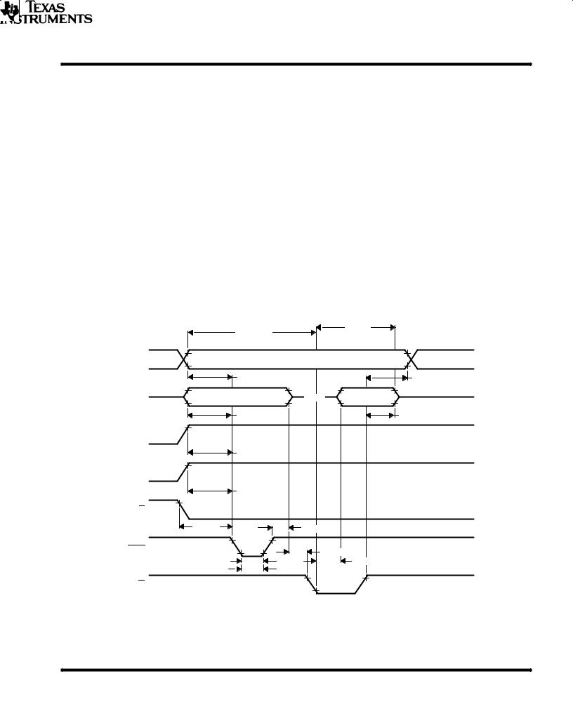
TBLR instruction timing
|
CLKOUT |
|
|
|
|
|
|
|
|
|
td3 |
td2 |
td3 |
|
MEN |
1 |
|
2 |
3 |
4 |
|
|
|
||||
|
|
|
|
|
td1 |
|
|
A11-A0 |
5 |
|
6 |
7 |
8 |
|
|
|
|
|
tsu(D) |
th(D) |
|
|
|
|
|
|
|
|
D15-D0 |
9 |
|
10 |
11 |
12 |
Legend: |
|
|
|
|
|
|
1. |
TBLR Instruction Prefetch |
|
7. |
Address Bus Valid |
|
|
2. |
Dummy Prefetch |
|
8. |
Address Bus Valid |
|
|
3. |
Data Fetch |
|
9. |
Instruction Valid |
|
|
4. |
Next Instruction Prefetch |
|
10. |
Instruction Valid |
|
|
5. |
Address Bus Valid |
|
11. |
Data Input Valid |
|
|
6. |
Address Bus Valid |
|
12. |
Instruction Valid |
|
|
TBLW instruction timing
CLKOUT
|
MEN |
1 |
|
2 |
|
3 |
|
|
|
|
|||
|
A11-A0 |
4 |
|
5 |
6 |
7 |
|
|
|
|
|
td6 |
td7 |
|
WE |
|
|
|
|
|
|
|
|
|
|
td8 |
tv |
|
|
|
|
|
td9 |
td10 |
|
D15-D0 |
|
8 |
9 |
10 |
11 |
Legend: |
|
|
|
|
|
|
1. |
TBLW Instruction Prefetch |
|
7. |
Address Bus Valid |
|
|
2. |
Dummy Prefetch |
|
8. |
Instruction Valid |
|
|
3. |
Next Instruction Prefetch |
|
9. |
Instruction Valid |
|
|
4. |
Address Bus Valid |
|
10. |
Data Output Valid |
|
|
5. |
Address Bus Valid |
|
11. |
Instruction Valid |
|
|
6. |
Address Bus Valid |
|
|
|
|
|
POST OFFICE BOX 1443 • HOUSTON, TEXAS 77001 |
61 |

TMS320C15, TMS320E15, TMS320P15
DIGITAL SIGNAL PROCESSORS
SPRS009C± JANUARY 1987 ± REVISED JULY 1991
IN instruction timing
CLKOUT
|
MEN |
1 |
|
|
2 |
|
|
|
tsu(A-MD) |
||
|
|
|
|
tsu(D) |
|
|
|
|
|
|
|
|
A11-A0 |
3 |
|
4 |
5 |
|
|
|
|
td4 |
td5 |
|
DEN |
|
|
|
|
|
|
|
|
|
th(D) |
|
D15-D0 |
|
6 |
7 |
8 |
Legend: |
|
|
|
|
|
1. |
IN Instruction Prefetch |
|
5. |
Address Bus Valid |
|
2. |
Next Instruction Prefetch |
|
6. |
Instruction Valid |
|
3. |
Address Bus Valid |
|
7. |
Data Input Valid |
|
4. |
Peripheral Address Valid |
|
8. |
Instruction Valid |
|
OUT instruction timing
CLKOUT
|
MEN |
1 |
|
|
2 |
|
A11-A0 |
3 |
|
4 |
5 |
|
|
|
td6 |
|
td7 |
|
WE |
td9 |
|
td10 |
|
|
|
|
td8 |
tv |
|
|
|
|
|
||
|
D15-D0 |
6 |
|
7 |
8 |
Legend: |
|
|
|
|
|
1. |
IN Instruction Prefetch |
5. |
Address Bus Valid |
|
|
2. |
Next Instruction Prefetch |
6. |
Instruction Valid |
|
|
3. |
Address Bus Valid |
7. |
Data Output Valid |
|
|
4. |
Peripheral Address Valid |
8. |
Instruction Input Valid |
|
|
62 |
POST OFFICE BOX 1443 • HOUSTON, TEXAS 77001 |

TMS320C15, TMS320E15, TMS320P15
DIGITAL SIGNAL PROCESSORS
SPRS009C ± JANUARY 1987 ± REVISED JULY 1991
reset timing
CLKOUT |
|
|
|
|
|
|
tsu(R) |
tsu(R) |
|
RS |
|
|
|
|
|
|
tw(R) |
|
|
DEN |
|
|
|
|
WE see |
|
Data In From |
Data In From |
|
MEN Note E |
td11 |
PC ADDR 0 |
PC ADDR PC+1 |
|
|
tdis(R) |
Data Shown Relative to WE |
|
|
D15-D0 |
|
|
|
|
|
|
|
|
|
MEN |
|
|
|
|
|
AB = Address Bus |
|
AB = PC+1 |
|
Address |
AB = PC |
AB = PC+1 |
AB = PC = 0 |
|
Bus |
|
|||
|
|
|
|
|
NOTES: A. RS forces DEN, WE, and MEN high and places data bus D0 through D15 in a high-impedance state. AB outputs (and program count- er) are synchronously cleared to zero after the next complete CLK cycle from RS↓.
B.RS must be maintained for a minimum of five clock cycles.
C.Resumption of normal program will commence after one complete CLK cycle from RS↑.
D.Due to the synchronization action on RS, time to execute the function can vary dependent upon when RS↑ or RS↓occur in the CLK cycle.
E.Diagram shown is for definition purpose only. DEN, WE, and MEN are mutually exclusive.
F.During a write cycle, RS may produce an invalid write address.
interrupt timing
CLKOUT
tsu(INT)
INT
tf(INT)
tw(INT)
BIO timing
CLKOUT
tsu(IO)
BIO
tf(IO)
tw(IO)
POST OFFICE BOX 1443 • HOUSTON, TEXAS 77001 |
63 |

TMS320E15, TMS320P15
DIGITAL SIGNAL PROCESSORS
SPRS009C± JANUARY 1987 ± REVISED JULY 1991
absolute maximum ratings over specified temperature range (unless otherwise noted)²
Supply voltage range, VPP (see Note 6) . . . . . . . . . . . . . . . . . . . . . . . . . . . . . . . . . . . . . . . . . . . . . . . . . . . |
±0.6 V to 14 V |
²Stresses beyond those listed under ªAbsolute Maximum Ratingsº may cause permanent damage to the device. This is a stress ratingonly, and functional operation of the device at these or any other conditions beyond those indicated in the ªRecommended Operating Conditionsº section of
this specification is not implied. Exposure to absolute-maximum-rated conditions for extended periods may affect device reliability. NOTE 6: All voltage values are with respect to VSS.
recommended operating conditions
|
MIN |
NOM |
MAX |
UNIT |
|
|
|
|
|
VPP Supply voltage (see Note 11) |
12.25 |
12.5 |
12.75 |
V |
NOTE 11: VPP can be applied only to programming pins designed to accept VPP as an input. During programming the total supply current is IPP + ICC.
electrical characteristics over specified temperature range (unless otherwise noted)
|
PARAMETER |
TEST CONDITIONS |
MIN |
TYP³ |
MAX |
UNIT |
IPP1 |
VPP supply current |
VPP = VCC 5.5 V |
|
|
100 |
V |
IPP2 |
VPP supply current (during program pulse) |
VPP = 12.75 V |
|
30 |
50 |
V |
³ All typical values except for ICC are at VCC = 5 V, TA = 25°C.
recommended timing requirements for programming, TA = 25°C, VCC = 6, VPP = 12.5 V,
(see Note 13)
|
|
|
|
|
|
|
|
MIN |
NOM |
MAX |
UNIT |
|
|
|
|
|
|
|
|
|
|
|
|
tw(IPGM) |
Initial program pulse duration |
0.95 |
1 |
1.05 |
ms |
||||||
tw(FPGM) |
Final pulse duration |
3.8 |
|
63 |
ms |
||||||
tsu(A) |
Address setup time |
2 |
|
|
s |
||||||
tsu(E) |
|
setup time |
2 |
|
|
s |
|||||
E |
|
|
|
||||||||
tsu(G) |
|
|
setup time |
2 |
|
|
s |
||||
G |
|
|
|||||||||
|
Output disable time from |
|
|
(see Note |
|
|
|
|
|||
tdis(G) |
G |
0 |
|
130§ |
ns |
||||||
15) |
|
|
|
|
|
||||||
|
|
|
|
|
|
|
|
|
|||
|
|
|
|
|
|
||||||
t |
Output enable time from |
|
|
|
|
0 |
|
150§ |
ns |
||
G |
|
|
|||||||||
en(G) |
|
|
|
|
|
|
|
|
|
|
|
tsu(D) |
Data setup time |
2 |
|
|
s |
||||||
tsu(VPP) |
VPP setup time |
2 |
|
|
s |
||||||
tsu(VCC) |
VCC setup time |
2 |
|
|
s |
||||||
th(A) |
Address hold time |
0 |
|
|
s |
||||||
th(D) |
Data hold time |
2 |
|
|
s |
||||||
§ Values derived from characterization data and not tested.
NOTES: 13. For all switching characteristics and timing measurements, input pulse levels are 0.4 V to 2.4 V and VPP = 12.5 V ± 0.5 V during programming.
15. Common test conditions apply for tdis(G) except during programming.
64 |
POST OFFICE BOX 1443 • HOUSTON, TEXAS 77001 |

TMS320E15, TMS320P15
DIGITAL SIGNAL PROCESSORS
SPRS009C ± JANUARY 1987 ± REVISED JULY 1991
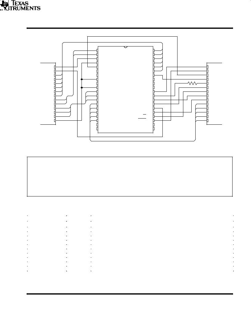
PROGRAMMING THE TMS320E15/P15 EPROM CELL
′E15/P15 devices include a 4K × 16-bit industry-standard EPROM cell for prototyping, early field testing, and low-volume production. In conjunction with this EPROM, the ′E15/P15 with a 4K-word masked ROM, then, provide more migration paths for cost-effective production.
EPROM adapter sockets are available that provide pin-to-pin conversions for programming any ′E15/P15 devices. One adapter socket (part number RTC/PGM320C-06), shown in Figure 8, converts a 40-pin DIP device into an equivalent 28-pin device. Another socket (part number RTC/PGM320A-06), not shown, permits 44to 28-pin conversion.
Figure 8. EPROM Adapter Socket (40-pin to 28-pin DIP Conversion)
Key features of the EPROM cell include the normal programming operation as well as verification. The EPROM cell also includes a code protection feature that allows code to be protected against copyright violations.
The ′E15/P15 EPROM cell is programmed using the same family and device pinout codes as the TMS27C64 8K × 8-bit EPROM. The TMS27C64 EPROM series are unltraviolet-light erasable, electrically programmable, read-only memories, fabricated using HVCMOS technology. They are pin-compatible with existing 28-pin ROMs and EPROMs. These EPROMs operate from a single 5-V supply in the read mode; however, a 12.5-V supply is needed for programming. All programming signals are TTL level. For programming outside the system, existing EPROM programmers can be used. Locations may be programmed singly, in blocks, or at random.
Figure 9 shows the wiring conversion to program the ′E15/P15 using the 28-pin pinout of the TMS27C64. Table 5 on pin nomenclature provides a description of the TMS27C64 pins. The code to be programmed into the device should be in serial mode. The ′E15/P15 devices use 13 address lines to address 4K-word memory in byte format.
POST OFFICE BOX 1443 • HOUSTON, TEXAS 77001 |
65 |
TMS320E15, TMS320P15
DIGITAL SIGNAL PROCESSORS
SPRS009C± JANUARY 1987 ± REVISED JULY 1991
|
|
1 |
A1 |
A2 |
40 |
|
|
|
|
|
2 |
A0(LSB) |
A3 |
39 |
|
|
|
|
|
3 |
VPP |
A4 |
38 |
|
|
|
|
|
4 |
RS |
A5 |
37 |
|
28 |
VCC |
VPP |
1 |
5 |
EPT |
A6 |
36 |
|
||
A12 |
2 |
6 |
|
A7 |
35 |
|
27 |
PGM |
A7 |
3 |
7 |
|
A8 |
34 |
|
26 |
EPT |
A6 |
4 |
8 |
CLKIN |
|
33 |
3.9 kΩ |
25 |
A8 |
A5 |
5 |
9 |
|
|
32 |
24 |
A9 |
|
|
|
|
||||||
A4 |
6 |
10 |
GND |
|
31 |
|
23 |
A11 |
A3 |
7 |
11 |
Q1(LSB) |
VCC 30 |
|
22 |
G |
|
A2 |
8 |
12 |
Q2 |
A9 |
29 |
|
21 |
A10 |
A1 |
9 |
13 |
Q3 |
A10 |
28 |
|
20 |
E |
A0 |
10 |
14 |
Q4 |
A11 |
27 |
|
19 |
Q8 |
Q1 |
11 |
15 |
Q5 |
(MSB)A12 |
26 |
|
18 |
Q7 |
Q2 |
12 |
16 |
Q6 |
E 25 |
|
17 |
Q6 |
|
Q3 |
13 |
17 |
Q7 |
G 24 |
|
16 |
Q5 |
|
GND 14 |
18 |
Q8(MSB) |
PGM 23 |
|
15 |
Q4 |
||
TMS27C64 |
19 |
|
|
22 |
|
TMS27C64 |
||
20 |
TMS320E15/P15 |
21 |
|
|||||
PINOUT |
|
|
|
|
|
PINOUT |
||
CAUTION
Although acceptable by some EPROM programmers, the signature mode cannot be used on any ′E1x device. The signature mode will input a high-level voltage (12.5 Vdc) onto pin A9. Since this pin is not designed for high voltage, the cell will be damaged. To prevent an accidental application of voltage, Texas Instruments has inserted a 3.9 kΩ resistor between pin A9 of the TI programmer socket and the programmer itself.
|
|
|
|
|
|
|
Pin Nomenclature (TMS320E15/P15) |
|
|
|
|
|
|
|
|
|
|
|
|
|
NAME |
I/O |
DEFINITION |
|
|
|
|
|
|
|
|
|
A0-A12 |
I |
On-chip EPROM programming address lines |
||||
|
CLKIN |
I |
Clock oscillator input |
||||
|
E |
|
|
|
|
I |
EPROM chip select |
|
EPT |
I |
EPROM test mode select |
||||
|
G |
|
|
|
I |
EPROM read/verify select |
|
|
GND |
I |
Ground |
||||
|
PGM |
|
I |
EPROM write/program select |
|||
|
Q1-Q8 |
I/O |
Data lines for byte-wide programming of on-chip 8K bytes of EPROM |
||||
|
RS |
|
I |
Reset for initializing the device |
|||
|
VCC |
I |
5-V power supply |
||||
|
VPP |
I |
12.5-V power supply |
||||
Figure 9. TMS320E15/P15 EPROM Programming Conversion to TMS27C64 EPROM Pinout
66 |
POST OFFICE BOX 1443 • HOUSTON, TEXAS 77001 |
TMS320E15, TMS320P15
DIGITAL SIGNAL PROCESSORS
SPRS009C ± JANUARY 1987 ± REVISED JULY 1991
Table 5 shows the programming levels required for programming, verifying, reading, and protecting the EPROM cell.
Table 5. TMS320E15/P15 Programming Mode Levels
SIGNAL NAME |
TMS320E15 PIN |
TMS27C64 PIN |
PROGRAM |
VERIFY |
|
READ |
PROTECT VERIFY |
EPROM PROTECT |
||||||||||||||
|
|
|
|
|
|
|
|
|
|
|
|
|
|
|
|
|
|
|
|
|
|
|
|
|
|
|
|
|
|
|
25 |
20 |
|
VIL |
|
VIL |
|
VIL |
VIL |
VIH |
|||||
|
|
|
E |
|
|
|
|
|
|
|
||||||||||||
|
|
|
|
|
|
|
|
24 |
22 |
|
VIH |
|
|
|
|
|
|
VIL |
VIH |
|||
|
|
|
G |
|
|
|
|
|
PULSE |
|
|
PULSE |
|
|||||||||
|
|
|
|
|
|
|
|
23 |
27 |
|
|
|
|
VIH |
|
VIH |
VIH |
VIH |
||||
|
PGM |
|
|
PULSE |
|
|
|
|||||||||||||||
|
VPP |
3 |
1 |
|
VPP |
|
VPP |
|
VCC |
VCC + 1 |
VPP |
|||||||||||
|
VCC |
30 |
28 |
|
VCC |
|
VCC |
|
VCC |
VCC + 1 |
VCC + 1 |
|||||||||||
|
VSS |
10 |
14 |
|
VSS |
|
VSS |
|
VSS |
VSS |
VSS |
|||||||||||
CLKIN |
8 |
14 |
|
VSS |
|
VSS |
|
VSS |
VSS |
VSS |
||||||||||||
|
|
|
|
|
|
|
|
4 |
14 |
|
VSS |
|
VSS |
|
VSS |
VSS |
VSS |
|||||
|
|
RS |
|
|
|
|
||||||||||||||||
|
EPT |
5 |
26 |
|
VSS |
|
VSS |
|
VSS |
VPP |
VPP |
|||||||||||
Q1-Q8 |
11-18 |
11-13, 15-19 |
|
DIN |
|
QOUT |
|
QOUT |
Q8=RBIT |
|
|
|
||||||||||
|
|
|
Q8=PULSE |
|
||||||||||||||||||
A0-A3 |
2, 1, 40, 39 |
10-7 |
|
ADDR |
|
ADDR |
|
ADDR |
X |
|
X |
|||||||||||
|
|
|
|
|
|
|
|
|
|
|
|
|
||||||||||
|
|
A4 |
38 |
6 |
|
ADDR |
|
ADDR |
|
ADDR |
X |
VIH |
||||||||||
|
|
A5 |
37 |
5 |
|
ADDR |
|
ADDR |
|
ADDR |
X |
|
X |
|||||||||
|
|
|
|
|
|
|
|
|
|
|
|
|
|
|||||||||
|
|
A6 |
36 |
4 |
|
ADDR |
|
ADDR |
|
ADDR |
VIL |
|
X |
|||||||||
A7-A9 |
35, 34, 29 |
3, 25, 24 |
|
ADDR |
|
ADDR |
|
ADDR |
X |
|
X |
|||||||||||
|
|
|
|
|
|
|
|
|
|
|
|
|||||||||||
A10-A12 |
28-26 |
21, 23, 2 |
|
ADDR |
|
ADDR |
|
ADDR |
X |
|
X |
|||||||||||
|
|
|
|
|
|
|
|
|
|
|
|
|
|
|
|
|
|
|
|
|
|
|
Legend:
VIH = TTL high level; VIL = TTL low level; ADDR = byte address bit
VPP = 12.5 V ± 0.25 V; VCC = 5 V ± 0.25 V; X = don't care
PULSE = low-going TTL level pulse; DIN = byte to be programmed at ADDR
QOUT = byte stored at ADDR; RBIT = ROM protect bit.
programming
Since every memory bit in the cell is a logic 1, the programming operation reprograms certain bits to 0. Once programmed, these bits can only be erased using ultraviolet light. The correct byte is placed on the data bus with VPP set to the 12.5 V level. The PGM pin is then pulsed low to program in the zeros.
erasure
Before programming, the device must be erased by exposing it to ultraviolet light. The recommended minimum exposure dose (UV-intensity ×exposure-time) is 15 W•s/cm2. A typical 12-mW/cm2, filterless UV lamp will erase the device in 21 minutes. The lamp should be located about 2.5 cm above the chip during erasure. After exposure, all bits are in the high state.
verify/read
To verify correct programming, the EPROM cell can be read using either the verify or read line definitions shown in Table 5, assuming the inhibit bit has not been programmed.
program inhibit
Programming may be inhibited by maintaining a high level input on the E pin or PGM pin.
read
The EPROM contents may be read independent of the programming cycle, provided the RBIT (ROM protect bit) has not been programmed. The read is accomplished by setting E to zero and pulsing G low. The contents of the EPROM location selected by the value on the address inputs appear on Q8-Q1.
POST OFFICE BOX 1443 • HOUSTON, TEXAS 77001 |
67 |
TMS320E15, TMS320P15
DIGITAL SIGNAL PROCESSORS
SPRS009C± JANUARY 1987 ± REVISED JULY 1991
output disable
During the EPROM programming process, the EPROM data outputs may be disabled, if desired, by establishing the output disable state. This state is selected by setting G and E pins high. While output disable is selected, Q8-Q1are placed in the high-impedance state.
EPROM protection
To protect the proprietary algorithms existing in the code programmed on-chip, the ability to read or verify code from external accesses can be completely disabled. Programming the RBIT disables external access of the EPROM cell and disables the microprocessor mode, making it impossible to access the code resident in the EPROM cell. The only way to remove this protection is to erase the entire EPROM cell, thus removing the proprietary information. The signal requirements for programming this bit are shown in Table 5. The cell can be determined as protected by verifying the programming of the RBIT shown in the table.
standard programming procedure
Before programming, the device must first be completely erased. Then the device can be programmed with the correct code. It is advisable to program unused sections with zeroes as a further security measure. After the programming is complete, the code programmed into the cell should be verified. If the cell passes verification, the next step is to program the ROM protect bit (RBIT). Once the RBIT programming is verified, an opaque label should be placed over the window to protect the EPROM cell from inadvertent erasure by ambient light. At this point, the programming is complete, and the device is ready to be placed into its destination circuit.
program cycle timing
|
Program |
|
Verify |
|
|
|
|
|
|
||
A12-A0 |
|
Address Stable |
|
|
VIH |
|
|
|
Address N+1 |
||
|
tsu(A) |
|
|
|
VIL |
|
|
|
|
th(A) |
|
|
|
|
|
Data Out |
VIH/VOH |
Q8-Q1 |
Data In Stable |
HI-Z |
|
|
|
|
Valid |
VIL/VOL |
|||
|
|
|
|
||
|
|
|
|
|
|
|
tsu(D) |
|
|
|
tdis(G) |
VPP |
|
|
|
|
VPP |
|
|
|
|
|
|
|
tsu(VPP) |
|
|
VCC |
|
|
|
|
VCC+1 |
||
VCC |
|
|
|
|
|
|
|
|
|
|
|
|
tsu(VCC) |
|
|
VCC |
|
|
|
|
VIH |
||
E |
|
|
|
|
|
|
|
|
|
|
|
|
tsu(E) |
th(D) |
|
|
VIL |
|
|
|
VIH |
||
|
|
|
|
|
|
PGM |
tw(IPGM) |
|
tsu(G) |
ten(G) |
VIL |
|
|
|
|||
|
tw(FPGM) |
|
|
|
VIH |
G |
|
|
|
|
|
|
|
|
|
|
|
|
|
|
|
|
VIL |
68 |
POST OFFICE BOX 1443 • HOUSTON, TEXAS 77001 |

TMS320LC15
DIGITAL SIGNAL PROCESSOR
SPRS009C ± JANUARY 1987 ± REVISED JULY 1991
absolute maximum ratings over specified temperature range (unless otherwise noted)²
Supply voltage range, VCC (see Note 6) . . . . . . . . . . . . . . . . . . . . . . . . . . . . . . . . . . . . . . . . . . . . . . . . . . ±0.3 V to 4.6 V Input voltage range . . . . . . . . . . . . . . . . . . . . . . . . . . . . . . . . . . . . . . . . . . . . . . . . . . . . . . . . . . . . . . . . . . ±0.3 V to VCC + 0.5 Output voltage range . . . . . . . . . . . . . . . . . . . . . . . . . . . . . . . . . . . . . . . . . . . . . . . . . . . . . . . . . . . . . . . . ±0.3 V to VCC + 0.5 Continuous power dissipation . . . . . . . . . . . . . . . . . . . . . . . . . . . . . . . . . . . . . . . . . . . . . . . . . . . . . . . . . . . . . . . . . . . . 75 mW
Air temperature range above operating devices: L version . . . . . . . . . . . . . . . . . . . . . . . . . . . . . . . . . . . . . 0°C to 70°C A version . . . . . . . . . . . . . . . . . . . . . . . . . . . . . . . . . . ±40°C to 85°C Storage temperature range . . . . . . . . . . . . . . . . . . . . . . . . . . . . . . . . . . . . . . . . . . . . . . . . . . . . . . . . . . . . ±55°C to +150°C
²Stresses beyond those listed under ªAbsolute Maximum Ratingsº may cause permanent damage to the device. This is a stress ratingonly, and functional operation of the device at these or any other conditions beyond those indicated in the ªRecommended Operating Conditionsº section of
this specification is not implied. Exposure to absolute-maximum-rated conditions for extended periods may affect device reliability.
NOTE 6: All voltage values are with respect to VSS.
recommended operating conditions
|
|
|
MIN |
NOM |
MAX |
UNIT |
|
|
|
|
|
|
|
VCC |
Supply voltage |
|
3.0 |
3.3 |
3.6 |
V |
VSS |
Supply voltage |
|
|
0 |
|
V |
VIH |
High-level input voltage |
All inputs except CLKIN |
2.0 |
|
|
V |
|
|
|
|
|
||
CLKIN |
2.5 |
|
|
V |
||
|
|
|
|
|||
|
|
|
|
|
|
|
VIL |
Low-level input voltage |
All inputs |
|
|
0.55 |
V |
IOH |
High-level output current (all outputs) |
|
|
|
± 300 |
A |
IOL |
Low-level output current (all outputs) |
|
|
|
1.5 |
mA |
TA |
Operating free-air temperature |
L version |
0 |
|
70 |
°C |
|
|
|
|
|
||
A version |
± 40 |
|
85 |
°C |
||
|
|
|
electrical characteristics over specified temperature range (unless otherwise noted)
|
PARAMETER |
|
TEST CONDITIONS |
|
MIN |
TYP² |
MAX |
UNIT |
||||
VOH |
High-level output voltage |
|
IOH = MAX |
|
|
2.0 |
|
|
V |
|||
|
I = 20 A (see Note 7) |
V |
CC |
± 0.4³ |
|
|
V |
|||||
|
|
|
|
|
OH |
|
|
|
|
|
|
|
VOL |
Low-level output voltage |
|
IOL = MAX |
|
|
|
|
|
0.5 |
V |
||
IOZ |
Off-state ouput current |
|
VCC = MAX, VO = VCC |
|
|
|
|
20 |
A |
|||
|
VO = VSS |
|
|
|
|
±20 |
||||||
|
|
|
|
|
|
|
|
|
|
|||
II |
Input current |
|
|
|
VI = VSS to VCC |
All inputs except CLKIN |
|
|
|
|
± 20 |
A |
|
|
|
VI = VSS to VCC |
CLKIN |
|
|
|
|
± 50 |
|||
|
|
|
|
|
|
|
|
|
|
|||
Ci |
Input capacitance |
|
|
Data bus |
|
|
|
|
|
25³ |
|
pF |
|
|
All others |
f = 1 MHz, All other pins 0 V |
|
|
|
15³ |
|
||||
Co |
Output capacitance |
|
Data bus |
|
|
|
25³ |
|
pF |
|||
|
|
|
|
|
|
|
||||||
|
All others |
|
|
|
|
|
10³ |
|
||||
|
|
|
|
|
|
|
|
|
|
|
||
² All typical values are at V |
CC |
= 3.3 V, T = 25°C. |
|
|
|
|
|
|
|
|||
|
|
|
A |
|
|
|
|
|
|
|
||
³ Values derived from characterization data and not tested.
NOTE 7: This voltage specification is included for interface to HC logic. However, note that all of the other timing parameters defined in this data sheet are specified for TTL logic levels and will differ for HC logic levels.
POST OFFICE BOX 1443 • HOUSTON, TEXAS 77001 |
69 |

TMS320LC15
DIGITAL SIGNAL PROCESSOR
SPRS009C± JANUARY 1987 ± REVISED JULY 1991
N Package
(Top View)
A1/PA1 |
1 |
40 |
|
A2/PA2 |
|||
A0/PA0 |
2 |
39 |
|
A3 |
|||
MC/MP |
3 |
38 |
|
A4 |
|||
|
RS |
4 |
37 |
|
A5 |
||
|
INT |
|
5 |
36 |
|
A6 |
|
CLKOUT |
6 |
35 |
|
A7 |
|||
|
X1 |
7 |
34 |
|
A8 |
||
X2/CLKIN |
8 |
33 |
|
MEN |
|
||
BIO |
9 |
32 |
|
DEN |
|||
VSS |
10 |
31 |
|
WE |
|||
|
D8 |
11 |
30 |
|
VCC |
||
|
D9 |
12 |
29 |
|
A9 |
||
D10 |
13 |
28 |
|
A10 |
|||
D11 |
14 |
27 |
|
A11 |
|||
D12 |
15 |
26 |
|
D0 |
|||
D13 |
16 |
25 |
|
D1 |
|||
D14 |
17 |
24 |
|
D2 |
|||
D15 |
18 |
23 |
|
D3 |
|||
|
D7 |
19 |
22 |
|
D4 |
||
|
D6 |
20 |
21 |
|
D5 |
||
FN Package
(Top View)
|
|
|
INT |
|
MC/MP |
A0/PA0 |
A1/PA1 |
|
A2/PA2 |
A3 |
A4 |
A5 |
A6 |
|
|
|
||||||||||
|
|
|
RS |
V |
|
|
|
|||||||||||||||||||
|
|
|
|
|
|
|
|
|
|
|
|
SS |
|
|
|
|
|
|
|
|
|
|
|
|
|
|
|
|
|
|
|
|
|
|
|
|
|
|
|
|
|
|
|
|
|
|
|
|
|
|
|
|
|
|
6 |
|
5 |
4 |
|
3 |
|
2 |
|
1 44 43 42 41 40 |
|
|
|
|||||||||||||
CLKOUT |
|
7 |
|
|
|
|
|
|
|
|
|
|
|
|
|
|
|
|
|
|
|
39 |
|
|
A7 |
|
|
|
|
|
|
|
|
|
|
|
|
|
|
|
|
|
|
|
|
|
|
||||||
X1 |
|
8 |
|
|
|
|
|
|
|
|
|
|
|
|
|
|
|
|
|
|
|
38 |
|
|
A8 |
|
|
|
|
|
|
|
|
|
|
|
|
|
|
|
|
|
|
|
|
|
|
||||||
X2/CLKIN |
|
9 |
|
|
|
|
|
|
|
|
|
|
|
|
|
|
|
|
|
|
|
37 |
|
|
MEN |
|
BIO |
|
10 |
|
|
|
|
|
|
|
|
|
|
|
|
|
|
|
|
|
|
|
36 |
|
|
DEN |
|
|
|
|
|
|
|
|
|
|
|
|
|
|
|
|
|
|
|
|
|
|
||||||
NC |
|
11 |
|
|
|
|
|
|
|
|
|
|
|
|
|
|
|
|
|
|
|
35 |
|
|
WE |
|
|
|
|
|
|
|
|
|
|
|
|
|
|
|
|
|
|
|
|
|
|
||||||
VSS |
|
12 |
|
|
|
|
|
|
|
|
|
|
|
|
|
|
|
|
|
|
|
34 |
|
|
VCC |
|
|
|
|
|
|
|
|
|
|
|
|
|
|
|
|
|
|
|
|
|
|
||||||
|
|
|
|
|
|
|
|
|
|
|
|
|
|
|
|
|
|
|
|
|
|
|
||||
D8 |
|
13 |
|
|
|
|
|
|
|
|
|
|
|
|
|
|
|
|
|
|
|
33 |
|
|
A9 |
|
D9 |
|
14 |
|
|
|
|
|
|
|
|
|
|
|
|
|
|
|
|
|
|
|
32 |
|
|
A10 |
|
|
|
|
|
|
|
|
|
|
|
|
|
|
|
|
|
|
|
|
|
|
||||||
D10 |
|
15 |
|
|
|
|
|
|
|
|
|
|
|
|
|
|
|
|
|
|
|
31 |
|
|
A11 |
|
|
|
|
|
|
|
|
|
|
|
|
|
|
|
|
|
|
|
|
|
|
||||||
D11 |
|
16 |
|
|
|
|
|
|
|
|
|
|
|
|
|
|
|
|
|
|
|
30 |
|
|
D0 |
|
|
|
|
|
|
|
|
|
|
|
|
|
|
|
|
|
|
|
|
|
|
||||||
D12 |
|
17 |
|
|
|
|
|
|
|
|
|
|
|
|
|
|
|
|
|
|
|
29 |
|
|
D1 |
|
|
|
|
|
|
|
|
|
|
|
|
|
|
|
|
|
|
|
|
|
|
||||||
|
18 19 20 21 22 23 24 25 26 27 28 |
|
|
|
||||||||||||||||||||||
|
|
|
|
|
|
|
|
|
|
|
|
|
|
|
|
|
|
|
|
|
|
|
|
|
|
|
|
|
|
V |
D13 |
D14 |
D15 |
D7 |
D6 |
D5 |
D4 |
D3 |
D2 |
V |
|
|
|
||||||||||
|
|
|
SS |
|
|
|
|
|
|
|
|
|
|
|
|
|
|
|
|
|
SS |
|
|
|
||
INTERNAL CLOCK OPTION
′320LC15
X1 X2/CLKIN
Crystal
C1 |
C2 |
PARAMETER MEASUREMENT INFORMATION
1.75 V
RL = 825 Ω
From Output
Under Test
Test
Point
CL = 100 pF
Figure 10. Test Load Circuit
70 |
POST OFFICE BOX 1443 • HOUSTON, TEXAS 77001 |