

Linear Engine / L2V4bGlicmlzL2R0bC9kM18xL2FwYWNoZV9tZWRpYS83MTc1
.pdfCsaba Tóth-Nagy |
Linear Engine Development for Series Hybrid Electric Vehicles |
3.8.4 Hydraulic or pneumatic pump
Linear engines can be connected to positive displacement, linear, hydraulic or pneumatic devices such as piston or membrane pumps to generate pressure or flow supply for hydraulic or pneumatic actuators or motors. Several different designs and arrangements were developed and simulated for various purposes during the past 40 years [39, 40, 60-69]. Amongst them, the dual piston configuration at Tampere University of Technology [64, 65] was a typical application and is shown in Figure 32. Tampere University’s design is called Emma2.
Figure 32. The dual piston hydraulic pump developed at Tampere University of Technology [65].
The Emma2 was a dual-piston, two-stoke, loop scavenged diesel linear engine that drove a hydraulic pump located between the cylinders. As it was a dual piston twostroke design, the Emma2 did not require assistance from the hydraulic pump to sustain operation. The piston diameter was 90 mm and the stroke was 120 mm. The engine applied a Ganser-Hydromag common rail injection system. Tikkanen et al. [65] reported 11.3 kW power output at 28 Hz operating frequency and 16:1 compression ratio. The engine was started using the hydraulic pump as a hydro-motor. Tikkanen et al. reported approximately 20% total efficiency for the Emma2 hydraulic free piston engine [65].
63

Csaba Tóth-Nagy |
Linear Engine Development for Series Hybrid Electric Vehicles |
Figure 33. The single piston hydraulic pump developed at Innas B.V. [62].
The single cylinder design at Innas B.V. [40, 60-63] stands out with its originality. Figure 33 shows the “CHIRON” of Innas B. V., a single cylinder linear engine hydraulic pump. As it was a two-stroke single-cylinder design, a hydraulic accumulator was applied to store energy during the power stroke that was used to drive the piston during the compression stroke. The CHIRON used pulse-pause modulation to control the operational frequency. When the piston was on the power stroke, the hydraulic pump used its power to pump the fluid as a useful power output. At the same time, part of the power was used to build up pressure in the compression accumulator through a check valve. Because the CHIRON was a single cylinder engine there was nothing that would push the piston up to cause compression. The system stopped and stayed in a standby state until the frequency control valve opened and let the pressure of the accumulator act on the compression piston that moved the piston towards TDC compressing the air in the cylinder. After compressing the air, fuel was injected and combustion took place resulting in a power cycle, pumping fluid from the low-pressure
64
Csaba Tóth-Nagy |
Linear Engine Development for Series Hybrid Electric Vehicles |
side to the high-pressure side as well as to the hydraulic accumulator. The process was repeated at the opening of the frequency control valve. Achten et al. [61] reported as low operating frequencies as necessary to provide the required flow rate or pressure. Actually the piston moves with similar speeds for different operating frequencies but it spends varying amount of time at BDC waiting for the frequency control valve to open realizing pulse-pause modulation.
The CHIRON had a stroke of 120-125 mm and a piston diameter of 110 mm. Its net effective power was 17 kW with up to 51% indicated efficiency. As Achten et al. concluded efficiency and emissions could be controlled by injection timing and the pressure in the compression accumulator [65]. The authors reported insignificant increase in exhaust emissions due to the cold start of the engine. They did not report on efficiency loss due to heat loss to the cold cylinder walls.
3.8.5 Electric generator
A linear engine can be coupled with a linear generator to form an electric generator set. The generator set can be used as a stand-alone mobile power generator or as an auxiliary power unit of a hybrid vehicle. Several research groups have performed conceptual analysis, simulation, and prototype design of the linear engine-alternator [59, 70-84]. The efforts of two scientist groups are shown here: Sandia National Laboratories [71-74] and West Virginia University [77-83]. The prototype “RCEM” (rapid compression-expansion machine) of Sandia National Laboratories can be seen in Figure 34.
65

Csaba Tóth-Nagy |
Linear Engine Development for Series Hybrid Electric Vehicles |
Figure 34. The homogeneous-charge compression-ignition linear engine-alternator developed at Sandia National Laboratories [73].
The linear engine developed at SNL had a dual piston arrangement and operated on a two-stroke cycle therefore the generator never had to work as a motor except for starting the engine. The RCEM was a homogeneously charged compression ignition two-stroke experimental linear engine. It operated at low equivalence ratio (0.3) and at high compression ratios (30:1-70:1). The homogeneous charge and the compression ignition allowed nearly constant volume burning in the cylinder, as a result, it let the engine achieve close to ideal Otto cycle efficiency. Van Blarigan [71] claimed that 95% of the fuel was burned in 80 µsec. This resulted in 48% thermal efficiency as the lowest value for the tested fuels in their experimental engine. Van Blarigan et al. [74] tested the experimental engine on eight different fuels and found as high as 56% efficiencies for propane and natural gas. The RCEM had a 76.2 mm bore and 254 mm maximum stroke. Researchers at SNL have not reported continuous operation. The prototype machine was tested on a single stroke at a time with homogeneous charge compressed to auto ignition in one cylinder with the aid of compressed helium providing the compressing force in the
66

Csaba Tóth-Nagy |
Linear Engine Development for Series Hybrid Electric Vehicles |
other. The linear alternator was used to control compression ratio for the study. The unit was estimated to provide around a maximum of 30 kW output power at an oscillating frequency of 40 Hz [71].
Previous research at WVU included the simulation of a four-cylinder four-stroke linear engine [59], the simulation of a two-cylinder two-stroke linear engine [78, 81, 83, 84, 85], and the development of a spark ignited two-cylinder two-stoke prototype linear engine [82]. The linear engine prototype developed at West Virginia University can be seen in Figure 35.
Figure 35. The linear engine developed at West Virginia University, 1st generation [82].
WVU’s 1st generation linear engine was also a dual-piston two-stroke model, similar to that of SNL. The main difference lied in the fact that WVU’s linear engine was
67
Csaba Tóth-Nagy |
Linear Engine Development for Series Hybrid Electric Vehicles |
spark ignited. The engine had 36.5 mm bore and a maximum stroke of 50 mm. Clark et al. [82] reported sustained operation under idling conditions as well as under load. A brushless permanent magnet DC alternator was used to apply load and gain power from the system. Load was reportedly increased to 316 W before the engine stalled. The authors concluded that the presented linear engine was far from being optimized so efficiency was not reported. Another suggestion of the study was that throttled operation is undesired for the pumping losses that the throttle represents. This called for a diesel version of the shown design.
3.9 Conclusions
This chapter summarized the present state of research and development of linear engines. After the linear engine was introduced, possible variations were presented such as internal or external combustion, two-stroke or four-stroke, operation based on Diesel or Otto cycle. Various piston and cylinder arrangements were also shown resulting in a high number of possible configurations of linear engines. Furthermore, linear engine applications under development were briefly presented.
It was shown that an unthrottled operation would result in higher efficiency than that of throttled. It was also shown that a homogeneous charge compression ignition version of the linear engine could get close to Otto cycle efficiency. Although HCCI requires a complicated control and allows limited load and operating speed variations in conventional engines, it is suited for linear engine applications because the engine can achieve virtually any compression ratio. It was also shown that linear engines were less expensive to manufacture and to maintain than slider crank engines [39]. Thus it can be concluded that an unthrottled HCCI engine would provide an efficiency increase and cost
68
Csaba Tóth-Nagy |
Linear Engine Development for Series Hybrid Electric Vehicles |
reduction compared to conventional engines. It was also shown that a four cylinder combined dual-opposed piston arrangement would not require an external energy source or the application of an energy accumulator taking advantage of the dual piston arrangement. At the same time the opposed arrangement would eliminate the vibration problem that is inherent in the dual piston configuration. Based on these facts it can be concluded that the linear engine represents a promising platform as a high efficiency power source and an excellent candidate for auxiliary power unit in series hybrid electric vehicles.
Although several scientific groups performed simulations on the linear engine, only a few of them have realized a working prototype. This shows the possible complexity in control of a mechanically simple system and the fact that the linear engine still needs extensive development before it could be commercially available.
69
Csaba Tóth-Nagy |
Linear Engine Development for Series Hybrid Electric Vehicles |
4 Theoretical analysis
This chapter presents a dynamic and thermodynamic analysis of the linear engine followed by a dimensional analysis and the computer simulation model of the engine.
4.1 Analysis of the linear engine
In a linear engine, there is no crankshaft that would define the piston’s motion or its top and bottom dead center. Instead, the piston speed and position is the result of the forces acting on the translator and top and bottom dead centers can vary from cycle to cycle. A linear engine with dual piston arrangement was analyzed for the present study.
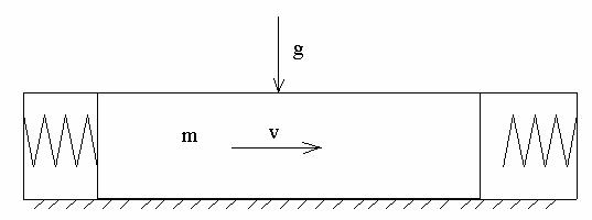
The alternating mass consists of the pistons, piston rings, piston pins, pin retainers, connecting rod, the moving components of the electric machine, and the fastener components. The forces acting on the translator are: inertial force, friction force, gas forces (compression and expansion), and load force. The linear engine can be thought of as a simple mass-spring system as shown in Figure 36. Figure 37 shows the free body diagram of the translator.
Figure 36. The linear engine can be thought of a mass spring system. The forces acting on the alternating mass (translator) define its motion.
70

Csaba Tóth-Nagy |
Linear Engine Development for Series Hybrid Electric Vehicles |
Figure 37 shows the free body diagram of the linear engine translator being driven
by expanding combustion gases.
Figure 37. The free body diagram of the linear engine. Gravity is represented by g and the reaction force is represented by R.
The mass represents the combined mass of the translator, the two springs represent the gas being compressed in the cylinders and the exciting force represents the gas forces during expansion or compression. The gap between the translator and the spring on the right hand side represents the range where ports are open in both cylinders at the same time. The exhaust port is already uncovered in the expansion cylinder, letting the expansion pressure blow-down. At the same time, ports are still uncovered in the compression cylinder therefore compression has not started yet. Only inertial, load, and friction forces act on the mass at this time. This is the free travel distance. As the force equilibrium defines it, the sum of the forces acting on the mass must be equal to zero.
Equation 1.
ΣF=0= Fi + Ff + Fl + Fc - Fe
71
Csaba Tóth-Nagy |
Linear Engine Development for Series Hybrid Electric Vehicles |
4.1.1 Inertial force
Newton’s second law of motion defines the inertial force based on the mass and the acceleration of the translator:
Equation 2.
Fi = m a
4.1.2 Friction force
A large amount of literature discusses the problem of friction in internal combustion engines in conventional rotating engines. Scientists have developed simplified friction models to simulate engine friction [110-113]. In a linear engine, the situation is already simplified compared to a rotating engine, because there is no crankshaft. Except for the effect of gravity (which is negligible compared to the side thrust in a slider-crank engine), there is no side thrust on the piston, therefore the piston does not move in the cylinder in radial direction. The sources of friction force in a linear engine are friction between the piston rings and the cylinder liner and friction between the piston skirt and the cylinder liner. A simple approach was chosen to model friction force in the simulation. Equation 3. shows the equation that was used to calculate friction force in the simulation. Vp represents the velocity of the translator and fd represents the friction coefficient.
Equation 3. |
|
Ff = fd Vp |
fd=f(bore, translator mass) |
The constant fd was the friction coefficient. It was represented as the function of bore size and translator mass. These two parameters were chosen because the size of the bore influences the friction caused by ring tension and the mass influences the friction
72