

CCNPv7 ROUTELab 4-1, Redistribution Between EIGRP and OSPF

CCNPv7 ROUTE
Chapter 4 Lab 4-1, Redistribution Between eigrp and ospf
Instructor Version
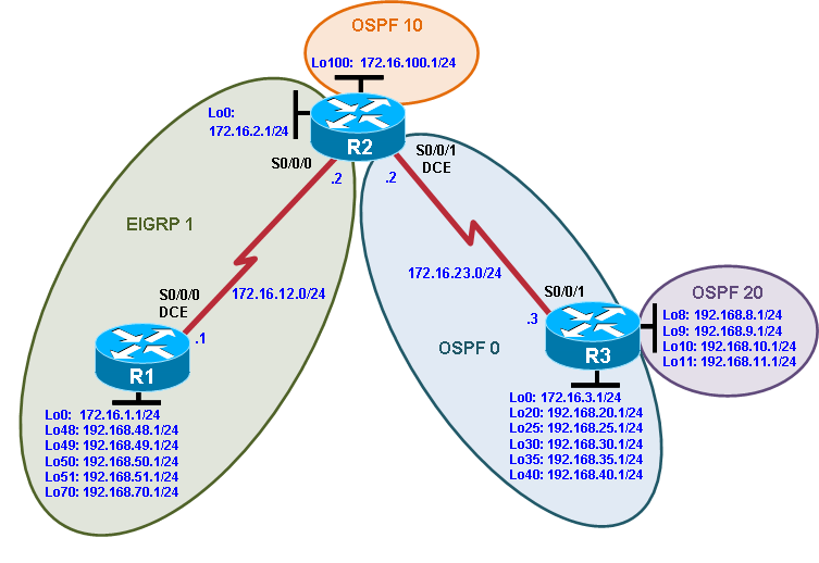
Topology
Objectives
Review EIGRP and OSPF configuration.
Summarize routes in EIGRP.
Summarize in OSPF at an ABR.
Redistribute into EIGRP.
Redistribute into OSPF.
Summarize in OSPF at an ASBR.
Background
Two online booksellers, Example.com and Example.net, have merged and now need a short-term solution to inter-domain routing. Since these companies provide client services to Internet users, it is essential to have minimal downtime during the transition.
Example.com is running EIGRP while Example.net is running a multi-area OSPF. Because it is imperative that the two booksellers continuously deliver Internet services, you should bridge these two routing domains without interfering with each router’s path through its own routing domain to the Internet.
The CIO determines that it is preferable to keep the two protocol domains shown in the diagram during the transition period, because the network engineers on each side need to understand the other’s network before deploying a long-term solution. Redistribution will be a short-term solution.
In this scenario, R1 and R2 are running EIGRP while R2 is the OSPF autonomous system border router (ASBR) consisting of areas 0, 10, and 20. You need to configure R2 to enable these two routing protocols to interact to allow full connectivity between all networks.
In this lab, R1 is running EIGRP and R3 is running multi-area OSPF. Your task is to configure redistribution on R2 to enable these two routing protocols to interact, allowing full connectivity between all networks.
Note:This lab uses Cisco 1941 routers with Cisco IOS Release 15.2 with IP Base.Depending on the router or switch model and Cisco IOS Software version, the commands available and output produced might vary from what is shown in this lab.
Required Resources
3 routers (CiscoIOS Release 15.2 or comparable)
Serial and Ethernet cables
Step 1: Configure loopbacks and assign addresses.
Configure all loopback interfaces on the three routers in the diagram. Configure the serial interfaces with the IP addresses, bring them up, and set a DCE clock rate where appropriate.
R1(config)# interface Loopback0
R1(config-if)# ip address 172.16.1.1 255.255.255.0
R1(config-if)# exit
R1(config)# interface Loopback48
R1(config-if)# ip address 192.168.48.1 255.255.255.0
R1(config-if)# exit
R1(config)# interface Loopback49
R1(config-if)# ip address 192.168.49.1 255.255.255.0
R1(config-if)# exit
R1(config)# interface Loopback50
R1(config-if)# ip address 192.168.50.1 255.255.255.0
R1(config-if)# exit
R1(config)# interface Loopback51
R1(config-if)# ip address 192.168.51.1 255.255.255.0
R1(config-if)# exit
R1(config)# interface Loopback70
R1(config-if)# ip address 192.168.70.1 255.255.255.0
R1(config-if)# exit
R1(config)# interface Serial0/0/0
R1(config-if)# ip address 172.16.12.1 255.255.255.0
R1(config-if)# clock rate 64000
R1(config-if)# bandwidth 64
R1(config-if)# no shutdown
R2(config)# interface Loopback0
R2(config-if)# ip address 172.16.2.1 255.255.255.0
R2(config-if)# exit
R2(config)# interface loopback 100
R2(config-if)# ip address 172.16.100.1 255.255.255.0
R2(config-if)# exit
R2(config)# interface Serial0/0/0
R2(config-if)# ip address 172.16.12.2 255.255.255.0
R2(config-if)# bandwidth 64
R2(config-if)# no shutdown
R2(config-if)# exit
R2(config)# interface Serial0/0/1
R2(config-if)# ip address 172.16.23.2 255.255.255.0
R2(config-if)# clock rate 64000
R2(config-if)# bandwidth 64
R2(config-if)# no shutdown
R3(config)# interface Loopback0
R3(config-if)# ipaddress 172.16.3.1 255.255.255.0
R3(config-if)# exit
R3(config)# interface loopback 8
R3(config-if)# ip address 192.168.8.1 255.255.255.0
R3(config-if)# exit
R3(config)# interface loopback 9
R3(config-if)# ip address 192.168.9.1 255.255.255.0
R3(config-if)# exit
R3(config)# interface loopback 10
R3(config-if)# ip address 192.168.10.1 255.255.255.0
R3(config-if)# exit
R3(config)# interface loopback 11
R3(config-if)# ip address 192.168.11.1 255.255.255.0
R3(config-if)# exit
R3(config)# interface Loopback20
R3(config-if)# ipaddress 192.168.20.1 255.255.255.0
R3(config-if)# exit
R3(config)# interface Loopback25
R3(config-if)# ip address 192.168.25.1 255.255.255.0
R3(config-if)# exit
R3(config)# interface Loopback30
R3(config-if)# ipaddress 192.168.30.1 255.255.255.0
R3(config-if)# exit
R3(config)# interface Loopback35
R3(config-if)# ip address 192.168.35.1 255.255.255.0
R3(config-if)# exit
R3(config)# interface Loopback40
R3(config-if)# ip address 192.168.40.1 255.255.255.0
R3(config-if)# exit
R3(config)# interface Serial0/0/1
R3(config-if)# ip address 172.16.23.3 255.255.255.0
R3(config-if)# bandwidth 64
R3(config-if)# no shutdown
Verify that you can ping across the serial links when you are finished. Use the following Tcl script to check full and partial connectivity throughout this lab.
R1# tclsh
foreach address {
172.16.1.1
192.168.48.1
192.168.49.1
192.168.50.1
192.168.51.1
192.168.70.1
172.16.12.1
172.16.12.2
172.16.2.1
172.16.100.1
172.16.23.2
172.16.23.3
172.16.3.1
192.168.8.1
192.168.9.1
192.168.10.1
192.168.11.1
192.168.20.1
192.168.25.1
192.168.30.1
192.168.35.1
192.168.40.1
} { ping $address }
Which pings are successful and why?
At this point, only directly connected interfaces will be successful. For example, R1 should be successfully pinging the first eight IP addresses (from 172.16.1.1 to 172.16.12.2) in the list and failing for all other IP addresses as they are not on directly connected networks.