- •Chapter 6 Lab 6-1, Configure nat Services
- •Required Resources
- •Step 1: Configure loopbacks and assign addresses.
- •Isp (r2)
- •209.165.200.241
- •209.165.202.129
- •209.165.200.226
- •Step 2: Configure default static routes on Branch and hq.
- •209.165.200.241
- •209.165.202.129
- •209.165.200.226
- •209.165.200.241
- •209.165.202.129
- •209.165.200.226
- •Step 4: Configure nat on the Branch router.
- •Step 5: Verify nat Configuration.
- •209.165.200.241
- •209.165.202.129
- •209.165.200.226
- •209.165.200.238
- •Device Configurations (Instructor version)
CCNPv7 ROUTELab 6-1, Configure NAT Services

CCNPv7 ROUTE
Chapter 6 Lab 6-1, Configure nat Services
Instructor Version
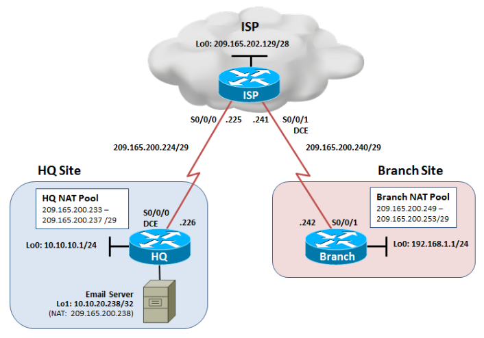
Topology

Objectives
Configure dynamic NAT and static NAT on the HQ router.
Configure dynamic NAT on the Branch router.
Verify the configuration and operation using showcommands.
Background
The HQ and Branch sites must be configured to support NAT. Specifically, the HQ and Branch routers will be configured to provide inside LAN users with outside public addresses using NAT. The HQ router will also provide static NAT to access the Email server from the outside network.
Note:This lab uses Cisco 1941 routers with Cisco IOS Release 15.2 with IP Base. Depending on the router or switch model and Cisco IOS Software version, the commands available and output produced might vary from what is shown in this lab.
Required Resources
3 routers (Cisco IOS Release 15.2 or comparable)
Serial and Ethernet cables
Step 1: Configure loopbacks and assign addresses.
Cable the network as shown in the topology diagram. Erase the startup configuration and reload each router to clear previous configurations. Using the addressing scheme in the diagram, apply the IP addresses to the interfaces on the HQ, ISP, and Branch routers.
You can copy and paste the following configurations into your routers to begin.
Note: Depending on the router model, interfaces might be numbered differently than those listed. You might need to alter the designations accordingly.
HQ (R1)
hostname HQ
!
interface Loopback0
description Headquarters LAN
ip address 10.10.10.1 255.255.255.0
exit
!
interface Loopback1
description Simulates the Email Server
ip address 10.10.20.238 255.255.255.255
exit
!
interface Serial0/0/0
description Connection to ISP
ip address 209.165.200.226 255.255.255.248
clock rate 128000
no shut
exit
!
end
Isp (r2)
hostname ISP
!
interface Loopback0
description Simulating the Internet
ip address 209.165.202.129 255.255.255.240
exit
!
interface Serial0/0/0
description Connection to HQ
ip address 209.165.200.225 255.255.255.248
no shut
exit
!
interface Serial0/0/1
description Connection to Branch
ip address 209.165.200.241 255.255.255.248
clock rate 128000
no shut
exit
!
ip route 209.165.200.232 255.255.255.248 Serial0/0/0
ip route 209.165.200.248 255.255.255.248 Serial0/0/1
!
end
Branch (R3)
hostname Branch
!
interface Loopback0
description Branch LAN
ip address 192.168.1.1 255.255.255.0
exit
!
interface Serial0/0/1
description Connection to ISP
ip address 209.165.200.242 255.255.255.248
no shut
exit
!
end
Verify your configuration by using the show ip interface briefand theshow interfaces descriptioncommand. The output from the Branch router is shown here as an example.
Branch# show ip interface brief | include up
Serial0/0/1 209.165.200.242 YES manual up up
Loopback0 192.168.1.1 YES manual up up
Branch#
Branch# show interfaces description | include up
Se0/0/1 up up Connection to ISP
Lo0 up up Branch LAN
Branch#
From the Branch router, run the following Tcl script to verify connectivity.
foreach address {
