

Davis W.A.Radio frequency circuit design.2001
.pdf
|
|
|
STABILITY OF AN OSCILLATOR |
211 |
|||
Zd(A,ω ) |
|
|
|
|
|
Z (ω) |
|
|
|
|
|
|
|
||
|
|
|
|
|
|
||
|
|
|
|
|
|
|
|
FIGURE 10.12 Oscillator model when the passive impedance Z ω is separated from the active device Zd A, ω .
Ordinarily the passive circuit selects the frequency of oscillation by means of a high-Q resonator. The relative frequency dependence of the active device is small, so Eq. (10.39) can be approximated by
Zd A C Z ω D 0 |
10.40 |
In phaser notation the current is |
|
I D Aej- |
10.41 |
and |
|
Z ω D R ω C jX ω |
10.42 |
so that the voltage drop around the closed loop in Fig. 10.12 is |
|
0D <f[Z ω C Zd A ]Ig
D [R ω C Rd A ]A cos ωt C - [X ω C Xd A ]A sin ωt C - 10.43
The time rate of change of the current is found by taking the derivative of Eq. (10.38):
di |
|
d- |
sin ωt C - C |
dA |
|
|||||||
|
D A |
ω C |
|
|
cos ωt C - |
|
||||||
dt |
dt |
dt |
|
|||||||||
|
|
|
|
d- |
|
1 dA |
|
|||||
|
|
j ω |
|
|
|
|
|
|
AejωtC- |
10.44 |
||
|
D < |
C dt |
|
|
||||||||
|
|
C A dt |
|
|||||||||
Ordinarily, in ac circuit analysis, d/dt is equivalent to jω in the frequency domain. Now, with variation in the amplitude and phase, the time derivative is equivalent to
d |
|
d- |
|
1 dA |
|
|||
|
! jω0 D j |
ω C |
|
j |
|
|
|
10.45 |
dt |
dt |
A |
dt |
|||||
The Taylor series expansion of Z ω0 about ω0 is
Z ω C |
d- 1 dA |
³ Z ω0 C |
dZ |
|
d- 1 dA |
10.46 |
||||||||
|
j |
|
|
|
|
|
|
j |
|
|
|
|||
dt |
A |
dt |
dω |
dt |
A |
dt |
||||||||

212 OSCILLATORS AND HARMONIC GENERATORS
Consequently an expression for the voltage around the closed loop can be found:
<f Z C Zd Ig D R ω0 C Rd A C |
dR d- dX 1 dA |
|
|
A cos ωt C - |
||||||||||||||||
|
|
|
|
C |
|
|
|
|
|
|
|
|
|
|||||||
dω |
dt |
dω |
A |
dt |
||||||||||||||||
X ω0 C Xd A C |
dX d- |
|
dR 1 dA |
A sin ωt C - |
||||||||||||||||
|
|
|
|
|
|
|
|
|||||||||||||
dω |
dt |
dω |
A |
dt |
||||||||||||||||
10.47
Multiplying Eq. (10.47) by cos ωt C - and then by sin ωt C - and finally integrating will produce, by the orthogonality property, the following two equations:
0 D R ω C Rd A C |
dR d- |
dX 1 dA |
10.48 |
|||||||||||||||||
|
|
|
|
|
|
C |
|
|
|
|
|
|
|
|
|
|
|
|||
dω |
dt |
dω |
A |
|
dt |
|||||||||||||||
0 D X ω Xd A |
dX d- |
|
dR 1 dA |
10.49 |
||||||||||||||||
|
|
|
C |
|
|
|
|
|
||||||||||||
dω |
dt |
dω |
A |
dt |
||||||||||||||||
Multiplying Eq. (10.48) by dX/dω and Eq. (10.49) by dR/dω and adding will eliminate the d-/dt term. A similar procedure will eliminate dA/dt. The result is
|
dX |
dZ ω 2 |
1 dA |
|
|||||||
0 D [R ω C Rd A ] |
|
|
|
[X ω C Xd A ] C |
|
|
|
|
|
|
10.50 |
dω |
dω |
A dt |
|||||||||
0 D [X ω C Xd A ] |
dX |
dZ ω 2 |
d- |
|
|||||||
|
C [R ω C Rd A ] C |
|
|
|
|
10.51 |
|||||
dω |
dω |
dt |
|||||||||
Under steady state conditions the time derivatives are zero. The combination of Eqs. (10.50) and (10.51) gives
dR/dω |
|
R ω C Rd A |
|
X ω C Xd A |
10.52 |
|
dX/dω |
D X ω C Xd A |
D R ω C Rd A |
||||
|
||||||
The only way for this equation to be satisfied results in Eq. (10.40). However, suppose that there is a small disturbance in the current amplitude of υA from the steady state value of A0. Based on Eq. (10.40) the resistive and reactive components would become
R ω0 C Rd A D R ω0 C Rd A0 C υA |
dRd A |
|
||
dA |
||||
D υA |
dRd A |
|
10.53 |
|
dA |
||||
X ω0 C Xd A D υA |
dXd A |
|
10.54 |
|
dA |
||||

STABILITY OF AN OSCILLATOR |
213 |
The derivatives are of course assumed to be evaluated at A D A0. Substituting these into Eq. (10.50) gives the following differential equation with respect to time:
0 DυA |
dRd A dX ω |
υA |
dXd A dR ω |
dZ ω 2 1 dυA |
10.55 |
|||||||||||||||||||||||||
|
|
|
|
|
|
|
|
|
|
|
|
|
|
|
|
|
|
|
|
C |
|
|
|
|
|
|||||
|
|
dA |
|
|
|
|
dω |
dA |
|
dω |
|
dω A0 dt |
||||||||||||||||||
|
|
|
|
dυA |
|
|
|
|
|
|
|
|
|
|
|
|
|
|
|
|
10.56 |
|||||||||
0 DυAS C ˛ |
dt |
|
|
|
|
|
|
|
|
|
|
|
|
|
|
|
|
|||||||||||||
or |
|
|
|
|
|
|
|
|
|
|
|
|
|
|
|
|
|
|
|
|
|
|
|
|
|
|
|
|
|
|
where |
|
|
|
|
|
|
|
|
|
|
|
|
|
|
|
|
|
|
|
|
|
|
|
|
|
|
|
|
|
|
∂Rd A dX ω |
|
∂Xd A dR ω |
> 0 |
|
|
|
|
|
10.57 |
|||||||||||||||||||||
S D |
|
|
|
|
|
|
|
|
|
|
|
|
|
|
|
|
|
|
|
|
|
|
|
|
||||||
|
|
∂A |
|
|
|
|
|
dω |
|
∂A |
|
|
|
dω |
|
|
|
|
|
|||||||||||
and |
|
|
|
|
|
|
|
|
|
|
|
|
|
|
|
|
|
|
|
|
|
|
|
|
|
|
|
|
|
|
|
|
|
dZ ω 2 1 |
|
|
|
|
|
|
|
|
|
|
|
|
|
|
|
|
10.58 |
||||||||||
˛ D |
|
|
|
|
|
|
|
|
|
|
|
|
|
|
|
|
|
|
|
|
|
|
|
|
|
|
|
|||
|
|
dω |
|
|
|
|
|
|
A0 |
|
|
|
|
|
|
|
|
|
|
|
|
|
|
|
|
|||||
The solution of Eq. (10.56) is |
|
|
|
|
|
|
|
|
|
|
|
|
|
|
|
|
|
|||||||||||||
|
|
|
|
|
|
|
|
|
|
|
|
|
|
υA |
D |
Ce St/˛ |
|
|
|
|
|
|
|
|
||||||
|
|
|
|
|
|
|
|
|
|
|
|
|
|
|
|
|
|
|
|
|
|
|
|
|
|
|
|
|
|
|
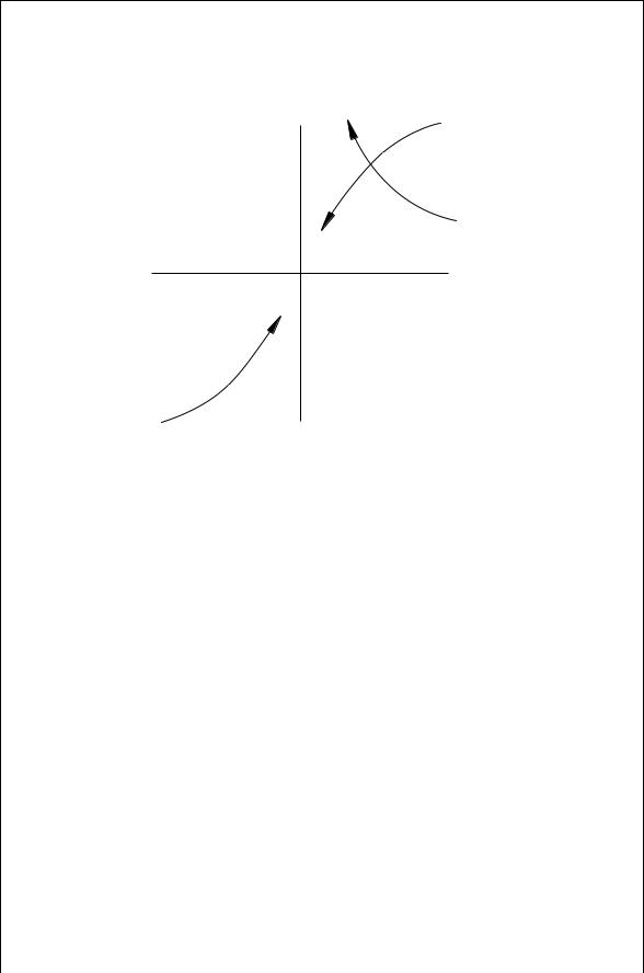
which is stable if S > 0. The Kurokawa stability condition for small changes in the current amplitude is therefore given by Eq. (10.57) [6]. As an example, consider the stability of a circuit whose passive circuit impedance changes with frequency as shown in Fig. 10.13 and whose device impedance changes with current amplitude as shown in the third quadrant of Fig. 10.13. As the current amplitude increases, Rd A and Xd A both increase:
∂Rd A
> 0
∂A
∂Xd A
> 0
∂A
As frequency increases, the passive circuit resistance, R ω , decreases and the circuit reactance, X ω , increases:
∂R ω
< 0
∂ω
∂X ω
> 0
∂ω
From Eq. (10.57) this would provide stable oscillations at the point where Z ω and Zd A intersect. If there is a small change in the current amplitude, the circuit tends to return back to the A0, ω0 resonant point.
214 OSCILLATORS AND HARMONIC GENERATORS
Z (ω) |
–Z d (0) |
X |
|
Z (0)
–Z d(A )
R
+Z d(A )
+Z d (0)
FIGURE 10.13 Locus of points for the passive and active oscillator impedances.
If there is a small perturbation in the phase rather than the amplitude of the of the current, the stability criterion is
S0 |
∂Xd - dX ω |
|
∂Xd - dR ω |
> 0 |
10.59 |
|||||
D |
|
|
|
C |
|
|
|
|||
∂- dω |
∂- dω |
|||||||||
This is found by substituting into Eq. (10.51) with the appropriate Taylor series approximation for a change in phase.
10.8INJECTION-LOCKED OSCILLATORS
A free running oscillator frequency can be modified by applying an external frequency source to the oscillator. Such injection-locked oscillators can be used as high-power FM amplifiers when the circuit Q is sufficiently low to accommodate the frequency bandwidth of the signal. If the injection signal voltage, V, is at a frequency close to but not necessarily identical to the free running frequency of the oscillator, is placed in series with the passive impedance, Z ω , in Fig. 10.12, then the loop voltage is
[Z ω C Zd A ]I D V |
10.60 |


216 OSCILLATORS AND HARMONIC GENERATORS
will change its orientation as the injection frequency changes (thereby changing Z ω ). However, there is a limit to how much the jVj/A0 vector can move because circuit and device impedances grow too far apart. In that case the injection lock ceases. The example in Fig. 10.14 is illustrated the simple series-resonant cavity where the circuit resistance is independent of frequency. Furthermore the jVj/A0 vector is drawn at the point of maximum frequency excursion from ω0. Here jVj/A0 is orthogonal to the Zd A line. If the frequency moves beyond ω1 or ω2, the oscillator loses lock with the injected signal. At the maximum locking frequency,
j |
2 ω |
m |
L cos 2 |
j D |
jVj |
10.64 |
|
A0 |
|||||||
|
|
|
The expressions for the oscillator power delivered to the load, P0, the available injected power, and the external circuit Qext are
P0 D |
1 |
RLA02 |
10.65 |
|||
2 |
||||||
P |
jVj2 |
|
10.66 |
|||
8RL |
||||||
i D |
|
|||||
Qext ³ |
ω0L |
10.67 |
||||
RL |
|
|||||
When these are substituted into Eq. (10.64), the well-known injection locking range is found [7]:
ωm D |
ω0 |
|
Pi 1 |
10.68 |
||
|
|
|
|
|
||
Qext |
|
P0 cos 2 |
||||
The total locking range is from ω0 C ωm to ω0 ωm. The expression originally given by Adler [8] did not included the cos 2 term. However, highfrequency devices often exhibit a phase delay of the RF current with respect to the voltage. This led to Eq. (10.68) where the device and circuit impedance lines are not necessarily orthogonal [7]. In the absence of information about the value of 2, a conservative approximation for the injection range can be made by choosing cos 2 D 1. The frequency range over which the oscillator frequency can be pulled from its free-running frequency is proportional to the square root of the injected power and inversely proportional to the circuit Q as might be expected intuitively.
10.9HARMONIC GENERATORS
The nonlinearity of a resistance in a diode can be used in mixers to produce a sum and difference of two input frequencies (see Chapter 11). If a large signal is applied to a diode, the nonlinear resistance can produce harmonics of the input

HARMONIC GENERATORS |
217 |
voltage. However, the efficiency of the nonlinear resistance can be no greater than 1/n, where n is the order of the harmonic. Nevertheless, a reverse-biased diode has a depletion elastance (reciprocal capacitance) given by
dv |
|
v |
5 |
|
D S D S0 1 |
|
10.69 |
dq |
- |
where - is the built-in voltage and typically is between 0.5 and 1 volt positive. The applied voltage v is considered positive when the diode is forward biased. The exponent 5 for a varactor diode typically ranges from 0 for a step recovery diode to 13 for a graded junction diode to 12 for an abrupt junction diode. Using the nonlinear capacitance of a diode theoretically allows for generation of harmonics with an efficiency of 100% with a loss free diode. This assertion is supported by the Manley-Rowe relations which describe the power balance when two frequencies, f1 and f2, along with their harmonics are present in a lossless circuit:
1 |
|
1 |
mPm,n |
D 0 |
10.70 |
|
m |
D |
0 n |
D 1 |
mf1 C nf2 |
||
|
|
|
|
|
||
1 |
|
1 |
nPm,n |
D 0 |
10.71 |
|
n 0 m |
D 1 |
mf1 C nf2 |
||||
D |
|
|
|
|
||
These equations are basically an expression of the conservation of energy. From (10.70)
1 |
|
P1 D Pm,0, n D 0 |
10.72 |
mD2 |
|
The depletion elastance given by Eq. (10.69) is valid for forward voltages up to about v/- D 12 . Under forward bias, the diode will tend to exhibit diffusion capacitance that tends to be more lossy in varactor diodes than the depletion capacitance associated with reverse-biased diodes. Notwithstanding these complexities, an analysis of harmonic generators will be based on Eq. (10.69) for all applied voltages up to v D -. This is a reasonably good approximation when the minority carrier lifetime is long relative to the period of the oscillation. The maximum elastance (minimum capacitance) will occur at the reverse break down voltage, VB. The simplified model for the diode then is defined by two voltage ranges:
S |
|
- v |
5 |
|
|
|
|
|
D |
, |
v |
|
- |
10.73 |
|||
Smax |
- VB |
|||||||
|
|
|
|
|||||
S |
D 0, |
v > - |
|
|
|
10.74 |
||
|
|
|
|
|||||
Smax |
|
|
|
|||||

