

- •1. TABLE OF CONTENTS
- •2. BASIC MANUFACTURING
- •2.1 INTRODUCTION
- •2.2 PRACTICE PROBLEMS
- •3. MANUFACTURING COST ESTIMATING
- •3.1 COSTS ESTIMATES
- •3.2 COGS (COST OF GOODS SOLD)
- •3.3 VALUE ENGINEERING
- •3.4 REFERENCES
- •4. BASIC CUTTING TOOLS
- •4.1 CUTTING SPEEDS, FEEDS, TOOLS AND TIMES
- •4.2 HIGH SPEED MACHINING
- •4.3 REFERENCES
- •5. CUTTING THEORY
- •5.1 CHIP FORMATION
- •5.2 THE MECHANISM OF CUTTING
- •5.2.1 Force Calculations
- •5.2.1.1 - Force Calculations
- •5.2.1.2 - Merchant’s Force Circle With Drafting (Optional)
- •5.3 POWER CONSUMED IN CUTTING
- •5.4 PRACTICE QUESTIONS
- •5.5 TEMPERATURES IN CUTTING
- •5.6 TOOL WEAR
- •5.7 CUTTING TOOL MATERIALS
- •5.7.1 A Short List of Tool Materials
- •5.8 TOOL LIFE
- •5.8.1 The Economics of Metal Cutting
- •5.9 REFERENCES
- •5.10 PRACTICE PROBLEMS
- •6. SAWS
- •6.1 SPEEDS AND FEEDS
- •6.2 PRACTICE PROBLEMS
- •7. DRILLING
- •7.1 TYPES OF DRILL PRESSES
- •7.2 TYPICAL DRILL PRESS OPERATIONS
- •7.3 TYPICAL DRILL BITS
- •7.3.1 Reamers
- •7.3.2 Boring
- •7.3.3 Taps
- •7.4 DRILLING PROCESS PARAMETERS
- •7.4.1 The mrr For Drilling
- •7.5 PRACTICE PROBLEMS
- •8. LATHES
- •8.1 INTRODUCTION
- •8.2 OPERATIONS ON A LATHE
- •8.2.1 Machine tools
- •8.2.1.1 - Production Machines
- •8.3 LATHE TOOLBITS
- •8.3.1 Thread Cutting On A Lathe
- •8.3.2 Cutting Tapers
- •8.3.3 Turning Tapers on Lathes
- •8.4 FEEDS AND SPEEDS
- •8.4.1 The mrr for Turning
- •8.4.2 Process Planning for Turning
- •8.5 PRACTICE PROBLEMS
- •9. MILLING
- •9.1 INTRODUCTION
- •9.1.1 Types of Milling Operations
- •9.1.1.1 - Arbor Milling
- •9.1.2 Milling Cutters
- •9.1.3 Milling Cutting Mechanism
- •9.1.3.1 - Up-Cut Milling
- •9.1.3.2 - Down-Cut Milling
- •9.2 FEEDS AND SPEEDS
- •9.2.1 The mrr for Milling
- •9.2.2 Process Planning for Prismatic Parts
- •9.2.3 Indexing
- •9.3 PRACTICE PROBLEMS
- •10. GRINDING
- •10.1 OPERATIONS
- •10.2 MACHINE TYPES
- •10.2.1 Surface
- •10.2.2 Center
- •10.2.3 Centerless
- •10.2.4 Internal
- •10.3 GRINDING WHEELS
- •10.3.1 Operation Parameters
- •10.4 PRACTICE PROBLEMS
- •11. SURFACES
- •11.1 MEASURES OF ROUGHNESS
- •11.2 METHODS OF MEASURING SURFACE ROUGHNESS
- •11.2.1 Observation Methods
- •11.2.2 Stylus Equipment
- •11.2.3 Specifications on Drawings
- •11.3 OTHER SYSTEMS
- •11.4 PRACTICE PROBLEMS
- •11.4.0.1 - Roundness Testing
- •11.4.0.1.1 - Intrinsic Roundness Testing
- •11.4.0.1.2 - Extrinsic Roundness Testing
- •11.4.0.1.3 - Practice Problems
- •11.5 PRACTICE PROBLEMS
- •35. METROLOGY
- •35.1 INTRODUCTION
- •35.1.1 The Role of Metrology
- •35.2 DEFINITIONS
- •35.3 STANDARDS
- •35.3.1 Scales
- •35.3.2 Calipers
- •35.3.3 Transfer Gauges
- •35.4 INSTRUMENTS
- •35.4.1 Vernier Scales
- •35.4.2 Micrometer Scales
- •35.4.2.1 - The Principle of Magnification
- •35.4.2.2 - The Principle of Alignment
- •35.4.3 Dial Indicators
- •35.4.4 The Tool Makers Microscope
- •35.4.5 Metrology Summary
- •35.5 PRACTICE PROBLEMS
- •35.5.0.1 - Interferometry (REWORK)
- •35.5.0.1.1 - Light Waves and Interference
- •35.5.0.1.2 - Optical Flats
- •35.5.0.1.3 - Interpreting Interference Patterns
- •35.5.0.1.4 - Types of Interferometers
- •35.5.0.2 - Laser Measurements of Relative Distance
- •35.5.0.2.1 - Practice Problems
- •35.6 GAUGE BLOCKS
- •35.6.1 Manufacturing Gauge Blocks
- •35.6.2 Compensating for Temperature Variations
- •35.6.2.1 - References
- •35.6.3 Testing For Known Dimensions With Standards
- •35.6.3.1 - References
- •35.6.4 Odd Topics
- •35.6.5 Practice Problems
- •35.6.6 Limit (GO & NO GO) Gauges
- •35.6.6.1 - Basic Concepts
- •35.6.6.2 - GO & NO GO Gauges Using Gauge Blocks
- •35.6.6.3 - Taylor’s Theory for Limit Gauge Design
- •35.6.6.4.1 - Sample Problems
- •35.6.7 Sine Bars
- •35.6.7.1 - Sine Bar Limitations
- •35.6.7.1.1 - Practice Problems
- •35.6.8 Comparators
- •35.6.8.1 - Mechanical Comparators
- •35.6.8.2 - Mechanical and Optical Comparators
- •35.6.8.3 - Optical Comparators
- •35.6.8.4 - Pneumatic Comparators
- •35.6.9 Autocollimators
- •35.6.10 Level Gauges
- •35.6.10.1 - Clinometer
- •35.6.10.2 - The Brookes Level Comparator
- •35.6.11 The Angle Dekkor
- •35.7 MEASURING APARATUS
- •35.7.1 Reference Planes
- •35.7.1.1 - Granite Surface Plates
- •35.7.1.2 - Cast Iron Surface Plates
- •35.7.2 Squares
- •35.7.2.1 - Coordinate Measureing Machines
- •35.7.2.2 - Practice Problems
- •AM:35.7.3 Coordinate Measuring Machines (CMM)
- •36. ASSEMBLY
- •36.1 THE BASICS OF FITS
- •36.1.1 Clearance Fits
- •36.1.2 Transitional Fits
- •36.1.3 Interference Fits
- •36.2 C.S.A. B97-1 1963 LIMITS AND FITS(REWORK)
- •36.3 CSA MODIFIED FITS
- •36.4 CSA LIMITS AND FITS
- •36.5 THE I.S.O. SYSTEM
- •36.6 PRACTICE PROBLEMS
- •42. WELDING/SOLDERING/BRAZING
- •42.1 ADHESIVE BONDING
- •42.2 ARC WELDING
- •42.3 GAS WELDING
- •42.4 SOLDERING AND BRAZING
- •42.5 TITANIUM WELDING
- •42.5.1 Practice Problems
- •42.6 PLASTIC WELDING
- •42.7 EXPLOSIVE WELDING
- •42.7.1 Practice Problems
- •43. AESTHETIC FINISHING
- •43.1 CLEANING AND DEGREASING
- •43.2 PAINTING
- •43.2.1 Powder Coating
- •43.3 COATINGS
- •43.4 MARKING
- •43.4.1 Laser Marking
- •43.5 PRACTICE PROBLEMS
- •44. METALLURGICAL TREATMENTS
- •44.1 HEAT TREATING
- •44.2 ION NITRIDING
- •44.3 PRACTICE PROBLEMS
- •45. CASTING
- •45.1 SAND CASTING
- •45.1.1 Molds
- •45.1.2 Sands
- •45.2 SINGLE USE MOLD TECHNIQUES
- •45.2.1 Shell Mold Casting
- •45.2.2 Lost Foam Casting (Expandable Pattern)
- •45.2.3 Plaster Mold Casting
- •45.2.4 Ceramic Mold Casting
- •45.2.5 Investment Casting
- •45.3 MULTIPLE USE MOLD TECHNIQUES
- •45.3.1 Vacuum Casting
- •45.3.2 Permanent Mold Casting
- •45.3.2.1 - Slush Casting
- •45.3.2.2 - Pressure Casting
- •45.3.2.3 - Die Casting
- •45.3.3 Centrifugal Casting
- •45.3.4 Casting/Forming Combinations
- •45.3.4.1 - Squeeze Casting
- •45.3.4.2 - Semisolid Metal Forming
- •45.3.5 Single Crystal Casting
- •45.4 OTHER TOPICS
- •45.4.1 Furnaces
- •45.4.2 Inspection of Casting
- •45.5 Design of Castings
- •45.6 REFERENECES
- •45.7 PRACTICE PROBLEMS
- •46. MOLDING
- •46.1 REACTION INJECTION MOLDING (RIM)
- •46.1.1 References
- •46.2 INJECTION MOLDING
- •46.2.1 Hydraulic Pumps/Systems
- •46.2.2 Molds
- •46.2.3 Materials
- •46.2.4 Glossary
- •46.3 EXTRUSION
- •46.4 PRACTICE PROBLEMS
- •47. ROLLING AND BENDING
- •47.1 BASIC THEORY
- •47.2 SHEET ROLLING
- •47.3 SHAPE ROLLING
- •47.4 BENDING
- •48. SHEET METAL FABRICATION
- •48.1 SHEET METAL PROPERTIES
- •48.2 SHEARING
- •48.2.1 Progressive and Transfer Dies
- •48.2.2 DRAWING
- •48.3 DEEP DRAWING
- •48.4 SPINNING
- •48.5 MAGNETIC PULSE FORMING
- •48.6 HYDROFORMING
- •48.7 SUPERPLASTIC FORMING
- •48.7.1 Diffusion Bonding
- •48.8 PRACTICE PROBLEMS
- •49. FORGING (to be expanded)
- •49.1 PROCESSES
- •49.1.1 Open-Die
- •49.1.2 Impression/Closed Die
- •49.1.3 Heading
- •49.1.4 Rotary Swaging
- •50. EXTRUSION AND DRAWING
- •50.1 DIE EXTRUSION
- •50.1.1 Hot Extrusion
- •50.1.2 Cold Extrusion
- •50.2 HYDROSTATIC EXTRUSION
- •50.3 DRAWING
- •50.4 EQUIPMENT
- •50.5 PRACTICE PROBLEMS
- •51. ELECTROFORMING
- •51.1 PRACTICE PROBLEMS
- •52. COMPOSITE MANUFACTURING
- •52.1 FIBER REINFORCED PLASTICS (FRP)
- •52.2 COMPOSITE MANUFACTURING
- •52.2.1 Manual Layup
- •52.2.2 Automated Tape Lamination
- •52.2.3 Cutting of Composites
- •52.2.4 Vacuum Bags
- •52.2.5 Autoclaves
- •52.2.6 Filament Winding
- •52.2.7 Pultrusion
- •52.2.8 Resin-Transfer Molding (RTM)
- •52.2.9 GENERAL INFORMATION
- •52.2.10 REFERENCES
- •52.2.11 PRACTICE PROBLEMS
- •53. POWDERED METALLURGY
- •53.1 PRACTICE PROBLEMS
- •54. ABRASIVE JET MACHINING (AJM)
- •54.1 REFERENCES
- •54.2 PRACTICE PROBLEMS
- •55. HIGH PRESSURE JET CUTTING
- •56. ABRASIVE WATERJET CUTTING (AWJ)
- •57. ULTRA SONIC MACHINING (USM)
- •57.1 REFERENCES
- •57.1.1 General Questions
- •58. ELECTRIC DISCHARGE MACHINING (EDM)
- •58.1 WIRE EDM
- •58.2 PRACTICE PROBLEMS
- •58.3 REFERENCES
- •59. ELECTROCHEMICAL MACHINING (ECM)
- •59.1 REFERENCES
- •59.2 PRACTICE PROBLEMS
- •60. ELECTRON BEAM MACHINING
- •60.1 REFERENCES
- •60.2 PRACTICE PROBLEMS
- •61. ION IMPLANTATION
- •61.1 THIN LAYER DEPOSITION
- •61.2 PRACTICE PROBLEMS
- •62. ELECTROSTATIC SPRAYING
- •62.1 ELECTROSTATIC ATOMIZATION METHOD
- •62.2 PRACTICE PROBLEMS
- •63. AIR-PLASMA CUTTING
- •63.1 REFERENCES
- •63.2 PRACTICE PROBLEMS
- •64. LASER CUTTING
- •64.1 LASERS
- •64.1.1 References
- •64.2 LASER CUTTING
- •64.2.1 References
- •64.3 PRACTICE PROBLEMS
- •65. RAPID PROTOTYPING
- •65.1 STL FILE FORMAT
- •65.2 STEREOLITHOGRAPHY
- •65.2.1 Supports
- •65.2.2 Processing
- •65.2.3 References
- •65.3 BONDED POWDERS
- •65.4 SELECTIVE LASER SINTERING (SLS)
- •65.5 SOLID GROUND CURING (SGC)
- •65.6 FUSED DEPOSITION MODELLING (FDM)
- •65.7 LAMINATE OBJECT MODELING (LOM)
- •65.8 DIRECT SHELL PRODUCTION CASTING (DSPC)
- •65.9 BALLISTIC PARTICLE MANUFACTURING (BPM)
- •65.9.1 Sanders Prototype
- •65.9.2 Design Controlled Automated Fabrication (DESCAF)
- •65.10 COMPARISONS
- •65.10.1 References
- •65.11 AKNOWLEDGEMENTS
- •65.12 REFERENCES
- •65.13 PRACTICE PROBLEMS
- •66. PROCESS PLANNING
- •66.1 TECHNOLOGY DRIVEN FEATURES
- •66.2 MOST SIGNIFICANT FEATURE FIRST
- •66.3 DATABASE METHODS
- •66.4 MANUFACTURING VOLUMES
- •66.5 STANDARD PARTS
- •66.6 PRACTICE PROBLEMS
- •66.6.1 Case Study Problems
- •66.6.1.1 - Case 1
- •66.7 REFERENCES

page 268
46.1 REACTION INJECTION MOLDING (RIM)
• Basic Principle - A mold is brought together, and a multipart thermosetting polymer is mixed and injected. After the part sets, the mold is opened, and the part is removed. Post curing may be used.
|
recirculation lines |
component A |
component B |
|
mixing head |
|
(pull back to |
|
mix and mold) |
|
precise heaters |
|
large volume |
|
capacity pumps |
M |
M |
This way to mold
page 269
Component A
Component B
•Features:
-Very little energy is required, most energy is provided by the chemical reaction.
-Parts up to 100 lb produced.
-Surfaces don’t have flow lines found in traditional injection moulding.
-RIM materials tend to be low weight, corrosion resistant, and variable properties can be obtained by additives and ratio adjustment.
-RIM machines use lower pressures, and are therefore less expensive.
-Typical parts are; bus bumpers, large electronics cases, shoes, etc.
-Fillers can be used to increase strength.
-The basic process involves mixing the raw components.

page 270
Synchronized metering units
Isocyanate or
Prepolymer 

 mixing chamber
Pour
Polyol Mix
Mold
Preparation
Cure
Demold
Optional
Components
After process operations
•Metering and mixing are critical
-special metering pumps are required for the components to maintain material properties.
Fluid In
Normally closed inlet valve
Fluid Out
piston
Normally Closed Valve
In this common form of piston pump, the piston rod is drawn back creating suction that holds the valve closed, and pulls fluid into the chamber. When the cylinder is full of fluid
the piston motion is reversed, creating a pressure, and forcing the inlet vale closed, and the outlet valve open, and the
fluid is pumped out. The fluid volume can be controlled by using the cylinder size, and piston strokes
- mixing must thoroughly mix the components at high speed, and inject them without becoming clogged when the mixture sets.
|
page 271 |
|
|
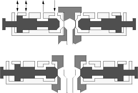
component |
component |
component |
component |
A |
B |
A |
B |
pump/tank |
pump/tank |
pump/tank |
pump/tank |
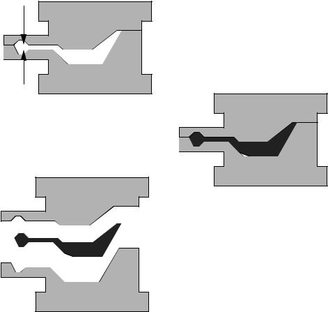
Mixing head is advanced, and the two components are mixed, and they pour into the mold
The two component have been mixed, or the mold is empty, and the mixing head is retracted, allowing the components to recirculate
• While the previous mix head is for a runnerless system, it is also common to have an extra component that is between the mix head and the part (the runner).
page 272
component is Hydraulic pumped in here fluid actuates
•An aftermix may also be used to increase mixing. A typical design will split the stream and cause it to impinge at 180°, then continue on to the mold.
•A comparison of the materials shows the advantages over a similar injection molded material.