


page 148
• Angular vernier scales are used on protractors, and are identical in use to linear vernier scales. The major protractor scales have divisions of 1 degree, and the vernier scale is divided into 5 minute intervals. One interesting note is that the vernier scale has two halves, one in the positive direction, and one in the negative direction. If reading from the left division, on the main scale, the right vernier scale should be used. And, when measuring from the right hand division on the major scale, the left vernier scale should be used.
35.4.2 Micrometer Scales
•This is a very common method for measuring instruments, and is based on the thread principle.
•In effect, as a thread is turned, a large motion on the outside of the thread will result in a very small advance in the position of the thread.
|
|
|
0.459 |
|
|
|
|
|
|
|
|
|
|
|
12 |
|
|
0 |
1 |
2 |
3 |
4 |
5 |
11 |
|
Imperial (Inches) |
|
10 |
|||||||
|
|
|
|
|
|
9 |
|
|
|
|
|
|
|
|
|
|
|
|
|
|
|
|
|
8 |
|
|
|
|
|
|
|
|
7 |
|
|
|
|
|
|
|
|
6 |
|
|
|
|
|
13.1 |
|
40 |
|
|
|
|
|
|
|
|
|
|
|
|
0 |
5 |
|
10 |
|
15 |
35 |
|
Metric |
|
|
|
|
|
|
30 |
|
|
|
|
|
|
|
|
|
|
|
|
|
|
|
|
|
25 |
|
|
•The micrometers pictured above have major scales, as well as minor scales. The major scales are read first, and the micrometer scales are read second and the readings added on.
•The metric micrometer above reads 13.5 = 13.5mm on the major scale, and 31 = .31mm on the thimble, for a total of 13.81mm
•The Imperial scale above shows a micrometer reading of 4.5 = .45” on the main scale, and 9 =
.009” on the thimble, for a total of .459
•On imperial micrometers the divisions are typically .025” on the sleeve, and 0.001” on the thimble. The thread used has 40 T.P.I. = a pitch of 0.025”
page 149
•Metric micrometers typically have 1 and 0.5 mm divisions on the sleeve, and 0.01mm divisions on the thimble. The thread has a pitch of 0.5mm.
•A vernier micrometer has the scales as pictured above, but also a vernier scale is included to provide another place of accuracy.
•Depth micrometers have an anvil that protrudes, out the end, and as a result the scales are reversed to measure extension, instead of retraction.
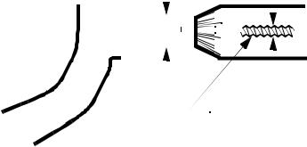
35.4.2.1 - The Principle of Magnification
•The operation of micrometers is based on magnification using threads.
•A large movement on the outside of the micrometer thimble will result in a small motion of the anvil.
•There are two factors in this magnification. First, the difference in radius between the thread, and the thimble will give a change in sensitivity relative to the difference in radii. Second, the pitch of the thread will provide a reduction in motion.
•The basic relationship can be seen below,
page 150
C π D M = --- ------------
D pitch
where,
M = magnification from the moving head to the hand motion C = measuring diameter of the instrument
D = diameter of the thread
pitch = the number of threads per unit length
Radial Arm Principle of Magnification = |
C |
|
|
|
|
|
|
|
|
|
|
|
|
|
|
|
|
|
|
|
|
|
|
|
|
|
|
|
|
|
|
|
|
|
|
|
|
|
|
|
|
|
|||
--- |
|
|
|
|
|
|
|
|
|
|
|
|
|
|
|
|
|
|
|
|
|
|
|
|
|
|
|
|
|
|
|
|
|
|
|
|
|
|
|
|
|
||||
|
|
|
|
D |
|
|
|
|
|
|
|
|
|
|
|
|
|
|
|
|
|
|
|
|
|
|
|
|
|
|
|
|
|
|
|
|
|
|
|
|
|
|
|
|
|
Inclined Plane Principle of Magnification |
= |
π |
|
D |
|
|
|
|
|
|
|
|
|
|
|
|
|
|
|
|
|
|
|
|
|
||||||||||||||||||||
------------ |
|
|
|
|
|
|
|
|
|
|
|
|
|
|
|
|
|
|
|
|
|
|
|
|
|
|
|
||||||||||||||||||
|
|
|
|
|
pitch |
|
|
|
|
|
|
|
|
|
|
|
|
|
|
|
|
|
|
|
|
|
|||||||||||||||||||
|
|
|
|
|
|
|
|
|
|
|
|
|
|
|
|
|
|
|
|
|
|
|
|
|
C |
|
|
|
|
|
|
|
|
D |
|
||||||||||
NOTE: magnification |
|
|
|
|
|
|
|
|
|
|
|
|
|
|
|
|
|
|
|
|
|
|
|
|
|
|
|
|
|
|
|
|
|
||||||||||||
|
|
|
|
|
|
|
|
|
|
|
|
|
|
|
|
|
|
|
|
|
|
|
|
|
|
|
|
|
|
|
|
|
|
||||||||||||
can result in greater |
|
|
|
|
|
|
|
|
|
|
|
|
|
|
|
|
|
|
|
|
|
|
|
|
|
|
|
|
|
|
|
|
|
|
|
|
|
|
|
|
|
|
40 |
|
|
|
|
|
|
|
|
|
|
|
|
|
|
|
|
|
|
|
|
|
|
|
|
|
|
|
|
|
|
|
|
|
|
|
|
|
|
|
|
|
|
|
|
|
|
||
|
|
|
|
|
|
|
|
|
|
|
|
|
|
|
|
|
|
|
|
|
|
|
|
|
|
|
|
|
|
|
|
|
|
|
|
|
|
|
|
35 |
|
|
|||
|
0 |
|
|
|
|
|
|
|
|
|
|
|
5 |
|
|
|
|
|
|
|
|
|
10 |
|
|
|
|
|
|
15 |
|
|
|
|
|
|
|
|
|||||||
sensitivity of an |
|
|
|
|
|
|
|
|
|
|
|
|
|
|
|
|
|
|
|
|
|
|
|
|
|
|
|
|
|
|
|
|
|
|
|
|
|
|
|||||||
|
|
|
|
|
|
|
|
|
|
|
|
|
|
|
|
|
|
|
|
|
|
|
|
|
|
|
|
|
|
|
|
|
|
|
|
|
|
|
|
|
|
30 |
|
|
|
|
|
|
|
|
|
|
|
|
|
|
|
|
|
|
|
|
|
|
|
|
|
|
|
|
|
|
|
|
|
|
|
|
|
|
|
|
|
|
|
|
|
|
|||
insrument to control, |
|
|
|
|
|
|
|
|
|
|
|
|
|
|
|
|
|
|
|
|
|
|
|
|
|
|
|
|
|
|
|
|
|
|
|
|
|
|
|
|
|
|
|
|
|
|
|
|
|
|
|
|
|
|
|
|
|
|
|
|
|
|
|
|
|
|
|
|
|
|
|
|
|
|
|
|
|
|
|
|
|
|
|
|
|
25 |
|
|
|||
|
|
|
|
|
|
|
|
|
|
|
|
|
|
|
|
|
|
|
|
|
|
|
|
|
|
|
|
|
|
|
|
|
|
|
|
|
|
|
|
|
|||||
and reading by a |
|
|
|
|
|
|
|
|
|
|
|
|
|
|
|
|
|
|
|
|
|
|
|
|
|
|
|
|
|
|
|
|
|
|
|
|
|
|
|
|
|
||||
|
|
|
|
|
|
|
|
|
|
|
|
|
|
|
|
|
|
|
|
|
|
|
|
|
|
|
|
|
|
|
|
|
|
|
|
|
|
|
|
|
|
|
|||
user. |
|
|
|
|
|
|
|
|
|
|
|
|
|
|
|
|
|
|
|
|
|
|
|
|
|
|
|
|
|
|
|
|
|
|
|
|
|
|
|
|
|
|
|
||
|
|
|
|
|
|
|
|
|
|
|
|
|
|
|
|
|
|
|
|
|
|
|
|
|
|
|
|
|
|
|
|
|
|
|
|
|
|
|
|
|
|
||||
|
|
|
|
|
|
|
|
|
|
|
|
|
|
|
|
|
|
|
|
|
|
|
|
|
|
|
|
|
|
|
|
|
|
|
|
|
|
pitch |
|
||||||
|
|
|
|
|
|
|
|
|
|
|
|
|
|
|
|
|
|
|
|
|
|
|
|
|
|
|
|
|
|
|
|
|
|
|
|
|
|
|
|
|
|
|
|
|
|
35.4.2.2 - The Principle of Alignment
•Basically, the line of the physical measurement should be such that it is coincident with the measurement axis of the instrument.
•If the measurement is out of line, it may lead to misreadings caused by deflections in the instrument.