

page 229
3. as the probe is moved over the weld, sparks will jump when a gap in the weld moves between the probe and the ground plate.
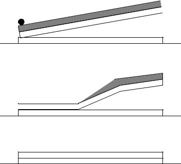
42.7 EXPLOSIVE WELDING
• The basic mechanism is based on molecular bonding, as a result of high velocity impact. The high velocities are promoted by carefully detonated explosives.
detonator |
explosive |
cladding plate
parent plate
anvil/ground
•The process is done at room temperature in air, water or vacuum.
•Surface contaminants tend to be blown off the surface.
•Typical impact pressures are millions of psi.
•The process can be done in vacuum to reduce sound and blast.
•Well suited to metals that are prone to brittle joints when heat welded, such as,
-aluminum on steel
-titanium on steel
•The process does not work well for,
-brittle metals with <5% tensile elongation
-Charpy V-notch value < 10 ft.lb.

page 230
•If two materials can be brought close enough together, they will bond at a molecular level.
•This normally does not happen because surface contaminants (ie oxides, nitrides and absorbed gases) prevent a close approach of surfaces.
•Normal welding overcomes this problem by melting materials so that they mix in liquid phases.
•Important factors are,
-critical velocity
-critical angle
cladding plate
 alpha
alpha
slag jet
|
|
|
|
|
point of bonding |
backer plate |
|
|
|||
•When parameters match up, the surfaces form a liquid jet starting at the point they impact, and is directed away from the welded seam.
•The plates have an airgap between, and plastic, liquid or granular explosives are placed on the plate. The backer plate is rested on an anvil (eg sand could be used for lighter backers, or concrete/steel for stronger backers).
•The cladding plate can be supported with tack welded supports at the edges, or the metal inserts.
•Two plate shapes with straight constant interface or angled interface clearance.
•High velocity explosives require smaller gaps between plates, and buffers such as rubber and plexiglas. Angled interfaces are only used for high velocity explosives.
•Typically the detonation velocity should not exceed 120% of the sonic velocity in the metal.
•Typical explosive forms are,
-plastic flexible sheet
-cord
-pressed shapes
-cast shapes
-powder/granular
page 231
•There is a maximum velocity for welding, above this the thermal effects weaken the joint.
•To efficiently use explosives the plate separation is 1/2 to 1 times the cladding plate thickness.
•High velocity explosives, 15-25,000 ft/sec. (4572-7620 m/s),
-TNT
-RDX
-PETN
-Composition B
-Composition C4
-Detasheet
-Primacord
•Medium velocity explosives, 5-15,000 ft/sec. (1524-4572 m/s),
-Ammonium nitrate
-Ammonium perchlorate
-Amatol
-Nitroguonidine
-Dynamites
-diluted PETN
•3 bond types,
-straight, direct metal-to-metal - best type of bonding but difficult to obtain when collision velocity less than critical velocity.
-wavy - the interface is strong and the interface has waves.
-straight, but with a continuous layer - a weaker bond that results when the collision velocity is too high and the alloy bonds are strong.
•Advantages,
-can bond many dissimilar, normally unweldable metals
-the lack of heating preserves metal treatment
-the process is compact, portable, and easy to contain
-inexpensive
-welds can be done from in2 to hundreds of ft2
-no need for surface preparation
-the backer plate has no size limits
•Disadvantages,
-the metals must have high enough impact resistance, and ductility.
-the geometries welded must be simple - flat, cylindrical, conical.
-the cladding plate cannot be too large.
-noise and blast can require worker protection, vacuum chambers, buried in sand/water.
•Typical applications,
-spot welding
page 232
-reinforcing aerospace materials with dissimilar metal ribs
-seam and lap welds.
-tubular transition joints
-flat plates
42.7.1 Practice Problems
1. TRUE / FALSE - Ductile metals can be welded with explosives.
2.What is the purpose of flux in welding?
3.List 20 parts you have seen that are welded. Indicate which welding process is the most appropriate for each.
4.What types of processes would be best suited for joining the following items? Indicate why. a) two 12” dia. plastic pipes.
b) two 12” dia. steel pipes.
c) the sides of a plastic bag for potato chips. d) two aluminum plates along one edge.
e) an aluminum and steel plate into a laminated plate. f) steel muffler pipes.
5.What are the primary differences between welding soldering and gluing?