


page 75
gle lathe. Between each operation the spindles are advanced to the next operations.
-Rotary Transfer - Large machines where parts are moved to different stations, typically over ten stations. These may have other tools such as drills mounted.
-CNC machines - These computer controlled machines are typically flexible, but a bit slower. Flexibility is enhanced by a wider variety of operations and multiple tools in the same machine.
-Cam - For high production rates, cams can be made to drive the cutting heads. Their geometry will move the tool in complex patterns.
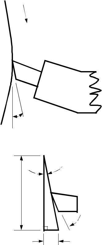
8.3 LATHE TOOLBITS
• A lathe toolbit is shown in the figure below, with a few terms defined.
side cutting edge angle
end cutting
edge angle 

 nose radius
back rake
side rake
side relief
end relief
•In general, as the rake angle increases (positive), the cutting forces are reduced, the surface finish improves, and tool life increases.
•The side edge cutting angle has two effects outlined below,

page 76
1. The angles edge allows a slow build up of cutting forces
Work rotates (the top out of page in this example)
Tool is moved slowly
2. Increase in the side rake angle reduces the chip thickness
T1
T2
T1 < T2 for same area
d
Tool is moved slowly
• The End Relief Angle prevents friction on the flank of the tool. The holder for the bit is often angled, and the end relief angle must be larger than the tool holder angle to prevent rubbing.
page 77
the work rotates this way
tool holder
Effective end relief angle
• The side relief angle has a function similar to the end relief, This angle must exceed the feed helix angle.
helix angle
work circumference = 3.14159 Dia.
effective side relief
feed/rev.
• Increasing the nose radius improves the surface finish. But this reaches a limit.

page 78
8.3.1 Thread Cutting On A Lathe
•Threads are cut using lathes by advancing the cutting tool quickly so that it cuts in a helical band. This helical band is actually a thread. The procedure calls for correct settings of the machine, and also that the helix be restarted at the same location each time.
•The basic procedure is,
1.The tool point must be ground so that it has the same angle as the thread to be cut. Typical angles are 60° for Vee threads, and 29° for ACME threads. A thread gauge can be used to measure thread angles. (also called Centre Gauge or Fish Tail Gauge).
2.The correct gear ratio is required between the machine spindle to the lead screw. This can be determined with the equation,
driver TPILEADSCREW ratio = ---------------- = -------------------------------------
driven TPIWORKPIECE
where,
TPILEADSCREW = the threads per inch on the lead screw (typically 4)
TPIWORKPIECE = the TPI to be cut on the workpiece
For example, to cut 20 TPI we calculate, |
|
||||||
ratio = |
4 |
= 5 |
|
4 |
= |
20 |
The increase is made to match the |
----- |
|
----- |
-------- |
number of teeth available in our |
|||
|
20 |
|
20 |
|
100 |
||
lathe (these figures depend on specific machine tools).
3.The compound slide is set at half the thread angle. This is so that as multiple passes are made to cut the thread (most threads require a few passes to cut), the tool will be advanced in by the compound slide in such a way that only one face cuts. If both faces were used for cutting there would be a good chance of vibrations and chatter. For example, if a 60° thread is being cut, the compound rest is often set at 29°.
4.The cutting tool is set in the holder perpendicular to the work, and the fishtail gauge is used to check the angle of the point.
5.The In-feed is set to the surface of the part for the first pass (quite often the first pass just scratches the surface to allow visual checking of the settings). On each subsequent pass the infeed will be set closer.
6.The cross slide is set at the same location for each cutting pass. i.e., the dial setting is zero.
page 79
7. The In-feed is adjusted on the compound slide for each pass by moving it in a distance. A simple measure of this distance is,
∆ 0.75 = ---------
INFEED TPI
************************** INCLUDE CHASING DIAL FIG 31-13
8. The chasing dial is used to restart the thread cutting in synchronization with what has been cut before. (If this step is not done properly, the notches in a thread might be cut over existing ridges - effectively cutting the entire thread flat to the bottom). The carriage of the lathe in driven across by a split nut. When the split nut is closed over the lead screw, it begins to move. It must be clamped over the lead screw when it is at the right angle. The method for doing this is with the chasing dial. The chasing dial has 16 different locations to engage at. In some cases you can engage the nut at any time, in other cases there are only a few positions to engage at. The basic rules are,
Calculate the following ratio (the previous example is used for illustration), and reduce the denominator to the smallest integer value.
R = |
TPIWORKPIECE |
= |
20 |
|
5 |
||||
TPI-------------------------------------LEADSCREW |
----- |
= -- |
|||||||
|
|
4 |
|
|
1 |
||||
Other examples could be, |
|
|
|
|
|
|
|
||
|
|
|
1 |
|
3 |
1 |
|
|
|
18 |
9 |
19 |
7-- |
15 |
-- |
|
|
13 |
|
2 |
|
4 |
= |
||||||
----- = |
--, -----, ----- |
= -----, ----- |
----- |
||||||
4 |
2 |
4 |
4 |
8 |
4 |
|
|
16 |
|
Then looking at the denominator only, select the positions of the chasing dial that the carriage can be engaged at,
DENOMINATOR |
WHEN TO ENGAGE CARRIAGE |
|
|
1 |
close nut at any position |
2 |
every 1/8 of dial (e.g., at any line) |
4 |
every 1/4 of dial (e.g., at any line with number) |
8 |
every 1/2 of dial (e.g., 1 and 3, or 2 and 4) |
16 |
every revolution at the same place (e.g., 1) |