
- •1. TABLE OF CONTENTS
- •2. BASIC MANUFACTURING
- •2.1 INTRODUCTION
- •2.2 PRACTICE PROBLEMS
- •3. MANUFACTURING COST ESTIMATING
- •3.1 COSTS ESTIMATES
- •3.2 COGS (COST OF GOODS SOLD)
- •3.3 VALUE ENGINEERING
- •3.4 REFERENCES
- •4. BASIC CUTTING TOOLS
- •4.1 CUTTING SPEEDS, FEEDS, TOOLS AND TIMES
- •4.2 HIGH SPEED MACHINING
- •4.3 REFERENCES
- •5. CUTTING THEORY
- •5.1 CHIP FORMATION
- •5.2 THE MECHANISM OF CUTTING
- •5.2.1 Force Calculations
- •5.2.1.1 - Force Calculations
- •5.2.1.2 - Merchant’s Force Circle With Drafting (Optional)
- •5.3 POWER CONSUMED IN CUTTING
- •5.4 PRACTICE QUESTIONS
- •5.5 TEMPERATURES IN CUTTING
- •5.6 TOOL WEAR
- •5.7 CUTTING TOOL MATERIALS
- •5.7.1 A Short List of Tool Materials
- •5.8 TOOL LIFE
- •5.8.1 The Economics of Metal Cutting
- •5.9 REFERENCES
- •5.10 PRACTICE PROBLEMS
- •6. SAWS
- •6.1 SPEEDS AND FEEDS
- •6.2 PRACTICE PROBLEMS
- •7. DRILLING
- •7.1 TYPES OF DRILL PRESSES
- •7.2 TYPICAL DRILL PRESS OPERATIONS
- •7.3 TYPICAL DRILL BITS
- •7.3.1 Reamers
- •7.3.2 Boring
- •7.3.3 Taps
- •7.4 DRILLING PROCESS PARAMETERS
- •7.4.1 The mrr For Drilling
- •7.5 PRACTICE PROBLEMS
- •8. LATHES
- •8.1 INTRODUCTION
- •8.2 OPERATIONS ON A LATHE
- •8.2.1 Machine tools
- •8.2.1.1 - Production Machines
- •8.3 LATHE TOOLBITS
- •8.3.1 Thread Cutting On A Lathe
- •8.3.2 Cutting Tapers
- •8.3.3 Turning Tapers on Lathes
- •8.4 FEEDS AND SPEEDS
- •8.4.1 The mrr for Turning
- •8.4.2 Process Planning for Turning
- •8.5 PRACTICE PROBLEMS
- •9. MILLING
- •9.1 INTRODUCTION
- •9.1.1 Types of Milling Operations
- •9.1.1.1 - Arbor Milling
- •9.1.2 Milling Cutters
- •9.1.3 Milling Cutting Mechanism
- •9.1.3.1 - Up-Cut Milling
- •9.1.3.2 - Down-Cut Milling
- •9.2 FEEDS AND SPEEDS
- •9.2.1 The mrr for Milling
- •9.2.2 Process Planning for Prismatic Parts
- •9.2.3 Indexing
- •9.3 PRACTICE PROBLEMS
- •10. GRINDING
- •10.1 OPERATIONS
- •10.2 MACHINE TYPES
- •10.2.1 Surface
- •10.2.2 Center
- •10.2.3 Centerless
- •10.2.4 Internal
- •10.3 GRINDING WHEELS
- •10.3.1 Operation Parameters
- •10.4 PRACTICE PROBLEMS
- •11. SURFACES
- •11.1 MEASURES OF ROUGHNESS
- •11.2 METHODS OF MEASURING SURFACE ROUGHNESS
- •11.2.1 Observation Methods
- •11.2.2 Stylus Equipment
- •11.2.3 Specifications on Drawings
- •11.3 OTHER SYSTEMS
- •11.4 PRACTICE PROBLEMS
- •11.4.0.1 - Roundness Testing
- •11.4.0.1.1 - Intrinsic Roundness Testing
- •11.4.0.1.2 - Extrinsic Roundness Testing
- •11.4.0.1.3 - Practice Problems
- •11.5 PRACTICE PROBLEMS
- •35. METROLOGY
- •35.1 INTRODUCTION
- •35.1.1 The Role of Metrology
- •35.2 DEFINITIONS
- •35.3 STANDARDS
- •35.3.1 Scales
- •35.3.2 Calipers
- •35.3.3 Transfer Gauges
- •35.4 INSTRUMENTS
- •35.4.1 Vernier Scales
- •35.4.2 Micrometer Scales
- •35.4.2.1 - The Principle of Magnification
- •35.4.2.2 - The Principle of Alignment
- •35.4.3 Dial Indicators
- •35.4.4 The Tool Makers Microscope
- •35.4.5 Metrology Summary
- •35.5 PRACTICE PROBLEMS
- •35.5.0.1 - Interferometry (REWORK)
- •35.5.0.1.1 - Light Waves and Interference
- •35.5.0.1.2 - Optical Flats
- •35.5.0.1.3 - Interpreting Interference Patterns
- •35.5.0.1.4 - Types of Interferometers
- •35.5.0.2 - Laser Measurements of Relative Distance
- •35.5.0.2.1 - Practice Problems
- •35.6 GAUGE BLOCKS
- •35.6.1 Manufacturing Gauge Blocks
- •35.6.2 Compensating for Temperature Variations
- •35.6.2.1 - References
- •35.6.3 Testing For Known Dimensions With Standards
- •35.6.3.1 - References
- •35.6.4 Odd Topics
- •35.6.5 Practice Problems
- •35.6.6 Limit (GO & NO GO) Gauges
- •35.6.6.1 - Basic Concepts
- •35.6.6.2 - GO & NO GO Gauges Using Gauge Blocks
- •35.6.6.3 - Taylor’s Theory for Limit Gauge Design
- •35.6.6.4.1 - Sample Problems
- •35.6.7 Sine Bars
- •35.6.7.1 - Sine Bar Limitations
- •35.6.7.1.1 - Practice Problems
- •35.6.8 Comparators
- •35.6.8.1 - Mechanical Comparators
- •35.6.8.2 - Mechanical and Optical Comparators
- •35.6.8.3 - Optical Comparators
- •35.6.8.4 - Pneumatic Comparators
- •35.6.9 Autocollimators
- •35.6.10 Level Gauges
- •35.6.10.1 - Clinometer
- •35.6.10.2 - The Brookes Level Comparator
- •35.6.11 The Angle Dekkor
- •35.7 MEASURING APARATUS
- •35.7.1 Reference Planes
- •35.7.1.1 - Granite Surface Plates
- •35.7.1.2 - Cast Iron Surface Plates
- •35.7.2 Squares
- •35.7.2.1 - Coordinate Measureing Machines
- •35.7.2.2 - Practice Problems
- •AM:35.7.3 Coordinate Measuring Machines (CMM)
- •36. ASSEMBLY
- •36.1 THE BASICS OF FITS
- •36.1.1 Clearance Fits
- •36.1.2 Transitional Fits
- •36.1.3 Interference Fits
- •36.2 C.S.A. B97-1 1963 LIMITS AND FITS(REWORK)
- •36.3 CSA MODIFIED FITS
- •36.4 CSA LIMITS AND FITS
- •36.5 THE I.S.O. SYSTEM
- •36.6 PRACTICE PROBLEMS
- •42. WELDING/SOLDERING/BRAZING
- •42.1 ADHESIVE BONDING
- •42.2 ARC WELDING
- •42.3 GAS WELDING
- •42.4 SOLDERING AND BRAZING
- •42.5 TITANIUM WELDING
- •42.5.1 Practice Problems
- •42.6 PLASTIC WELDING
- •42.7 EXPLOSIVE WELDING
- •42.7.1 Practice Problems
- •43. AESTHETIC FINISHING
- •43.1 CLEANING AND DEGREASING
- •43.2 PAINTING
- •43.2.1 Powder Coating
- •43.3 COATINGS
- •43.4 MARKING
- •43.4.1 Laser Marking
- •43.5 PRACTICE PROBLEMS
- •44. METALLURGICAL TREATMENTS
- •44.1 HEAT TREATING
- •44.2 ION NITRIDING
- •44.3 PRACTICE PROBLEMS
- •45. CASTING
- •45.1 SAND CASTING
- •45.1.1 Molds
- •45.1.2 Sands
- •45.2 SINGLE USE MOLD TECHNIQUES
- •45.2.1 Shell Mold Casting
- •45.2.2 Lost Foam Casting (Expandable Pattern)
- •45.2.3 Plaster Mold Casting
- •45.2.4 Ceramic Mold Casting
- •45.2.5 Investment Casting
- •45.3 MULTIPLE USE MOLD TECHNIQUES
- •45.3.1 Vacuum Casting
- •45.3.2 Permanent Mold Casting
- •45.3.2.1 - Slush Casting
- •45.3.2.2 - Pressure Casting
- •45.3.2.3 - Die Casting
- •45.3.3 Centrifugal Casting
- •45.3.4 Casting/Forming Combinations
- •45.3.4.1 - Squeeze Casting
- •45.3.4.2 - Semisolid Metal Forming
- •45.3.5 Single Crystal Casting
- •45.4 OTHER TOPICS
- •45.4.1 Furnaces
- •45.4.2 Inspection of Casting
- •45.5 Design of Castings
- •45.6 REFERENECES
- •45.7 PRACTICE PROBLEMS
- •46. MOLDING
- •46.1 REACTION INJECTION MOLDING (RIM)
- •46.1.1 References
- •46.2 INJECTION MOLDING
- •46.2.1 Hydraulic Pumps/Systems
- •46.2.2 Molds
- •46.2.3 Materials
- •46.2.4 Glossary
- •46.3 EXTRUSION
- •46.4 PRACTICE PROBLEMS
- •47. ROLLING AND BENDING
- •47.1 BASIC THEORY
- •47.2 SHEET ROLLING
- •47.3 SHAPE ROLLING
- •47.4 BENDING
- •48. SHEET METAL FABRICATION
- •48.1 SHEET METAL PROPERTIES
- •48.2 SHEARING
- •48.2.1 Progressive and Transfer Dies
- •48.2.2 DRAWING
- •48.3 DEEP DRAWING
- •48.4 SPINNING
- •48.5 MAGNETIC PULSE FORMING
- •48.6 HYDROFORMING
- •48.7 SUPERPLASTIC FORMING
- •48.7.1 Diffusion Bonding
- •48.8 PRACTICE PROBLEMS
- •49. FORGING (to be expanded)
- •49.1 PROCESSES
- •49.1.1 Open-Die
- •49.1.2 Impression/Closed Die
- •49.1.3 Heading
- •49.1.4 Rotary Swaging
- •50. EXTRUSION AND DRAWING
- •50.1 DIE EXTRUSION
- •50.1.1 Hot Extrusion
- •50.1.2 Cold Extrusion
- •50.2 HYDROSTATIC EXTRUSION
- •50.3 DRAWING
- •50.4 EQUIPMENT
- •50.5 PRACTICE PROBLEMS
- •51. ELECTROFORMING
- •51.1 PRACTICE PROBLEMS
- •52. COMPOSITE MANUFACTURING
- •52.1 FIBER REINFORCED PLASTICS (FRP)
- •52.2 COMPOSITE MANUFACTURING
- •52.2.1 Manual Layup
- •52.2.2 Automated Tape Lamination
- •52.2.3 Cutting of Composites
- •52.2.4 Vacuum Bags
- •52.2.5 Autoclaves
- •52.2.6 Filament Winding
- •52.2.7 Pultrusion
- •52.2.8 Resin-Transfer Molding (RTM)
- •52.2.9 GENERAL INFORMATION
- •52.2.10 REFERENCES
- •52.2.11 PRACTICE PROBLEMS
- •53. POWDERED METALLURGY
- •53.1 PRACTICE PROBLEMS
- •54. ABRASIVE JET MACHINING (AJM)
- •54.1 REFERENCES
- •54.2 PRACTICE PROBLEMS
- •55. HIGH PRESSURE JET CUTTING
- •56. ABRASIVE WATERJET CUTTING (AWJ)
- •57. ULTRA SONIC MACHINING (USM)
- •57.1 REFERENCES
- •57.1.1 General Questions
- •58. ELECTRIC DISCHARGE MACHINING (EDM)
- •58.1 WIRE EDM
- •58.2 PRACTICE PROBLEMS
- •58.3 REFERENCES
- •59. ELECTROCHEMICAL MACHINING (ECM)
- •59.1 REFERENCES
- •59.2 PRACTICE PROBLEMS
- •60. ELECTRON BEAM MACHINING
- •60.1 REFERENCES
- •60.2 PRACTICE PROBLEMS
- •61. ION IMPLANTATION
- •61.1 THIN LAYER DEPOSITION
- •61.2 PRACTICE PROBLEMS
- •62. ELECTROSTATIC SPRAYING
- •62.1 ELECTROSTATIC ATOMIZATION METHOD
- •62.2 PRACTICE PROBLEMS
- •63. AIR-PLASMA CUTTING
- •63.1 REFERENCES
- •63.2 PRACTICE PROBLEMS
- •64. LASER CUTTING
- •64.1 LASERS
- •64.1.1 References
- •64.2 LASER CUTTING
- •64.2.1 References
- •64.3 PRACTICE PROBLEMS
- •65. RAPID PROTOTYPING
- •65.1 STL FILE FORMAT
- •65.2 STEREOLITHOGRAPHY
- •65.2.1 Supports
- •65.2.2 Processing
- •65.2.3 References
- •65.3 BONDED POWDERS
- •65.4 SELECTIVE LASER SINTERING (SLS)
- •65.5 SOLID GROUND CURING (SGC)
- •65.6 FUSED DEPOSITION MODELLING (FDM)
- •65.7 LAMINATE OBJECT MODELING (LOM)
- •65.8 DIRECT SHELL PRODUCTION CASTING (DSPC)
- •65.9 BALLISTIC PARTICLE MANUFACTURING (BPM)
- •65.9.1 Sanders Prototype
- •65.9.2 Design Controlled Automated Fabrication (DESCAF)
- •65.10 COMPARISONS
- •65.10.1 References
- •65.11 AKNOWLEDGEMENTS
- •65.12 REFERENCES
- •65.13 PRACTICE PROBLEMS
- •66. PROCESS PLANNING
- •66.1 TECHNOLOGY DRIVEN FEATURES
- •66.2 MOST SIGNIFICANT FEATURE FIRST
- •66.3 DATABASE METHODS
- •66.4 MANUFACTURING VOLUMES
- •66.5 STANDARD PARTS
- •66.6 PRACTICE PROBLEMS
- •66.6.1 Case Study Problems
- •66.6.1.1 - Case 1
- •66.7 REFERENCES
page 157
35.5.0.1 - Interferometry (REWORK)
•Light waves can be used to measure various attribute, such as distance by generating interference patterns.
•In general, if we take a single beam of light, and split it, the two separated beams will have the same frequency, and phase. If the two beams take different length paths, but eventually intersect each other, then they will form interference patterns, much as is found in wave tanks.
35.5.0.1.1 - Light Waves and Interference
•In reality normal light from the sun, or a light bulb, etc. has many frequencies, directions, and phases. But when we use special light sources, such as lasers, the light is monochromatic. Each photon is in phase, and has the same frequency as all the others. In effect we have a ‘superphoton’.
•Aside: as a simple review, recall that light is just an electromagnetic field the is becoming more and less intense at a very high frequency. If you could shake a simple magnet fast enough (this is impossible physically) you could make light, radiowave, X-rays, heat that you can feel, etc.
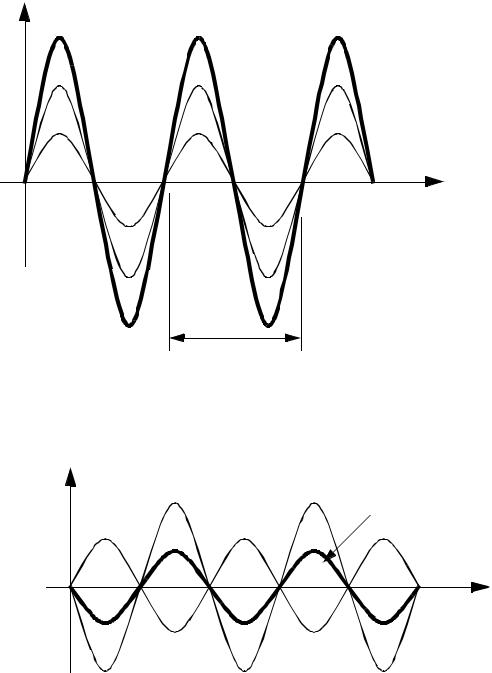
•another principle of importance to our discussion is superposition, and interference.If we have two or more photons in phase, their individual intensities will add together to a new higher intensity.

page 158
amplitude |
A+B = result |
wave B |
wave A |
time or |
linear position |
wavelength (lambda)
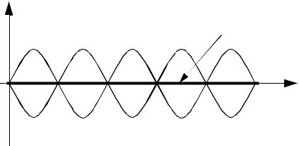
• The superposition approach where waves are added, also has the effect of reducing wave heights when waves are out of phase. At the most extreme, when the waves are 180° out of phase, the resultant wave is the difference in height.
amplitude |
wave B |
A + B = result |
wave A |
• If the two out of phase waves are the same magnitude, then they will cancel out (interfere) completely,

page 159
amplitude |
|
|
A + B = result |
wave A |
wave B |
35.5.0.1.2 - Optical Flats
•Optical Flats use a transparent surface with high precision finishes.
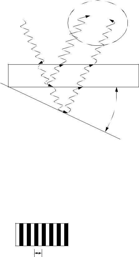
•a monochromatic light is shone through the optical flat, at the bottom interface, some of the light is reflected back, while some light escapes to reflect off the surface, and back through the flat. It is when some of the light is reflected at the back side of the optical flat that the beam is split. The distance between the flat and the surface then changes the pathlength of the two beams. As they are reflected back, the light waves interfere, and create light/dark fringes that are a function of distance between the flat and the plat.

page 160
When viewed, these two
Light source |
waves may or may not be out |
|
(monochromatic) |
||
of phase depending upon the |
||
|
||
|
length of the path. |
Optical Flat
a |
c |
Work
Surface
b |
θ |
•There are some mathematical relationships that should be observed,
1.θ should be small. Large values will introduce problems, and decrease accuracy.
2.the distance ‘abc’ will determine if a light/dark stripe is seen.
|
1 |
ab + bc = λ n |
ab + bc = λ |
n + -- |
|
|
2 |
|
Dark |
|
Light |
3. The distance between two fringes will represent a change in height of λ /2
height changes by λ /2